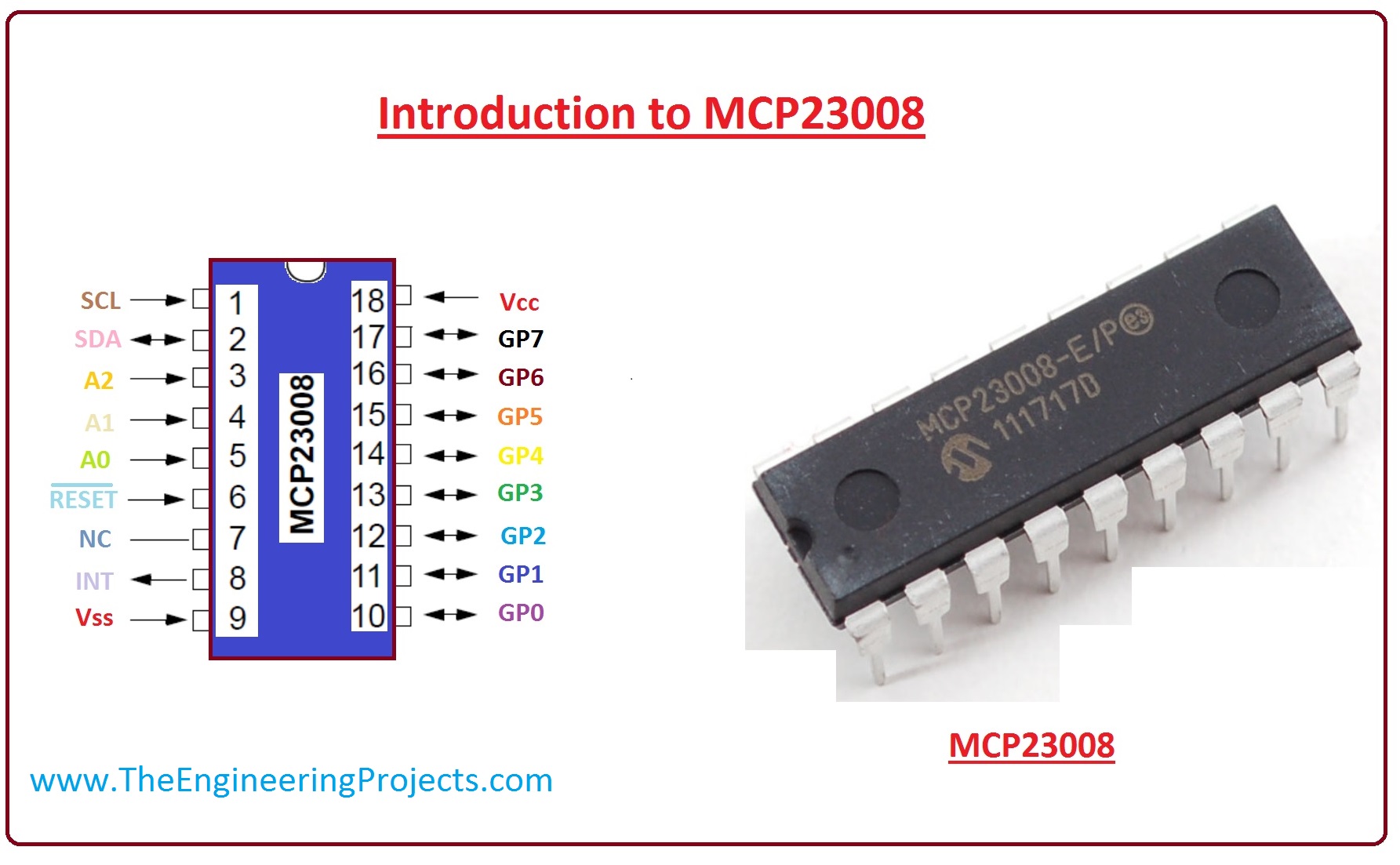
Introduction to MCP23008
- MCP23008 provides an 8-bit parallel input/output expansion for I2C bus and SPI applications. This microcontroller has 8-bit configuration registers for input, output and polarity changing.
- In this microcontroller, four pins are configured for inputs and four for outputs. These pins are designed in such a way when the input level is changed, the associated output pin is driven to the same level. This phenomenon is happened by the MCU reading the inputs pins and writing the appropriate value to the output pins.
- This module is available in small space saving 20-lead SSOP packages. Adding small 6-lead PIC10F202 in a SOT-23 package makes it available for small overall PCB areas.
- Either it can connect with a power supply of 5V using the Vdd and GND test pins, or can connect with a 9V power supply or power adapter into the plug.

- Now, discuss its pinouts, with detailed parameters.
MCP23008 Pinout & Description
There is the main 18 pinout of MCP23008, which are described below with a detailed description.| Pin# | Type | Parameters |
| Pin#1 | SCL/SCK | It is a Serial clock input. |
| Pin#2 | SDA/SI | It is a Serial data I/O (MCP23008)/Serial data input (MCP23S08) pin. |
| Pin#3 | A2/SO | It is a hardware address input (MCP23008)/Serial data output (MCP23S08). It (A2) must be biased externally. |
| Pin#4 | A1 | It is a Hardware address input. It Must be biased externally. |
| Pin#5 | A0 | It is a Hardware address input. It Must be biased externally. |
| Pin#6 | RESET | This is an external reset input. |
| Pin#7 | NC/CS | No connect (MCP23008)/External chip select input (MCP23S08). |
| Pin#8 | INT | It is an Interrupt output. It Can be configured for active-high, active-low or open-drain. |
| Pin#9 | VSS | It is used for Ground. |
| Pin#10 | GP0 | It is a Bidirectional I/O pin. It can be enabled for interrupt-on-change and/or internal weak pull-up resistor. |
| Pin#11 | GP1 | It is a Bidirectional I/O pin. It can be enabled for interrupt-on-change and/or internal weak pull-up resistor. |
| Pin#12 | GP2 | It is a Bidirectional I/O pin. It can be enabled for interrupt-on-change and/or internal weak pull-up resistor. |
| Pin#13 | GP3 | It is a Bidirectional I/O pin. It can be enabled for interrupt-on-change and/or internal weak pull-up resistor. |
| Pin#14 | GP4 | It is a Bidirectional I/O pin. It can be enabled for interrupt-on-change and/or internal weak pull-up resistor. |
| Pin#15 | GP5 | It is a Bidirectional I/O pin. It can be enabled for interrupt-on-change and/or internal weak pull-up resistor. |
| Pin#16 | GP6 | It is a Bidirectional I/O pin. It can be enabled for interrupt-on-change and/or internal weak pull-up resistor. |
| Pin#17 | GP7 | It is a Bidirectional I/O pin. It can be enabled for interrupt-on-change and/or internal weak pull-up resistor. |
| Pin#18 | VDD | Power pin. |
| Pin#19 | N/C | N/C |
Features of MCP23008 Features
- These are the main features of MCP23008.
- This module consists of Two 8-bit GPIO expanders.
- It is available in both I2C and SPI interfacing.
- This board has four switches and four LEDs to demonstrate the input/output functionality.
- It has headers for the serial interface and GPIO port to allow evaluation in a user-defined application.
- It has polarity inversion register to configure the input port data.
- It also has an external reset input.
- Its operating voltage is 1.8 to 5.5V at -40 Celsius to +85 Celsius.
MCP23008 Arduino Interfacing
- The project which we are going to discuss will tell us how we can interface an MCP23008 I/O port expander to an Arduino microcontroller.
-
First, we discuss the component of projects.
- Component of Project
- These are the main components of the project.
- MCP23008 I/O Port Expander.
- A few 220O resistors.
- A few LEDs.
- Arduino microcontroller.
- Let's now we explain our projects with detail.
- In this circuit with each input and output pin, we connect a 220O resistor and an LED.
-
For input supply, we have connected +5V to Vdd and Vss to GND.
-
Now, connect pin no 1 of the MCP23008, which is SCL to analog pin no 5 of Arduino. This provides clock synchrony between Arduino and the I/O port expander chip.
-
After this, we have connected pin no 2 of MCP23008, which is SDA to analog pin no 4 of Arduino. This connection allows data transfer between the Arduino and the I/O port expander chip.
-
In this project there is no use of interrupts pin, so leave INT pin unconnected.
-
We are not using the RESET pin, we connect it to +5V. If you want to use it, you just connect it with digital pin no the Arduino. If you want to reset all outputs than you draw this pin low in cade.
-
After that, we will connect address pin A0, A1, and A2, to ground. It makes the address of these 3 pins 000.
- For better understanding Lets see the picture.

Applications of MCP23008
- As, we know this microcontroller works on both I2C and SPI protocol, due to this feature it is used in some projects and devices which use both protocols.
So, friends, that was all about MCP23008, if you have any question about it please ask in comments, I will solve your problems. Thanks for reading. Take care until the next tutorial.


