When the time comes to commence house renovations, one of the first things you might ask yourself is whether you should undertake some of the tasks on your own. While you might save money on some jobs, it can sometimes be at the detriment of a high-quality finish. This holds true when it comes to interior and exterior painting and decorating. When your property is in need of a fresh lick of paint, here are just a few of the many reasons why calling in the experts can be the best option for you.
They Boast Years of Experience
When you entrust painting and decorating experts like Dublin Painters with the task of refreshing your home’s interior and exterior, you can rest assured that they have the necessary experience to do the job to a high standard ...
Almost everyone has experienced losing data that is very important to them. Have you experienced this too? Some people have lost personal data. For example, there may be some videos and images of a special event that can never be retrieved again.
People who have started their businesses may have created data that will help them improve their business. Then, they can lose it just like that. Without backup data, they need to start from scratch. This will take a lot of time, money, and effort to do.
You have important data, and you need to make an effort to ensure that you will get to keep them. You can look into people who can do business process outsourcing to help you gather and keep your data safe. You need your data to help your business grow an ...
Irrespective of the size and nature of your business, managing human resources is a herculean task. Enforcing your company policies and handling grievances while keeping the workforce motivated and engaged demands a lot of communication and cooperation. In addition to this, your human resources department also needs to identify the skill gaps that exist in the workforce and hire the right candidates to fill them. Thus, HR managers can be considered as both the heart and brain of your organisation. They ensure a smooth workflow by keeping a check on company standards and needs.
However, in the last few years, the role of an HR manager has extended beyond the traditional hiring and firing activities. It has now become more focused on areas like empl ...
Hello friends, I hope this article finds you happy, healthy, and content. Today, we are about to discuss one of the most commonly known types of transistors which you might have heard of many times when reading about transistors, the transistor under study is none other than the “Bipolar Junction Transistor’’, also known as BJT . In this article, we will go through the basics of the bipolar junction transistor including its meaning ,definition, types, characteristics, and applications. So, let's get started.
Definition of BJT
A BJT in its full form is written as bipolar junction transistor and we can define it as,
"A bipolar junction transistor is a three-terminal semiconductor device which is made up of two PN junctions within its structure a ...
Cloud storage providers are important for companies to keep their files organized, share files with others, and back up their information in case of an attack or disaster. But there are many ways to approach this decision incorrectly or inefficiently, especially considering the hundreds of providers you have to choose from.
What are the most common mistakes companies make when choosing a cloud storage provider, and how can you avoid them?
The Importance of Cloud Storage
The importance of cloud storage software is hard to overstate. Your decision will have an effect on:
File storage. How can you be sure that your files are stored fully and reliably? With an unreliable or untested provider, you’ll never feel 100 percent confident that your mate ...
In the previous tutorial, we have discussed the basics of ESP8266 modules and have also had a look at the different WiFi modules based on ESP8266. In today's tutorial, we are going to set up Arduino Environment for NodeMCU Programming. Today we will prepare the development environment and build code to blink an LED and report status on the Serial Port (to validate the configuration). We will use the Arduino IDE for coding and the NodeMCU board (a module that works with an ESP8266). Simple integration. Zero hardware complexity.
The ESP8266 is an extremely robust and versatile microcontroller, which has proven to be a powerful tool in building Internet of Things solutions. What makes the ESP8266 such a popular tool is the perfect integration between ...
The Internet of Things (IoT) and the Industry 4.0. Distinct technological revolutions but with a common goal: To integrate equipment (digital or analog) to a computer network.
And to be part of this revolution, the developer goes out of its way to include wired ethernet modules or WIFI modules in its circuits. Which increases complexity, circuit size and development cost.
What if I told you that already has a built-in WIFI microcontroller? And that it fits in the palm of your hand? For just 1 US dollar?
Today I’m going to introduce you to the ESP8266 microcontroller, from Espressif. And for those of you who already program in 8Bit microcontrollers like the Atmega328 (one of the most common on Arduino) and struggle to build your code in the modic SR ...
Parts Pre-order Service provides customers order components and saves them for their JLCPCB SMT service. Consumers prepay for the parts and buy the required components in advance to ensure sufficient components are ready anytime. Meanwhile, they can immediately arrange the supply of parts through the advance sale for their electronic products. The parts save in their own library, safe and easy.
Pre-order service accumulates different demands from people all around the world, is making parts need more clear and easier, therefore JLCPCB cooperates with customers to help complete orders, the order in large quantities, help win more discounts, and create maximum value and benefits for customers.
JLCPCB Parts Pre-order build up supply amid a global s ...
Mathematics and its branches make a group of disciplines that appear the most challenging for students. While you could have an innate talent for sciences and good memory, this can’t be the only thing to rely on in learning maths.
It also requires consistency and tireless work. What makes math studies even more difficult is that students often have to master many disciplines at the same time – algebra, geometry, mathematical analysis, statistics, etc. Not counting other vital college subjects.
With such great pressure, it seems impossible to succeed in every single subject. In fact, it would be impossible but for the technologies, we have nowadays. Thanks to the wide popularity of academic help services and their availability, students can receive ...
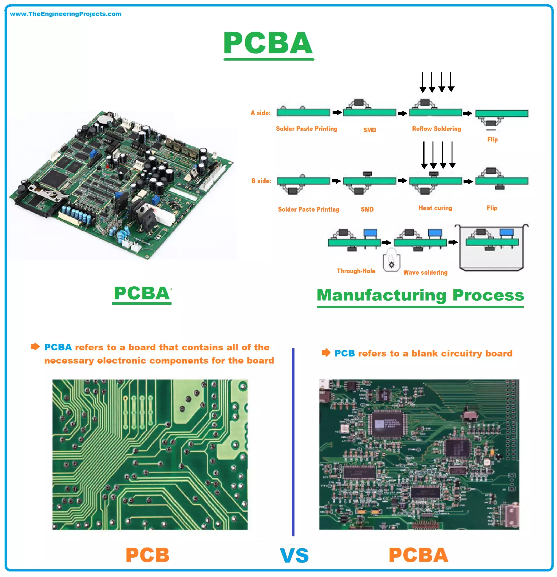
Hey Guys! Hope you’re well. I welcome you on board. In this post today, I’ll walk you through PCBA (Printed Circuit Board Assembly) in detail. It's our 4th tutorial in the PCB learning series.
In the 1st tutorial, we studied printed circuit board(PCB) in detail and learned that PCB provides physical support and electrical connection through conductive copper layers for the electronic components placed on the board. We have seen in our previous tutorials that when we place our PCB order on some PCB fabrication house, they provide us with a PCB board without electronic components. We have to solder the electronic components on the board. But now these PCB companies also offer a service to provide finished PCB boards with electronic components attach ...