Simulate First Electronics Project in Proteus ISIS
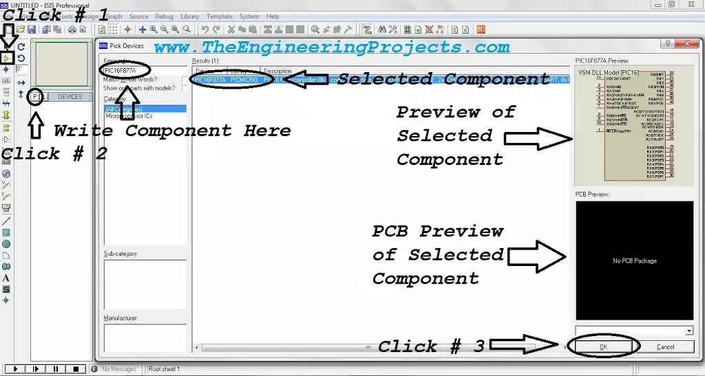
Hello friends, I hope you all are doing great. In today's tutorial, we will simulate our
First Electronics Project in Proteus ISIS. It's our 2nd tutorial in Proteus series. In our previous tutorial, we have seen a basic Introduction to Proteus and today, we will design a simple electronics circuit in it and will also simulate it.
If you want to work on Proteus, then you must have some prior knowledge about electronics. Proteus doesn't provide any suggestion about circuit designing so if you don't have electronics knowledge then you can't work with Proteus. Throughout this series, I will keep on explaining electronics circuits as well and will also embedded related components' links. So, if you are new to electronics then no need to worry and just follow these instructions and also do read those embedded links to understand electronic components. So, let's Create our First Project in Proteus:
Simulate First Electronics Project in Proteus ISIS
- Open your Proteus ISIS software and then click on Components Mode in left menu tab, as shown in the figure.
- After that click on the P (Pick from Libraries) Button, and a new window will open up.
- This new window is called Pick Devices and is used to make search for electronics components.
- Proteus has a huge database of electronics components in the form of libraries. i.e. Diode Library will have all the diode components.
- So, from these millions of components, we need to make a search for our required components to design electronic circuit.
- You can see Pick Devices window in below figure, so let's first discuss its layout:
- Keywords textbox is used to make a search for any component and Proteus will display the related components in Results panel. ( We will search in a while )
- Category Section displays all the categories available in Proteus and when you click on any category then it's components will be displayed in Results panel.
- After that, we have Sub-category & Manufacturer, rite now I don't have any.
- On the right side we have Schematic Preview & PCB Review, so when we select any component then its respective Previews will be shown here.
- So, now let's make a search for LED, as shown in below figure:
- As you can see in above figure that Proteus has provided us with 141 Results and I have boxed four LEDs, which I am going to use in my circuit.
- Moreover, Category section is now showing only those categories which are related to searched keyword.
- Moreover, we also have a Schematic Preview but we don't have any PCB Preview as it's not available for this component.
- So, double click on these four LEDs and they will be added in Proteus workspace.
- Moreover, we also need to add resistance so make a search for resistance, as shown in below figure:
- Double click on this RES component and then close this Pick Devices window.
- You will get these selected components in the Devices section, as shown in below figure:
- As we are designing a simple project so we have selected just four components but in complex projects, we have a long list of components in this Devices section and it proves quite helpful.
- So, let's place these components, one by one in the central work area.
- You can drag & drop them OR can select by clicking and then again click to place.
- I have placed these components in the work area, as shown in figure on right side.
- So, now let's connect them together using wires and for that, we need to click on the pin terminal of each component.
- I have combined these electronic components together using wires, as shown in below figure:
- Now we need to provide voltage supply to this circuit and there are several voltage sources in Proteus. ( We will cover them in coming lectures )
- For now, let's click on the Terminals Mode in the left Toolbar and you will get Proteus Terminals, as shown in figure on right side.
- From these terminals, we are going to use Power & Ground, so place them in the circuit, as shown in below figure:
- We will discuss all these Terminal Components in detail in our coming lectures.
- If we place multiple Ground components in the circuit then Proteus will consider them all as connected/short.
- These Terminals are quite helpful, as in complex circuits, these wires can become too messy and we can avoid them by using these terminals.
- So, we have completely designed our circuit but we need to change the properties of these components a little.
- So, double click on resistance to open its Properties Panel, as shown in below figure:
- From this Edit Component window, we can edit different properties of selected component.
- As you can see, first we have Component Reference, that's the name of our component i.e. R1. If we have multiple resistances, then there names will be R2, R3 and so on.
- We can't have multiple items with same Component Reference, as it will create an error.
- Second Property defines the resistance of the component and I have changed it from 10k to 1k.
- Then we have Model Type and its analog.
- Finally we have PCB Package, we will use it when we will be designing the PCB design of this circuit.
- So, click on the OK Button and resistance value will change from 10k to 1k.
- Now, double click on first LED to open its Properties Panel, as shown in below figure:
- As LED is a bit complex component as compared to resistance, that's why it has a lot more Properties to Edit.
- As we are designing a digital circuit, so we need to change the Model Type of LED from Analog to Digital and then click on the OK Button.
- You need to change this Model Type for all these four LEDs.
- So, now we have completely designed our first electronic circuit in Proteus.
- Let's run this simulation, by clicking the Play button at the bottom.
- If everything goes fine, then all LEDs will glow, as shown in below figure:
- We have successfully simulated our first electronics circuit in Proteus ISIS and you can see these LEDs have different colors as specified in their Reference Value.
So, that was all for today. I hope you have enjoyed today's tutorial. In the next lecture, we will have a look at How to use Relays in Proteus ISIS. Till then take care & have fun !!! :)
Introduction to Proteus
Hello readers, I hope you all are doing great. In today's tutorial, I am going to share a detailed
Introduction to Proteus. It's our first tutorial in Proteus series. Today's tutorial is for beginners but still I would suggest you to read it once, as I am going to explain why Proteus?
Throughout our Engineering Course, we have to design a lot of electronics or embedded circuits and it's always a best approach to simulate these circuits first on some simulation software i.e. Proteus, PSPice etc., before assembling them on actual hardware. Among these simulation software, Proteus is my favorite one so let's get started with detailed Introduction to Proteus:
Introduction to Proteus ISIS
- Proteus Design Suite (designed by Labcenter Electronics Ltd.) is a software tool set, mainly used for creating schematics, simulating Electronics & Embedded Circuits and designing PCB Layouts.
- Proteus ISIS is used by Engineering students & professionals to create schematics & simulations of different electronic circuits.
- Proteus ARES is used for designing PCB Layouts of electronic circuits.
- It's available in four languages i.e. English, Chinese, Spanish & French.
Why use Proteus ?
"Our circuit is working perfectly on Proteus but when we have implemented it on hardware, it's not working.
" I receive a lot of such questions from engineering students, that's why, I am explaining what's the real purpose of Proteus:
- Proteus is quite lenient in circuit designing and it works on ideal conditions i.e. if you don't add pull up resistors in Proteus simulation, then it won't give garbage value.
- Proteus is also used for PCB designing, we use Proteus ARES for that. ( We will discuss it in upcoming lectures )
So, when I am working on some electronics circuit, then I first design the
simulation on Proteus ISIS and once I got sure that everything's working fine then I design its circuit on either the vero board or the bread board and again I perform some real world testing & when I got sure that my circuit is fully working then I design its PCB in Proteus ARES.
- Proteus is also used for designing/testing programming codes for different Microcontrollers i.e. Arduino, PIC Microcontroller, 8051 etc.
In Embedded projects, we need to design a programming code for Microcontrollers and for designing such codes you have to perform a lot of testing, which involves uploading code to Microcontroller. So, in such projects, Proteus is a great relief. Let's say, you have to print some strings on 20x4 LCD, then its quite annoying to burn the Microcontroller several times for typographical errors. Instead, design a circuit in Proteus and test your code in the simulation and once you are sure that you are getting perfect output then burn your PIC Microcontroller and test it on real hardware. Quite easy and handy. In the coming classes, I will show you how to burn code in Microcontrollers in Proteus.
Note: In code testing, there's again a possibility that you get different results in real hardware but its quite rare and mostly happens in delay functions.
Getting Started With Proteus
You can download Proteus software from it's
official website and you should also read
How to Download & Install Proteus software. So now I hope you have installed Proteus and ready to work on it:
- Click on Proteus ISIS and it will open up as shown in below image.
- In the central area surrounded by blue lines, we design our circuit i.e. place the components and then join them together.
- As you can see in above figure that we have a lot of icons in Proteus software, so let's first understand these sections one by one.
- In the below image, I have divided the Proteus font-end in four sections:
- Section 1 is a toolbar which you would have seen on many simulation software, it has simple functionalities i.e. first icon to create a new layout, second one to open an existing layout, next one is to save layout, then there comes few zooming options and few other tools which we will discuss in coming tutorials.
- Section 2 has two buttons. P is used to open the components list and E is used for editing purposes, like you want to edit the properties of any component then simply click on that component and then click on E and it will open the properties of that component and you can easily edit it.
- Section 3 has different tools, used for designing circuits, we will discuss them in detail, at the end of today's tutorial.
- Section 4 is the remote control section of Proteus, as it contains four buttons i.e. Play, Step, Pause & Stop. In order to run the simulation, we have to click on this play button.
Component Selection in Proteus ISIS
- As shown in below image, click on the icon that says Click # 1, it's a Component Mode Icon.
- After that click on P button and a new window will open up named Pick Devices.
- In this new window there's a textbox on which Keyword is written, this text box is used for the component search.
- Proteus database has unlimited components in it so now in order to get your desired component, you have to search for it as I did.
- I have searched for PIC16F877A and Proteus provided me that component along with its preview in top right corner and PCB package ( if available ). Unfortunately, my Proteus doesn't have the PCB preview of PIC16F877A that's why it's blank.
- In order to add the component in Proteus workspace, either double click on it or click on the OK button.
Instruments in Proteus ISIS
- There are few measuring instruments available in Proteus, which you can open by clicking the Instruments Icon, as shown in figure on right side.
- First one is oscilloscope, we use it for viewing the behavior of different signals generated.
- Another important instrument is Virtual Terminal, it is shown on the fourth number. This Virtual Terminal is used for checking data coming through Serial Port.
- Then there's Signal Generator, it is used to generate signal like sine wave of desired frequency.
- We also have Voltmeter & Ammeter for both AC & DC.
- We will discuss them in detail in our coming lectures.
- As you can see in figure on right side, Icon A is called Graph mode, used to create graphs of voltage and current. It has different style of graphs.
- Icon B and C are voltage and current probes respectively. Suppose you have designed some circuit in Proteus and you want to check the value of voltage at any point in the circuit. In order to do so, simply select this voltage probe and place it there and when you run your circuit, the probe will show the value of voltage above it and same for current probe.
- Icon D is used when we want to design our own component in Proteus.
- Icon E is a simple text editor, used for placing labels, warning or components names etc.
So, that was all for today. I hope you have enjoyed this detailed Introduction to Proteus. If you have any question, feel free to ask in comments and also subscribe through email to our mailing list, so that you don't miss any part of this tutorial series. Stay blessed. Take care.
How to Install and Download Proteus Software
Hello everyone, I hope you all are fine and having fun. Today, I am not going to share a project. Instead, I am gonna share a tutorial in which I will teach you How to download Proteus and install it. It's going to be a quick tutorial because there's not much in it to say. You know Proteus is a Paid software and you must pay the company because they have put really great effort into designing this software. So, if you can afford then you must buy the latest version of Proteus software from their Official Website.
In today's post, I am going to share the Full version of Proteus software and it is Proteus 7 Professional, I am sharing it for engineering students. I hope you are going to enjoy this software its not only free but also complete and the Professional version. So, let's get started with How to Install and Download Proteus Software. Please watch this youTube video for better guidance:
How to Install and Download Proteus Software ???
- First of all, download the Proteus 7 Professional software by clicking the below button:
Proteus 7 Professional Free download
Proteus 8.5 Professional Free download
- Once you downloaded the files, now unrar them and place them in some folder.
- The next thing you need to do is to run the Setup file from the package and it will start to install.
- Use the recommended settings and once it's done then it will ask about the key.
- The default key is given in the package so browse it and upload it to the software.
- Once the key is uploaded, now complete the setup and you will get yourself a Proteus software.
- After the completion, one more thing you need to do is to install the software given in the next folder.
- In the path selection, gave it the path to your Proteus software, which you just installed.
- Now hit run and after it's complete, your Proteus will become registered.
- I have made a small video that will explain the above procedure of How to Install and Download Proteus software in a better way.
So, that's all for today, I hope you guys are gonna enjoy this Proteus software free download and gonna write about it in the comments. That's all for today, will meet you guys in the next tutorial. Till then take care !!! :)
Design a Buzzer in Proteus ISIS
Hello friends, hope you all are having fun and enjoying life. Today's post is quite a simple one and is about designing of circuit diagram of buzzer in Proteus ISIS. Buzzer is quite a common electrical component which is used in almost every Embedded Systems project. For example, you have seen a simple UPS, it gives a beep each time the light goes off or it has depleted its battery. Buzzer is normally used for given some indication and normally this indication is kind of a warning.
Proteus has a builtin component for buzzer and its an animated component means it gives a sound (beep) when its turned ON. So, I am gonna use that one and will give you an actual beep on it. So, it won't be much difficult and quite a simple procedure. In this post, I am not gonna interface it with any Microcontroller i.e. Arduino or PIC Microcontroller but if you want then you can quite easily control it using any of them. You simply need to give pulse to it and you can control it. If I get time then I will post the control of buzzer with Arduino. So, let's start with it.
Design a Buzzer in Proteus ISIS
- First of all, get components from the Proteus library as shown in below figure:
- Now after selecting these components, design a circuit diagram in Proteus as shown in below figure:
- In the above circuit, I have used an optocoupler PC817 in order to control the buzzer.
- The optocoupler is controlled by a simple logic operator, now when you change the logic operator from 1 to 0 the buzzer will turn on.
Note:
- Optocoupler is working here on inverse logic i.e. when we send 1 then its OFF and when we send 0 then its ON.
- If you are designing it on hardware then you can use PC817 Optocoupler.
- So now if everything's fine then simply run the simulation and then click on the logic operator and you will get the below results:
- You can see in the above figure, there are two states.
- In the Buzzer ON state LED is OFF but the buzzer will be ON and you will hear a beep like sound, which obviously can't be heard here in the image. :)
- While in the OFF state LED is ON but the buzzer will be OFF and you wont hear anything.
That's quite a simple tutorial and quite easy to understand but still if you have any problem, then ask in comments. Till next tutorial, take care and have fun.
How to use Capacitive Touch Sensor in Proteus ISIS ?
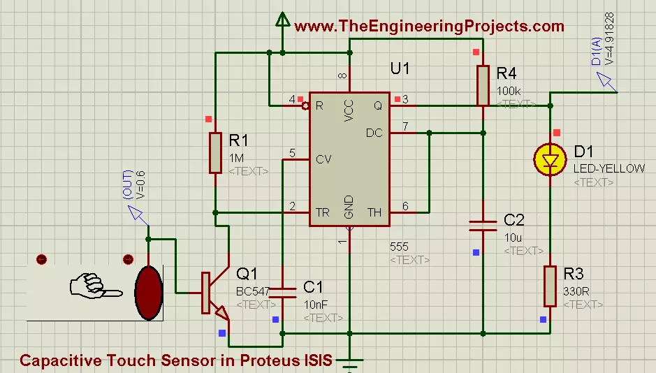
Hello friends, I hope you all are fine and enjoying. Today i am going to share my new project's tutorial which is How to use Capacitive Touch Sensor in Proteus ISIS. It is a very interesting project, and we will be using a 555 Timer while designing this project. If you recall our previous project tutorial which was Angle Control of Servo Motor using 555 Timer in Proteus ISIS, in which 555 timer was generating PWM and was controlling the rotating angle of servo motor.
Now in this project, we have a little different context and now we will be using a 555 Timer in collaboration with Capacitive Touch Sensor. First of all, lets have a little introduction of Capacitive Touch Sensor. Well, if we talk broadly then, in Electrical Engineering Capacitive Touch Sensing is a Technology used in Capacitive Coupling. Capacitive Coupling is a technology which takes Human Body's Capacitance as an input and it measures anything which has a potential difference or which is conductive or any static object which has a dielectric difference from that of air. While designing this technology, one side of the insulator is coated with the conductive material and a very small voltage is applied to this conductive layer. Now after applying the voltages to the conductive layer, a uniform electrostatic field is formed. After that if any conductor (suppose human finger) will come within the vicinity of this field or it touches the other non coated layer of the insulating material then a capacitor will be dynamically formed and if potential difference between both bodies is HIGH then the current will start to flow. That was a little introduction of Capacitive Touch Sensor, and now lets be practical and move towards the Hardware of the Above described tutorial.
You can download the complete simulation of above described project by simply clicking on the button given below:
Download Simulation Files
How to use Capacitive Touch Sensor in Proteus
- In this project, we are using 555 Timer in collaboration with Capacitive Touch Sensor. A 555 timer is an 8 pin IC. Pin # 6 is called threshold pin and for 555 timer threshold level is 5 volts.
- So, 555 timer will trigger above 5 volts and it will generate output which can be collected from pin # 3 represented as ‘Q’ which is output pin of 555 timer.
- While moving toward the simulation of project, first of all place all the components in the proteus workspace, as shown in the image given below:
- First of all we have place Capacitive Touch Sensor and after that we have placed a NPN transistor, then 555 Timer will come and at the output of 555 Timer we have added a LED. The complete circuit diagram ready for simulation is shown in the image given below:
- As long as the finger is out of the vicinity of the electrostatic field, no potential difference occurs and the LED remains in the OFF state.
- Now if we move the finger towards Capacitive Touch Sensor, then and when the potential difference reaches up to 0.6 volts, then 555 triggers and it generates output voltages across LED which are 5 volts but in some cases voltages are lost due to series connected resistances. This phenomenon is shown in below image:
- Now if we further move the finger and take it completely near the sensor, then at this point max potential difference will occur between both point (finger and conductive layer). An important thing to note here is that, we have change the location of our interrupt ( finger) but, same voltages are appearing across LED which are 4.91 volts in this case. It can also seen in the figure given below:
- Now, if we summarize the whole project, then we have seen that the movement of finger is in fact controlling our output. When the finger was out of vicinity of the sensor, then LED was OFF. When we moved the finger in forward direction and came in the vicinity of Electrostatic field, then Sensor gives signal to 555 Timer and Timer makes LED to glow.
- Here's a video demonstrating Capacitive Touch Sensor in Proteus ISIS.
Applications Of Capacitive Touch Sensor
Capacitive sensing touchscreens are now a days commonly used in Digital Audio Players, Mobile Phones and Tablet Computers. Capacitive touch sensors also have the ability to replace Mechanical Buttons. Back in 1928 Russians invented a music instrument known as "Theremin" , in which The Instrument Player was able to control the volume and pitch of the sound without physically touching the instrument. Capacitive Touch Sensors are of basic level but they are back bone of large industrial projects and are widely used in designing some other sensors like:
- Position sensor.
- Humidity sensor.
- Fluid or Water level sensor.
- Proximity sensor etc..
Alright friends, that’s all for today, I hope I have conveyed some knowledge and helped you people in some way. If you have some queries, then ask in comments. Subscribe us via email to get these tutorials straight in your inbox. Till next tutorial, take care and be safe !!! :)
Design a 5V Power Supply in Proteus
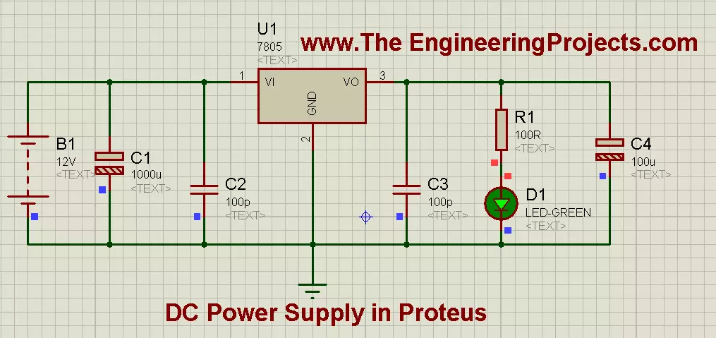
Hello friends, hope you all are fine and enjoying in your life. In the previous post, we have seen How to use Oscilloscope in Proteus ISIS, today I am going share a new and a very important Tutorial which is How to Design a 5V Power Supply in Proteus? This project is very simple and of basic level but importance of this project is that it is used as a base in almost all large electronics project, designed now-a-days. When I start working on any project then the first thing, I need to design is this DC power supply, because without powering up the components, we can't use them. :)
While designing a 5V Power Supply in Proteus ISIS, we will be using Voltage Regulator IC, which is commonly known as 7805. This voltage regulator is used to regulate or change the voltage level of supply voltage. As we all know, most of the batteries available in market are of 12 volts. For example, if you have UPS at your homes then check its battery, it will be of 12V. Similarly, the battery of car or motorcycle is also of 12V. So, 12V has become the standard of electrical batteries. Now, we have known that all batteries are of 12V but the problem comes when we are dealing with sensitive electronic components because they are all designed to operate on 5 volts. Now, as I described earlier that, voltage source available is 12 volts and the operating equipment needs 5 volts to operate. So, we need an intermediate source or such type of DC Power Supply, which can convert the source voltage (12 volts) to operating voltage (5 volts). This problem is eliminated by using 7805 IC, and that’s why it is called Voltage Regulating IC.
So dear Friends, today we will design a 5V power supply, which will be able to change Voltage Level and will provide us our desired voltage. But as I always say, that practice makes a man perfect. Try to design it yourself so that, you also get to know the real application of Voltage Regulator IC. So, let's get started with designing of 5V power supply in Proteus ISIS.
How to Design a 5V Power Supply in Proteus
- You can download the complete simulation of 5V Power Supply in Proteus by clicking the below button:
Design a 5V Power Supply in Proteus
- Voltage Regulating IC 7805 has 3 pins.
- Pin # 1 is used as input pin and it is connected to supply voltages. It is marked as (VI). DC +12 volts are applied to this pin.
- Pin # 2 is called common or ground pin. It is marked as (GND). The whole circuit's common is applied to this pin.
- Pin # 3 is the output pin of 7805. If 12 volts are applied to its input than it automatically generates 5 volts on this pin. This pin is marked as (VO).
- Now, moving towards the designing of the hardware, first of all place all the components in Proteus workspace, as shown in image below:
- In Hardware implementation, first off all apply source voltage (12 volts) to the input pin of 7805 IC. 2 capacitors are also connected in parallel with the source voltage and their ratings are 1000 uf and 100pf respectively.
- On the other side of IC, we also connect 2 capacitors parallel to the gained output voltage (5 volts), and their ratings are 100pf and 100uf respectively. And a LED is also connected in parallel on the load side.
- If you have placed all the components in their perfect place and all the connections are OK, then the resultant proteus simulation will look like as shown in the below image:
- Now if you closely observe the above image then you will notice that Capacitors connected across the 12 volts are of HIGH rating while the Capacitors connected across LED are of LOW rating. The purpose of applying capacitors is to remove noise from our DC voltages. As, we all know that DC voltage source available in market is not that much pure. So, to get pure DC wave Capacitors are connected across it.
- Now when you will run the final simulation then it will look like, as shown in the image given below:
- As you can see that when i ran the simulation, the LED started to glow. Now here is an important thing to note that i have applied a resistance in series with LED. The value of resistance is very low, and very low voltages appear across this resistor. This resistor limits the current and if we directly connect the LED then, their will be chances that the LED may burn out.
- We can justify it as: From ohms law : V=IR, and by rearranging it, we get : I=V/R .
- Now if we remove resistor then R=0, which means: I=V/0 and it lead us to conclude that: I= infinity or maximum in this case. So the only purpose of the resistor is to limit current.
Alright friends, that’s all for today, I hope now you can design a 5V power supply quite easily in Proteus. If you have some queries, then ask in comments. Subscribe us via email to get these tutorials straight in your inbox. In the next tutorial, I have discussed Variable Voltage Modulation using LM317 in Proteus ISIS.
LM317 Voltage Regulator in Proteus
Hello friends, hope you all are fine and having fun. In today's post we are gonna have a look at LM317 Voltage Regulator in Proteus. In the previous post, we have seen how to design a 5V Power Supply in Proteus ISIS, which I have designed using IC regulator 7805. Today I am going to share How to design LM317 Voltage Regulator Circuit in Proteus. This DC power supply is a variable one means you can set its output voltage to any level you want. In order to change its output value we have used a variable resistor and by changing its value you can change the output value. It is a basic level project and very simple but used as a base to design large industrial projects. In this project, we are going to control the speed of a DC Motor and the corresponding voltages, appearing across it. The reason for designing this variable DC power supply is that, when you are working on some engineering project then each electronic module has its own power level i.e. xbee module works on 3.3V while Arduino board works on 5V. So, there's a need to design such power supply which can provide variable voltages and we can set them according to our demand. So, for all Microcontrollers like Arduino or PIC Microcontroller or 8051 Microcontroller, I designed 5V Power supply using 7805 but for 3.3V modules like XBee, NRF24L01 etc I design this variable DC power supply using LM317. I hope now you got the importance of this LM317 Voltage Regulator.
To design this, we will be using LM317k. Basically, it is a Voltage Regulator IC. It has 3 pins. Pin # 2 is for input voltages, marked as VI. Pin # 3 is for output voltages, marked as VO, and pin # 1 is used for Regulating Voltages and it is marked as ADJ. Further, if you notice the circuit diagram, which is given in the figure, then you will see that pin # 1 is connected to a Potentiometer. Potentiometer is a Variable Resistor device and it is also known as Voltage Divider. The feature of this electronic device is that, we can adjust the voltage through it according to our own choice. It operates on 12 Volts and it gives us ease that, we can adjust its voltages from 0 to MAXIMUM (which is 12 volts in most cases). Further if we notice the circuit, then we will see that a LED is connected in parallel with a simple DC motor and a voltmeter is also connected in parallel with Motor to monitor the voltages appearing across it. Above information was a little demo about the individual components of the circuit, now let’s be practical and move towards Hardware and see how actually Electronic components respond. You should also have a look at Introduction to LM317, if you wanna read all the basics about it. So let's get started with LM317 Voltage Regulator in Proteus:
LM317 Voltage Regulator in Proteus ISIS
Download Proteus Simulation
-
A 12-Volt DC supply is provided to input pin (# 2) of LM317 and potentiometer is connected to Adjustable pin of LM317, which is, pin # 1.
- At output pin we have connected DC Motor and a Voltmeter is also connected in parallel with Motor.
-
The complete circuit, ready for simulation is shown below in image:
Stage # 1
- Set the potentiometer at 0% and run the simulation, you will notice that Motor will rotate very slowly in clock-wise direction and 1.25 volts will appear on the voltmeter across it. If all the connections are OK, and when you will run the simulation, LM317 Voltage Regulator simulation will look like as shown in the image below:
Note:
- If you don't want to use the variable resistance, then you should use this LM317 Calculator to get value of your second resistance.
Stage # 2
- Now, set the potentiometer value to 11% and you will see that, Motor will start to rotate with a faster rate and on voltmeter scale, we will see 6.40 volts. In this setting, the interesting thing is, LED will start to Flash and it will turn ON & OFF automatically. This phenomenon can be seen in images below:
- Stage # 2 is our transient stage. When the potentiometers setting is below 11%, voltage appears across the motor and it also rotates but LED doesn’t glow. On the other hand, when potentiometers setting is above 11%, then LED glows continuously while motor also rotates as before, and voltmeter also gives some particular values of voltages appearing across the motor.
Stage # 3
- Now at final stage, set potentiometer to 100% and you will observe that motor is rotating with full speed and voltmeter reading will be 10.6 volts while LED is glowing continuously. This stage of the simulation can be seen in the image below:
Now, we can conclude that, LM317 is the monitoring device of this circuit. We can set the value of potentiometer according to our own choice and by this, the speed of motor can be controlled and also the corresponding voltages, appearing across it.
Here's the video in which I have given the detailed introduction of LM317 and have also run its simulation:
Alright friends, that's all for today and I hope now you can easily design this LM317 Voltage Regulator. In the next post, I have discussed DC Motor Drive circuit in Proteus ISIS . Till than take care and be safe !!! :)
How to use LDR Sensor in Proteus
In today's post, I am gonna share how to use LDR sensor in Proteus. Proteus, as we all know, is a very handy software and is used for circuit and PCB designing. It is also used for circuit and programming testing. It is normally used by engineers in their projects and contains a vast list of built-in components. I have posted a lot of tutorials on Proteus and I have got quite a positive feedback from the reader about these tutorials. So, I thought to share another component in Proteus which is quite hidden and I haven't seen much posts on it available online.
So, in today's post, first I am gonna explain what is LDR sensor? and we will see where it is used and how it is used. After that I will design a simple circuit in Proteus in which I will turn control a LED using LDR sensor andwill make it ON and OFF. So, as usual let's start from the beginning so that the newcomers could also get benefit from it.
What is LDR Sensor?
- LDR is an abbreviation of Light dependent resistor. It is also known as photoresistor or photocell.
- Its symbol is shown in the below figure:
- LDR Sensor is used for the detection of light, internally it has a resistance which is sensitive to light as shown in the symbol.
- Whenever light falls on the LDR sensor, its resistance start decreasing and when it comes to dark then its resistance start increasing. Using the value of resistance one can easily detect whether there's light or not.
- It is normally used in light activated switches.For instance, you have seen the automatic street lights, which go ON when its night and automatically go OFF when its day time. In those street lights, LDR sensors are used.
Working of LDR Sensor
- As I explained above, it has an internaal resistance which is very sensitive to light intensity and varies according to it.
- So, one thing is quite clear that LDR sensor is an analog sensor. It gives us different values depending on the light intensity falling on it.
- Let's have a look on the simplest circuit of LDR sensor, which is shown in the below figure:
- Now if you check the above image you can see we have placed a resistor in series with the LDR sensor and have applied a voltage source across them.
- Now when the light will fall on the LDR sensor, its resistance will go LOW and in return the voltage across the LDR will also go LOW and as the LDR will come in dark, the resistance will go HIGH and in return the voltage will also go HIGH.
- Its the simplest working phenomena of LDR sensor. Now if you are using the LDR sensor with some microcontroller then what you need to do is simply give this intermediate connection of resistor and LDR to microcontroller.
Circuit Designing of LDR Sensor in Proteus
- Now we know the basics of LDR sensor and have also seen how it works so now let's design its circuit in Proteus.
- There are two types of LDR sensors available in Proteus which are exactly the same in functioning but are different in operating. Both are shown in the below figure:
- The first one has a digital display along with it on which the voltage value is displayed while the second one a bit more animated and has a torch with it, so when you press the up arrow the torch will come closer and in other words the light is falling on the LDR and when you press the down arrow the the torch will go away and your LDR is in dark now.
- Both of these states are shown in below figure:
- Now you can see both the states quite clearly, in the first state torch is away so LDR is in dark while in second state, torch is close so LDR is ON.
- So, now let's design their circuit to control a LED with LDR Sensor in Proteus. In order to do so, design this simple circuit in Proteus as shown in below figure:
Note:
- I have also designed this circuit on hardware and tested, it works perfectly as shown in the simulation.
- Its a very simple circuit in which I am using a comparator and then giving output to LED. When the LDR is in dark then the LED will remain OFF and when the LDR will go into light then the LED will turn ON.
- Both of these states are shown in below figure:
- Now you can see when the voltage on the digital display of LDR were LOW then the LED was OFF and when Iincreased the voltage then the LED went ON.
- Now let's check both of these states with the second LDR sensor in Proteus, which are shown in the below figure:
- Again quite obvious, when the torch was away then LDR was in dark and the LED was OFF but in second state when I moved the torch close the LED went ON.
- Here's the Proteus Simulation of LDR sensor attached below, download and play with it. :)
Download LDR Sensor in Proteus Simulation
That's all for today, if you have any problem ask in comments and I will reply them. Take care and have fun !!! :)
Ultrasonic Sensor Simulation in Proteus
Hello friends, a few days ago I posted an Ultrasonic Sensor Library for Proteus, using which one can easily simulate ultrasonic sensor in Proteus. The post was highly praised by the reader and I have received quite good feedback from the followers. So, I thought of sharing some more examples related to it so that users can get a complete understanding of how to use Ultrasonic sensors in Proteus. Today, we are gonna have a look on different Ultrasonic Sensor Simulation in Proteus. If you haven't read the previous post then first have a look at it because without the installation of Ultrasonic Sensor Library in Proteus, you won't be able to use these examples. Ultrasonic Sensor is used widely in Embedded Systems.
Today, I am gonna share three examples of Ultrasonic Sensor Simulation in Proteus, which will be enough for you guys to get the overview of this sensor. I have also attached these simulations below and you can easily download them but as I normally advise, it's better to design these simulations by yourself and write your own code as it will help you understand it more clearly. If you don't make mistakes, you won't learn from it. I am gonna share below three examples of Ultrasonic Sensor:
Note:
- Other Proteus Libraries are as follows:
- I have also posted more examples on Ultrasonic Sensor Simulation in Proteus, have a look at them and you will get complete understanding of this sensor.
- Moreover, for hardware implementation of Ultrasonic Sensor with Arduino, check below posts:
Ultrasonic Sensor Simulations in Proteus using Button
- In this tutorial, we are gonna use three buttons and using these buttons we will control our ultrasonic sensor.
- Think of these buttons as three obstacles, which are placed at different distances, if we hit the first button then first obstacle is reached, if we hit second then second obstacle and same as for third.
- So, open your Proteus ISIS and if you have already installed ultrasonic library for Proteus then design your Ultrasonic Sensor Simulation in Proteus as shown in below figure:
- Now open your Arduino software and paste below code in it and get your hex file to upload in this simulation.
Note:
const int pingPin = 7; const int echoPin = 6; void setup() { Serial.begin(9600); } void loop() { long duration, inches, cm; pinMode(pingPin, OUTPUT); digitalWrite(pingPin, LOW); delayMicroseconds(2); digitalWrite(pingPin, HIGH); delayMicroseconds(10); digitalWrite(pingPin, LOW); pinMode(echoPin, INPUT); duration = pulseIn(echoPin, HIGH); inches = microsecondsToInches(duration); cm = microsecondsToCentimeters(duration); Serial.print(inches); Serial.print("in, "); Serial.print(cm); Serial.print("cm"); Serial.println(); delay(100); } long microsecondsToInches(long microseconds) { return microseconds / 74 / 2; } long microsecondsToCentimeters(long microseconds) { return microseconds / 29 / 2; }
- After adding the hex file in this simulation, hit the RUN button and if everything goes as expected then you will get a simulation as shown in the below figure:
- You can download this simulation along with Arduino code and the hex file by clicking below button:
Download Ultrasonic Sensor simulation in Proteus Using Button
Ultrasonic Sensor Simulations in Proteus as Proximity Switch
- I have explained the first example in detail so I am not gonna much explain this one.
- In this example, we are using the Ultrasonic Sensor as a Proximity Switch, whenever any obstacle comes in the way of ultrasonic sensor, it will automatically give an indication.
- As you can see from the figure below that we are using a variable voltage source for the analog pin of ultrasonic sensor.
- So, first of all design a simulation as shown in the below figure:
- Now upload the Arduino hex file for this example, which is attached below along with the code and this simulation.
- After uploading the hex file, hit the RUN button and if everything is in your favor, then you will see results similar to below figure:
- As you can see in the above figure, we are sending a Ping from Ultrasonic Sensor and in the programming code we have placed an alarm at a specified distance, so whenever any object comes in that range, our program will give us Alarm, you could also use Buzzer in Proteus.
- You can download this Proteus Simulation along with Arduino Code and hex file by clicking on this below button:
Download Ultrasonic Sensor Simulation in Proteus As Proximity
Ultrasonic Sensor Simulations in Proteus using Switch
- Here's the third and last example of Ultrasonic Sensor simulation in Proteus.
- In this simulation, we are using a switch and controlling the Ultrasonic with that Switch.
- There are total four states for that Switch, which determines what should be the voltage on the analog pin of Ultrasonic Sensor.
- I have also placed a oscilloscope in this simulation which will give you the voltage state for this switch, to get you an idea what's the voltage pattern coming to ultrasonic sensor, its mainly just for understanding and testing.
Note:
- Now upload your Arduino hex file in it and hit the RUN button and you will see something like this:
- As you can see above, the virtual terminal is showing the distances while the oscilloscope is giving us state of switch, play with it and you will learn more and if still confused then ask in comments.
- You can download the Proteus simulation of this example along with Arduino hex file and code by clicking on the below button.
Download Ultrasonic Sensor Simulation in Proteus Using Switch
That's all for today, hope you guys have learn something today, if you have any problem or question, do ask in comments and I will try my best to resolve them. Take care :)
How to Control Relay in Proteus ISIS
Hello friends, hope you all are fine and having fun. In the previous posts, we have discussed DC motor Control in Proteus ISIS and after that we have discussed the Stepper Motor Control in Proteus ISIS and finally we had a look at Servo Motor Control in Proteus ISIS. Now when you talk about motors control then first thing came in mind is Relay, because relay is the best way of controlling any motor. In today's post, we are gonna have a look at How to Control Relay in Proteus ISIS. Relay is a key components of any electronics or electrical circuit and is usually a problem for the engineers and students. Although, its not as difficult as it seems so I thought to post about it.
In today's post, we will first simulate the Relay in a simple circuit in which when you run the simulation, the relay will automatically got activated and after that we will go in a bit detail and will control relay using a logic, i.e. when you provide +5V to it then the relay will go activated and when you give GNd then it will de-energize. I will explain it below in detail how to use it with Microcontroller. Moreover, if you are planning to work on Relay then you should also check What is a Relay and How to use it? and should also have a look at Relay Interfacing with Microcontroller using ULN2003 and finally must check this one as well Relay Control using 555 timer in Proteus ISIS.If you have any questions. related to it then ask in comments and I will try my best to reply your queries. Let's get started with designing of control relay in Proteus ISIS.
Simple Control Relay Circuit in Proteus ISIS
- First of all, we are gonna simulate a simple control relay circuit in which we will manually turn on or off the relay.
- Open Proteus ISIS and select the below components, as shown in below figure, from the components library of Proteus, if you don't know how to do it then check our earlier posts on Proteus.
- Now, design a circuit as shown in below figure:
- The circuit is self explanatory, first we have used a simple 12V battery to power up the simulation, after that there's a small led attached, which will indicate that whether proper power is supplied to the system or not. Next is our relay, which is named as RL1 in the above figure.
- After the relay, we have placed a simple 12V lamp, so now when the relay will be energized, this lamp will glow up and when the relay is de-energized, the lamp will remain off. As in the above figure, the simulation is off, that's why the lamp isn't glowing.
- After designing the circuit, now click on the run button and if everything goes fine, then the lamp will glow as shown in below figure:
- So, now you can see the small led is also ON, I have used green that's why its showing green color indicating that power supply is working.
- If you compare the off state and on state simulation then you will see that the Relay is now connected with second terminal and thus completing the circuit for lamp and lamp is also now glowing.
Complex Relay simulation in Proteus ISIS
- Now, we are gonna design a bit more complex control relay simulation in Proteus ISIS, it's not much complicated but needs a bit more care while simulating.
- In previous section, we have seen a simple circuit which is operated manually means in order to turn it on or off you have to turn on or off the power supply but normally, it is required that the relay must be controlled by some microcontroller automatically.
- As the microcontrollers normally work on 5V so in order to control a 12V relay using 5V microcontroller, we need to use transistor. In that case, when you give +5V the relay got actuated and when you give GND then relay get turned off.
- So, first of all get these components from the Arduino components library.
- Now, design the circuit as shown in the below figure:
- As this tutorial is about relays so I haven't used microcontroller here, instead I used this logic state, it will work same as microcontroller. So the above circuit is quite similar to the simple circuit we have seen in the above section. The only difference here is the NPN transistor.
- Now, we are not providing the supply directly to the relay, instead we are providing it via this transistor. So, when the logid state is zero means ground, the transistor won't work and the supply cant reached to the relay and when we make the logic 1 means +5V on the base of transostor, then the relay circuit will complete and the relay will be energized.
- Now run the simulation, the off state is shown below:
- In the above figure, you can see that the led goes on because the power is supplied to the circuit but the lamp is still OFF and the relay is also not energized because the logic state is a low level i.e. 0.
- Now click on the logic state to make it on high level i.e. +5V, the on state is shown in below figure:
- Now you can see that as we make the logic state high, now relay got connected and the lamp is also ON. So by comparing both ON and OFF states, you can easily get the idea how the relay is operating.
Note:
- If you are planning on using the relay with microcontroller, then simply remove this logic state and connect the base of transistor with the output pin of microcontroller and when you low the microcontroller pin relay will get de energized and and when you make the pin high, it will get energized.
- That's all for today, hope you have got something out of it. In the next post I will show how to simulate a DC motor using relay. Till then take care. :))