Real Time Embedded Systems: Definition, Types, Examples and Applications
Hello friends, I hope you are happy, healthy and content. We have been discussing embedded systems lately and this discussion would be incomplete without an in-depth discussion on Real time embedded systems. You might have observed their utility and their absolute need in our constantly changing external and internal environment, the ease of managing the room temperature with a single tap, generating several results with a single click and streaming videos and playing games anytime and anywhere are the blessings of real time embedded systems.
Definition of Real Time Embedded Systems
Real time embedded systems can be defined as;
- "The embedded systems which respond to real time situation with the help of its embedded software and hardware, within the specified time constraints are called real time embedded systems."
Characteristics of a Real-Time Embedded System
Real time embedded systems must have the following characteristics;
1. Constant Response:
- A real-time embedded system always responds in the same manner to a certain situation, it is not allowed to deviate from its normal designated output. An air-conditioner is not allowed to throw hot air in summers.
2. Deadline:
- A deadline is crucial to the working of an embedded system, a missed deadline can cost lives and finances.
3. Accuracy:
- In case of any malfunctioning, the system failure can cause havoc, what would happen if the pacemaker can't maintain the heartbeat, patient would eventually die!
4. Quick Response:
- It is the most important characteristic of all, the real-time embedded system must be swift enough to respond to the changing external environment with immediate effect.
Components of Real Time Embedded Systems
We have already discussed the embedded system components in detail within our previous article, for a quick overview , let's revise the basic things;
1. Hardware
- The hardware parts include a microcontroller or a microprocessor, Input and Output ports, sensors , actuators , relays, power supply or batteries and several other peripheral parts according to the design and function of the embedded system.
2. Software
- Real time embedded systems have embedded software which directs the system for performing designated tasks.
- For a real time embedded system, embedded operating systems software must have the critical feature of task scheduling, because we need a system which sticks to the deadline and performs the task within that limited time range. Let's have a look, how task scheduling is done;
Task Scheduling
To understand task scheduling you must understand pre-emptive and non-preemptive scheduling.
Preemptive scheduling
IT refers to the scheduling of tasks based on priority, it is a flexible process and interruption between the tasks doesn't upset the whole system. It's same as you are washing dishes and someone ask for a clean dish at immediate basis, you leave the thing in your hands and start washing that dish which is needed immediately!
Non- preemptive scheduling
it is a rigid process, the other task at hand has to wait until the first one has been completed.
Now, you are well aware of the types of approaches used in task scheduling, its time for a detailed outlook on the basic types of Task Scheduling done in the real time embedded systems.
First Come First Served Task Scheduling
- As the name clearly indicates, the task that is assigned first is completed first.
- This is a non-preemptive scheduling approach.
- The system is highly efficient and tries to complete the task real quick and responds quickly.
Round Robin Task Scheduling
- In this task scheduling technique the preemptive approach is applied, but there is a difference, it doesn't priorities a task, instead it allocates the time for each task.
- Its same as, you have an exam tomorrow morning and you allocate 2 hours to each chapter for revision!
Shortest Job First Task Scheduling
- All of us have done this at some point of our lives, if you aren't a very diligent student, you choose the shortest paragraph to read first. Isn't it?
- Same is done by the preemptive scheduling system in this case, the task which can be performed quickly , is chosen and performed first.
- If a new task is assigned which can be performed earlier than the one being performed at hand, the system starts performing the shorter one which has just arrived, unfair! Isn't it?
Priority Scheduling
- Let's suppose its your best friends birthday and you are in charge of all the celebrations or we can say a surprise birthday party, what would you arrange first? snacks?, decorations? or a birthday cake? The answer is clear , it would be a birthday cake winning the priority list.
- Same is the case with priority scheduling, the system prioritizes all the tasks at hand, but the one with utmost urgency and priority is performed first.
- This system can be designed using both the preemptive and non-preemptive approaches.
Real time operating system
- Real time embedded systems are everywhere around us and have real time operating system as their basic component, they are almost similar to embedded operating systems , only having a few particular features different from the typical embedded operating systems due to the task specifications.
- RTOS are implied in the embedded systems which are time sensitive.
- Time constraints are the key, a task completed after due time or deadline would be rendered useless or would have a negative impact on the users. You can't enter your lecture hall after the starting time of your lecture without feeling guilty of being late!
- Time maintenance component is crucial to the real time operating system, tasks are specified and given preference according to the time constraints of each task.
You can refer to the diagram for the components of a real time embedded system.
Types of Real Time Embedded Systems
As we are done with the definition and components of a real time embedded system, being made up of real time operating system, embedded software and hardware.It would be easier to learn their types. Real Time embedded systems have the following three types, we would discuss each of them in detail.
1. Soft Real Time Embedded Systems
Following are the characteristics of soft real time embedded systems;
- In soft real time embedded systems, timeliness of a task poses a positive impact on the system, but it is not crucial for the performance of the system.
- Missing a deadline would not degrade the performance of the whole embedded system.
Example of Soft Real Time Embedded System
A data acquisition system can tolerate delays and hence its a soft real time embedded system.
Other examples include, websites, computer games, cellular networks, online database and multimedia transmission and reception.
2. Hard Real Time Embedded Systems
Following are the characteristics of hard real time embedded systems;
- For a hard real time embedded system, time is crucial.
- The output must be completely on time, the prescribed deadline can not be missed in any case. You can't submit your exam paper after the time is over, or can you?
- In case a deadline is missed, it would be regarded as a system failure.
Following table shows the brief account of characteristic features for both soft and hard real time embedded systems.
Example of Hard Real Time Embedded System
The missile launch system is one of the most suitable examples in such systems, if the missile is not launched in time, it would miss the target claiming a huge environmental, economic and human loss.
Other examples include medical equipment and handheld devices, avionics, industrial control systems, and transportation control.
3. Firm Real Time Embedded Systems
Following are the characteristics of firm real time embedded systems;
- Timelines of a task are crucial but the missed deadline can be compensated as it occurs rarely.
- Missed deadline doesn't degrade the system performance.
- In case of the missed deadline, The system continues to perform and discard the delayed response.
Example of Firm Real Time Embedded Systems
A fully automated assembly line doesn't crash when a task isn't performed in time, it rather ignores that missed part and continues to complete the rest.
Examples of Real Time Embedded System
- Real time embedded systems examples are being listed below, we will only discuss the few basic ones in detail out of an endless list.
Cardiac Pacemaker - A Real Time Embedded System
- First one on the list is a pacemaker, let's have a brief idea about the function of pacemakers first, a pacemaker maintains the heart beat, so is crucial to human life. A pacemaker is a real time embedded system.
- The sensors present in the pacemaker detect the intensity of the beat and send an electrical signal, if its too low to maintain normal function of the heart, in response to this signal an electrical impulse is generated to maintain the already diminishing heartbeat, your heart can't skip a beat, otherwise you'd die of heart attack! It only happens in movies.
Airbags- A real Time Embedded System
- Who is not aware of the importance of air bags in this era of modern vehicles! Airbags are indeed one of the most celebrated safety inventions of modern age.
- Air bags are necessary for human survival in case of a road accident which is obviously a life threatening condition.
- The airbags are inflated on the detection of collision or crash by the sensors, upon detection certain chemical react instantly to inflate the bags, providing cushion to the passengers to land on, saving passengers from serious injuries.
- Hence, airbag system of a car is a real time embedded system which works within strict time constraints, otherwise it would be useless for an airbag to inflate after the passenger has already got a whiplash injury during collision, ending up in a hospital bed or a deathbed.
Manufacturing Assembly Line
- The above mentioned examples were the life threatening ones, the one we are about to discuss is light and crispy!
- Now consider a manufacturing assembly line for production of Lays, the one you have seen in your childhood on national geographic, or maybe you were lucky enough to see it in real!
- What would happen if the automated system fails to fill in the chips in designed time? It doesn't happen that much, but just imagine for an instance!
- That one delayed step would disturb all the preceding steps in line, such as sealing and flavouring the packets.
- This is not life threatening situation , but a delay that would cost millions or much more. Packaging is just the terminal step, you can yourself imagine the importance of timelines in the whole manufacturing process.
- Or in another instance the missed step would be ignored if it is not on a large scale and the process would continue, the same thing that happens in firm real time embedded systems. It all about programming the system according to your personal preference and available resources.
- Thus a manufacturing assembly line is a real time embedded system, which needs to be in time.
Crusie Control of a Car
- Cruise control which once seemed a crazy concept a while ago is now a new normal for longer trips.
- It's a real-time embedded system that controls the speed of a car.
- The real-time embedded software algorithm has basic features of keeping the car at a preset speed as indicated by the driver, maintaining a safe measurable distance from a preceding vehicle, and lastly it is designed to switch between the two discussed modes according to the real-time situation on road.
- A minor miscalculation of the speed and distance would cause havoc on the road, thus real time embedded systems need to be accurate and on time during their performance.
Safety critical systems
- We have discussed safety critical systems in one of our previous articles as well, but a discussion on real time embedded system without an example of a safety critical system is incomplete.
- First things first, Safety Critical Systems are real time embedded systems.
- You might have got a slight idea about the safety critical systems from their name, The systems which can't afford delay are called safety critical systems, their output delay can claim a human life, can pose serious financial and environmental crisis.
- One the most common example is a missile launching system.
- Missile launching system is a real time embedded system, imagine the destruction with one single delay or miscalculated response. Another example include shuttle launch in space which is also a safety critical system.
Applications of Real Time Embedded Systems
Real time embedded system applications are countless, a few popular ones are being discussed below;
Medical Industry
- Real time embedded systems are deeply rooted into the healthcare sector either in the form of handheld devices such as insulin pump, BP apparatus, pulse oximeter or large devices such ECG machines, and industrial scanners, real time embedded systems are everywhere.
- These embedded systems have made diagnosis , treatment and prognosis much easier than before. Diagnosis and treatment would be a difficult thing to do without the real time embedded systems, how would you identify a tumor without a scan? How insulin levels would be checked? Nobody can deny the importance of real time embedded systems in the medical field.
Manufacturing and Assembly Lines
- Real time embedded systems have revolutionized the automation of production lines, you might see the fully automated processes of biscuits, chips and soda in documentaries or maybe in real. Have you ever thought how it is done? The mechanism and machinery behind the fully automated processes? These are large robots with real time embedded systems, performing their designated tasks in a real time environment.
- Control of internal environment according to the manufacturing process, for humidity , air pressure and temperature is also done by real time embedded systems. Would you ever like soggy lays? Or a soda without gas? A cookie without crunch? No! Nobody does! All these factors are controlled by real time embedded systems through predictive maintenance.
Military Operations
- Either it is a preventive or defensive approach, real time embedded systems are an essential part of a bigger picture in military armaments.
- You might have heard of guided missiles, detection systems and much more intelligent weapons, all these systems are real time embedded systems.
- In military SWaP size, weight and power is a decisive factor of winning and losing for the soldiers in the battlefield, real time embedded systems, reduce size and weight of the power gear and provides quicker and better turnover during a strike.
- Microcontroller technology has led to the reduction of production costs along with the manufacturing of lightweight power gear.
Home Automation
- You might have seen the central cooling and heating systems, smart lighting system, security system, fire alarm, security surveillance system and many other systems that are controlled by the sensors by collecting data from external environment, these are real time embedded systems which have added to the ease of human beings.
- All the above mentioned systems are controlled through internet but they can be regulated manually as well.
- We have already discussed in detail the concept of a Smart home, in which several electronic devices are connected to a central hub through internet. Real time embedded systems have helped a lot in turning this unpopular concept into reality. To say the least, it is indeed an expensive concept.
Automotive industry
- Automotive industry has reaped the benefits of the real time embedded systems to full extent.
- Can you imagine a car without a GPS system these days? No , its an absolute necessity now!
- Crusie control, smart parking, car tracking, traction control system, and a lot more which are a part of another bigger picture have real time embedded systems in them.
- Hybrid vehicles which consume less fuel and save environment are a gift of real time embedded systems as well.
Multimedia Systems
- Multimedia systems which provide the audio and video interface to their users, have real time embedded systems as their integral part.
- The gaming world would be incomplete if real time embedded systems are not implied, many of the modern games are also networked and played live among the users from all over the world at the same time.
So, friends, that's all about the Real Time Embedded Systems, I have tried to cover everything regarding this topic. I hope you have learned something new from this article. In case you want to add something new to the list of applications or examples of embedded systems, you can mention in the comment section below. See you soon with another topic. Have a good day ahead!
What is 3D Printing? Definition, Technology and Applications
Hello students, I hope this tutorial finds you happy, healthy, and content. The topic we have at hand today is "3D printing", it is a very interesting and versatile topic, and extremely easy to comprehend as well, it would definitely keep you hooked to your screens. You might have heard a lot about 2D and 3D objects, in this digital era almost everyone has at least once heard of it, do you know what is a 3D object?
A 3D object can be defined as,
"An object or structure that has three dimensions which includes width, length, and height."
Definition of 3D Printing
As you are now familiar with the term 3D we shall proceed further with our actual topic, so
Here we have the most commonly asked question of all, what is 3D printing?
3D printing can be defined as;
- "Structuring a three-dimensional object in its physical configuration from its digital form"
3D printing and Additive Manufacturing
3D printing is also known as additive manufacturing due to the process of layering it involves. Both terms are used synonymously, digital printing is another term used for this purpose which you might have heard as well.
What is Additive manufacturing?
- Additive manufacturing is the opposite of subtractive manufacturing which was used widely in the past involving gradual removal of layers from a solid block of any material either be wood or metal to form a 3D object.
- Additive manufacturing as the name indicates is the layer by layer deposition of a specific material to form a 3D shape or structure.
- This technique can be employed in powders be it glass, ceramic, metal and resins in liquid form.
- Complex shapes and design elements can be easily cured on the materials using additive manufacturing techniques.
- There is almost zero wastage of the raw material in the additive manufacturing process.
- A narrow range of materials can be employed for the process which has relatively low melting points.
History and Origin:
In order to understand a complex process, it is extremely important to be well aware of its roots, as humans evolved so did their technology, 3D printing also evolved in its today's form with time. Here is a quick trip to the past of 3D printing;
- Murray Leinster unknowingly presented the idea of 3D printing in his shorty story Things Pass By, in 1945.
- In 1971, a continuous inkjet metal printer that could produce multiple prints on-demand by melting the metal, again and again, laid the foundation of 3D printing but still the term 3D printing was not coined at all.
- Ariadne a column by David E. H. Jones in 1974 introduced the concept of 3D printing by its name, finally!
- In the 1980s many scientists worked on 3D printing some of them failed miserably on the hands of low budget and lack of support, some of them materialized their 3D printing dreams.
- The popularly introduced and used technologies for 3D printing by then were Stereolithography, Ultraviolet lasers, and Photopolymerization.
- The first-ever 3D commercial printer was SLA-1 launched in the market by 3D Systems Corporation in 1988.
- By 1999, 3D printing was not a new concept in the commercial market, within the initial years it was very expensive to buy a 3D printer but later due to increased demands the prices dropped a bit.
- By 1993 inkjet 3D printing started known as the dot-on-dot technique, introduced by Solidscape industries.
- In the first two decades of the 2000s, 3D printing experienced its full bloom and evolution, the process became cost-effective and efficient all thanks to the innovations and materials that were introduced in the industry of 3D printing.
Technology Used In 3D Printing
After going through the origin and history of 3D printing, you might have a vague idea of the technology used in 3D printing. 3D printing makes use of several types of efficient technologies which includes;
- Stereolithography SLA
- Multi Jet Fusion MJF
- Direct Metal Laser Sintering
- Electron Beam Melting
- Laser sintering
- Selective Laser Sintering SLS
- Digital Light Processing DLP
- PolyJet Fusion.
Before a detailed preview of the technologies involved in the process of 3D printing, let’s study a few basic processes that are involved in 3D printing which are:
- Photopolymerization
- 3D slicing
- STL file configuration
Here's a brief account of the above-mentioned processes;
1. Photopolymerization
- Photopolymerization refers to the curing of photopolymers under exposure to Ultraviolet light.
- You must be wondering, what a photopolymer is? A photopolymer is a resin material that solidifies under UV light.
- It helps in the solidification of several layers at once making it a quicker process than others.
- Photopolymerization makes the exposed material tough and durable.
2. 3D Slicing
- 3D slicing is the process of breaking down a design into several layers.
- It simply involves cutting a design in layers, these layers are then deposited one by one on each other during the printing process.
- A slicer generates a G code which helps in providing instructions to the 3D printer that is how the print process should be carried out.
- A lot of software is available in the market which can be used for 3D slicing such as Cura Slicer, Slic3r, and Simply3D.
3. STL file format
- STL file format is mostly used in Stereolithography.
- It is also called Standard Tessellation Language or Standard Triangle Language
- STL file format is used for describing the surface geometry of an object to be printed by the 3D printer before the process starts.
All types of 3D printing technology serve the same purpose of printing the object in its 3D shape, the only difference they have is in the layering techniques and materials that are specific to each type. Some of the insanely famous technologies used in 3D printing have been enlisted below.
4. Stereolithography SLA
- The term Stereolithography was coined by Chuck Hill in 1984.
- SLA is also called VAT Polymerization.
- SLA process involves the production of a 3D model by casting a light beam on the photopolymer resins.
- When the UV light beam strikes the polymer layer, it castes a design on the polymer bed, the design then solidifies and moves one inch downward, afterwards another sheet is polymerized in the same way, the process continues until the 3D object is formed completely.
- After the competition, the modeled object is washed with the solvent to remove excess resin from the layers making the design neat and sleek.
- This process is highly expensive yet fast, you can generate your model in a day.
5. Selective Laser Sintering
It is very similar to the technique being used in SLA
but differs in the use of powders instead of resins and laser beam instead of UV light beam in case of selective laser sintering.
- A high-powered pulsed laser beam such as a Co2 laser beam is projected on the powder bed, according to the 3D modeled file fed into the system.
- Powder beds can be made of any material such as Polyamide, Polystyrenes, Polycarbonate, and materials with thermal stability and durability are used.
- The 3D model is formed layer by layer by melting and then solidifying the powder layer, these layers are then fused together in the end to form the finished product.
6. MultiJet Fusion
- Multi-jet Fusion is used commercially for the production of 3D prototypes.
- A fusing agent and a detailing agent are used in the process.
- A nylon powder bed serves as the material for making the prototypes as the core material.
- A layer of material is selectively fused with another layer with the help of a binding agent which is also called a fusing agent. The layers after fusing are exposed to the thermal energy sources for better binding.
- After fusing the layers with each other, a detailing agent is then applied to create design elements and smooth surfaces.
7. Electron Beam melting
- Electron beam melting is a 3D printing technology that is mainly used in the production of heavy metal parts.
- It is similar to Fused Deposition Modelling, both of them only differ in the material being 3D printed, FDM makes use of plastics meanwhile Electron Beam Melting implies metal as the core material.
- An electron beam in a vacuum chamber is used to melt the metal powders, several layers are formed one by one, and these layers are then solidified together, for producing a 3D print.
- The end product doesn't require thermal treatment for the solidification of successive layers, unlike other 3D printing technologies.
8. Fused Deposition Model FDM
- It is the most commonly used method of 3D printing these days.
- FDM is used for the production of 3D prototypes and small-scale end products as well.
- Thermoplastic material like Polyacetic acid is used in the process as the core material.
- A 3D object is printed in layers by heating the thermoplastic material and extruding it on the layers by extrusion nozzles.
- The liquefier head along with the extrusion nozzles moves in X and Y coordinates according to the instructions already fed into the printer depending on the design of the 3D object.
- Each layer when formed is consolidated with the layer beneath it which hardens by time.
- The Fused Deposition Model is quick and produces sturdy 3D products with sleek finishing.
9. Laminated Object Manufacturing LOM
- As the name suggests, laminated object Manufacturing makes use of laminated sheets coated with adhesive material.
- The sheets can be made of plastic or paper according to the requirement of the 3D model.
- All the laminated sheets are glued together under specific temperatures and pressure.
- The laminated sheets are then cut into the desired 3D shape with the help of a laser or anything other cutting-edge technology.
- This is one of the outdated methods of 3D printing which aren't used today.
10. Direct Light Processing DLP
- Direct light processing has a similar working principle as of SLA, the only difference is the nature and use of the Light beam in the case of digital light processing.
- DLP makes use of a DMD, A Digital Micromirror device made up of a semiconductor chip that has multiple micro-sized mirrors arranged on it in the form of a matrix.
You must be thinking about what these micro-sized mirrors do? So here's your answer, they reflect the projected light beam on the Vat or resin bed forming the pattern according to the instructions of the printer. The design thus cured on the resin is in the form of voxels, if you are not well aware of a voxel, then let me tell you, Voxel is a three-dimensional cube inside the three-dimensional grid of a 3D model in the parallel 2D world it is similar to pixel but it is definitely not a pixel!
- DLA is faster than the other known methods of 3D printing to date.
11. Direct Metal Laser Sintering
- Before diving into metal sintering, here is a question for you, do you know the meaning of sintering?
- Sintering is the fusion of particles into a single solid mass without melting, under specific temperature and pressure conditions.
- Direct metal laser sintering has a similar working principle as Selective Laser Sintering, the only difference they have is the material being used.
- Selective laser sintering can implement the use of any material like ceramics, plastic or glass meanwhile, direct metal laser sintering can only be used for powdered metals.
- DMLS is widely used for the production of metallic parts and prototypes on an industrial level
12. Poly jet 3D printers
- Poly Jet printers are similar to inkjet printers.
- These printers jet photopolymers on the surface of the design bed which is later on cured with UV light. A layer-by-layer additive process creates the full-fledge 3D object.
- The most amazing feature of Poly Jet printing involves the use of two or more materials for a single prototype or product. You can manufacture any part of the 3D modeled object with your desired material without disturbing the other parts.
- Post-processing is not required while we use PolyJet printers, the 3D modeled object is ready to be used right after manufacturing
- PolyJet 3D printing is an expensive yet speedy process, with higher design accuracy than the other 3D printing technologies yet known to us.
- The following table shows the summary of all the technologies we use in 3D printing, you can go through it for a quick sneak peek of the overall process for each of the mentioned technologies for 3D printing.
Process of 3D printing
We have completed the section on 3D printing and the technology being used for 3D printing by now, you must be thinking of the process involved in 3D printing! Let's discuss this process step by step in detail for a better understanding;
Step 1: Modeling
3D printing begins with the process of designing the product in digital form using software like AutoCAD, solid works or whichever you like to work with as there are plenty of modeling software present in the market.
Step 2: 3D Printing
- After the approval of 3D design the file is fed into the 3D printer which translates the digital file into STL format.
- After translation of digital file into STL file format, a 3D Slicer starts configuring the whole process, layer by layer.
Each layer is deposited on the other according to the technology your 3D printer works on, it can be SLA, SLS or DLP. The process then continues until all the layers have been formed and our 3-dimensional object is complete.
This was all about the process of 3D printing, absolutely simple and easy to understand! Isn't it?
You can get anything 3D printed from the service providers nearby, cost depends on the dimensions of the object being printed. 3D printing has become less expensive now as compared to the past, all thanks to the increase in demand which led to the availability of better pocket-friendly options.
Applications of 3D Printing
3D printing has countless applications some of them are being listed here:
Rapid Prototyping
- 3D printing is used for Rapid Prototyping of 3D structures, I have a detailed tutorial on Rapid Prototyping, and you can definitely read it for an in-depth study of the topic.
Small Scale Production
- 3D printing is used for the end-products in industries as well, this feature of 3D printing has brought itself on a commercial scale.
Medical Equipment
- 3D printing has left its mark in biomedical engineering as well, from the prototyping of artificial limbs to the manufacturing of splints and braces on small scale, 3D printing knows no bounds.
Anatomical Models
- Anatomical models of body organs and systems are 3D printed for educational purposes.
Assembly Parts
- Small assembly parts made from powdered metals are also 3D printed for mass production, because of their cost-effectiveness.
Toys and Games
- Legos and small toys produced from manufacturing-grade plastics have made their way into the market all thanks to 3D printing.
Research and Development
- Almost every kind of 3D prototype can be printed with the help of 3D printing techniques, these prototypes are used for research purposes.
Art and Design
3D printing is used in the field of art of design for making sculptures, you might have seen a lot of them in the student's thesis display! If not, pay a visit after the pandemic ends.
Jewelry
- Limited edition jewelry is an extremely hyped-up thing these days, although the production cost is not as much as the tags say, but women buy it for the sake of self-satisfaction! These limited edition pieces are also 3D printed.
Agile Tooling
- Agile tooling that deals with the design and formation of tools that are related to tool manufacturing tools, including dies and molds also involves 3D printing.
Automotive Industry
- The automotive industry is also using 3D printing for the manufacturing of components, Urbee is the first car in the world that used 3D printing for its components.
Architectural Designs
- Architectural industry prints scalable 3D models of the buildings and bridges for evaluation and approval of everything that comes under building and construction.
Advantages of 3D Printing
3D printing has definitely made our lives easier and better, here are some of the advantages associated with the process:
1. Broader Design Window:
- Complex parts and products are easily achievable through 3D printing technology, traditional methods of production had a lot of limitations in case of complex and intricate designs
2. Durable Parts:
- The assembly parts that are manufactured with help of 3D printing are lightweight and durable because 3D printing can work with a variety of materials that better suits the manufacturer.
- Although the materials have to be checked according to the required parameters for safety and sustainability.
3. Minimal Waste:
- 3D manufacturing is an additive process and hence less waste is produced, you must be wondering how?
- The material only needed to build a 3D object is deposited layers by layer according to the design fed into the printer which means less waste.
3. Rapid Prototyping Made Easy:
- 3D printing makes rapid prototyping easier and faster, you can complete your prototype within days or weeks.
- This feature was missing when people used to make prototypes through the machining process in the past.
4. Cost-Effectiveness:
- The process of 3D printing is extremely cost-effective, you don't have to pay a lot of money in the form of labor costs and a large amount of material procurement.
- A design and a 3D printer service provider can make your day!
5. On-Demand Production:
- When you are using 3D printing for end-product manufacturing, you can easily print as many pieces as you want according to the supply and demand, so there is no need to stock up when you are using this method.
- A slight modification or a bigger change in the design can be made easily in the 3D file of the product, without disturbing the entire design.
Limitations of 3D Printing
- You are well aware of the advantages 3D printing serves, in this section we'll be discussing some of its limitations which is a necessary evil.
- Different End Product as Compared To 3D Model:
1. Material Limitations:
Nobody wants it to be true, but it can be! 3D modeling software has rendering tools and other highly specialized tools which create a sleek design with intricate details and patterns on the product, the product may not have all the design elements when 3D printed because of the gap between the 3D world and the real world.
3D printing can experiment with a lot of materials when you prototyping for design and development but in the end, the materials with very specific properties can be employed for end product and its mass production.
2. Size of the Object:
The objects when 3D printed have smaller sizes because the 3D printers are not humongous enough to print large 3D shapes and objects, have you ever thought, how much changed would our world be, if 3D printers could print an Eifel tower or leaning tower of Pisa?
3. Post Processing of the 3D Object:
After printing the object that has been modeled, it is soaked or bathed in different chemicals to remove the access amount of adhesive materials left on its surface, we have to wait for the model to cool down to start post-processing which takes time!
4. Fragility of the 3D Structures:
A few 3D printing methods produce 3D prints that are not sturdy enough and can break down if a higher amount of temperature and pressure is put on them, Fused Deposition Modeling is one of those techniques, don’t fret! , a little amount of care can save your day!
That was all about 3D printing, I tried to make it simpler for everyone. I presume you must have gained something out of it, if not, you can always revise it for another time, a second read never hurt anyone!
Vibration Sensor Library for Proteus V2.0
Hello friends, I hope you all are doing great. In today's tutorial, I am going to share a new Vibration Sensor Library for Proteus V2.0. It's the second version of the Vibration Sensor Library for Proteus. In this library, we have four vibration sensors.
These vibrations sensors have both digital and analog output pins and can easily be connected with microcontrollers i.e. Arduino, PIC, Atmel etc. Before downloading the Proteus Library zip file, let's first have a look at the brief overview of Vibration Sensor:
| Where To Buy? |
|---|
| No. | Components | Distributor | Link To Buy |
| 1 | Arduino Uno | Amazon | Buy Now |
What is Vibration Sensor?
- A vibration sensor is a small embedded sensor, which is used to detect vibrations on any surface.
- These vibration sensors are used for various purposes i.e. fault detection on heavy machinery, placed on doors & windows for security etc.
- Real vibration sensors are shown in the below figure:
Vibration Sensor Library for Proteus V2.0
- First of all, download the zip file of Proteus Library for Vibration Sensor, by clicking the below button:
Download Proteus Library Files
- After downloading the zip file, extract its files and open the folder named "Proteus Library Files".
- In this folder, you will find 3 Proteus Library Files named:
- VibrationSensor2TEP.IDX
- VibrationSensor2TEP.LIB
- VibrationSensor2TEP.HEX
- We need to place these files in the Library folder of Proteus software.
Note:
- After adding these library files, open your Proteus software or restart it, if it's already running.
- In the components section, make a search for Vibration, and you will get results, as shown in the below figure:
- In the above search result, the first four modules are from V2.0, while the fifth one is of the first version.
- Let's place these first four modules in the Proteus workspace, as shown in the below figure:
Adding Hex File to the Sensor
- Next, we need to add the hex file of the sensor, so double click on the sensor to open its Properties Panel.
- In the Program File section, browse to the hex file, which we have downloaded above and placed it in the Library folder of Proteus software:
- After adding the hex file, click the Ok button to close the properties panel.
The vibration sensor is now ready to simulate in Proteus, so let's design a simple circuit to understand its working:
Vibration Sensor Proteus Simulation
- I have simulated two of these vibration sensors, as shown in the below figure:
- As you can see, I have placed an LC filter on the analog output of the vibration sensor, its because proteus gives us a peak to peak voltage value and we need t convert it to Vrms.
- This LC filter is not required in real hardware.
- Now, let's run the Proteus simulation and if everything's fine, you will get results as shown in the below figure:
- As the potentiometer value is different on both sensors, that's why we are getting different outputs.
So, that was all for today. I hope this sensor will help engineering students in their projects' simulations. Thanks for reading. Have a good day. Bye !!! :)
Sound Detector Library for Proteus V2.0
Hello friends, I hope you all are doing great. In today's tutorial, we are going to share a new Sound Detector Library for Proteus. It's actually the second version of our previous library
Sound Sensor Library for Proteus. We have changed the name as "Sound Detector" is written on these sensors. Moreover, this new sensor is quite small-sized, compact and also has an analog output pin.
We were receiving many complaints about the large size of the previous sound sensor, as it occupies more space and there's less space left for other components. So, this new one is quite small-sized and I am hopeful students will find it helpful. So, let's first have a look at What is Sound Detector Sensor and why is it used?
| Where To Buy? |
|---|
| No. | Components | Distributor | Link To Buy |
| 1 | Arduino Uno | Amazon | Buy Now |
What is Sound Detector Sensor???
- Sound Detector sensor is an Embedded sensor, used for the detection of sound in the surroundings.
- It has both analog & digital outputs and thus gives us information about the intensity of sound as well i.e. how low or high the sound is?
- So these sensors are used for sound detection but they are not used for sound recognition.
Now let's download the Proteus Library of Sound Detector Sensor and simulate it:
Sound Detector Library for Proteus V2.0
- First of all, download the proteus library of Sound Detector Sensor by clicking the below button:
Download Proteus Library Files
- You will get a zip file of Proteus Library, extract these files and open the folder named "Proteus Library Files".
- In this folder, you will find three files, titled:
- SoundDetector2TEP.IDX
- SoundDetector2TEP.LIB
- SoundDetector2TEP.HEX
- We need to place these three library files in the Proteus Library folder.
Note:
- Once added the Library files, now open your Proteus software or restart it. (In order to index the library components, proteus has to restart)
- In the components section, make a search for sound detector and you will get 4 results, shown in the below figure:
- Now, let's place all these sensors in the Proteus workspace:
Adding Hex File to the Sensor
- In order to simulate this sensor in Proteus, we need to add a hex file to the sensor.
- So, double click on the sensor or right-click on it and then click on Edit Properties and it will open up the Properties Panel.
- In the Properties panel, we have a textbox titled Upload Hex File and here we need to add the hex file, which we have placed in the library folder of Proteus, as shown in the below figure:
Now our sensor is ready to simulate, so let's design a simple circuit to understand its working:
Sound Detector Simulation in Proteus
- As we have seen this sensor consists of 5 pins in total, which are:
- V: Vcc (Power).
- G: Ground.
- D0: Digital Output.
- A0: Analog Output.
- Test: For Testing Purposes. (It's not present in real sensor)
Why Test Pin is used?
- As we can't add a real mic in Proteus simulation, so in order to simulate this sensor, we have placed this Test Pin.
- So, when the voltage at Test Pin will increase, the sensor will consider it as sound intensity is increasing.
- We need to connect a potentiometer with this Test Pin.
Sound Detector Circuit Diagram
- Now, we need to design a simple circuit in Proteus, as shown in the below figure:
- As you can see in the above figure, I have placed an LC filter on the analog output, because we are getting peak to peak voltage and we need to convert it to Vrms.
- We don't need to place this LC filter with the real sensor.
- Now, let's run this simulation and if everything's good, you will get results as shown in the below figure:
- I have simulated two of these sound detector sensors and you can see they have different outputs because they have different voltage at their Test Pins.
So, that was all for today. If you have any problem in simulating the sound detector, ask in the below comments. We will soon share its simulation with Microcontrollers. Thanks for reading. Take care !!! :)
Infrared Tracker Sensor Library for Proteus
Hello friends, I hope you all are doing great. Today, I am going to share a new Infrared Tracker Sensor Library for Proteus. By using this library, you will be able to simulate IR based tracker sensor. This library contains 4 tracker sensors in it.
This Infrared Tracker Sensor is not present in Proteus software and we are sharing it for the first time. We have already shared 2 Proteus Libraries of Infrared sensors, you should check them as well.
Note:
- You should also have a look at:
First, let's have a look at what is tracker sensor and why is it used?
| Where To Buy? |
|---|
| No. | Components | Distributor | Link To Buy |
| 1 | IR Tracker Sensor | Amazon | Buy Now |
| 2 | Arduino Uno | Amazon | Buy Now |
What is IR Tracker Sensor???
- IR Tracker Sensor uses Infrared technology and contains two IR LEDs on it.
- A signal is transmitted from one LED, which is reflected back after hitting some target and is received by the second LED.
- This sensor is normally used in Line Tracking Robotic Projects, where the black line is sensed by this IR Tracker sensor.
Infrared Tracker Sensor Library for Proteus
- First of all, download the zip file of Proteus Library by clicking the below button:
Download Proteus Library Files
- Once you downloaded the zip file, extract it and open the folder named "Proteus Library Files".
- You will find three files in it, named:
- InfraredTrackerSensorTEP.IDX
- InfraredTrackerSensorTEP.LIB
- InfraredTrackerSensorTEP.HEX
- Place these three files in the Library folder of your Proteus software.
Note:
- Now open your Proteus software or restart it, if it's already running.
- In the components section, we need to make a search for Infrared Tracker Sensor, and you will get results as shown in the below figure:
- As you can see in the above figure, now we have 4 infrared tracker sensors in our Proteus database.
- Let's place these sensors in the Proteus workspace, that's how they will look like:
Adding Hex File to the sensor
- Now we need to add the hex file to the sensor, so double click on the sensor to open its Properties Panel.
- In the properties panel, we have a textbox named "Program File".
- In this textbox, browse to the hex file of the sensor, which we have placed in the Library folder of Proteus software, as shown in the below figure:
- After adding the hex file, click the OK button to close the properties panel.
Our sensor is now ready to operate.
Infrared Tracker Sensor Pinout
- As you can see these sensors have five pins in total, which are:
- V: Power.
- G: Ground.
- D0: Digital Output.
- A0: Analog Output.
- Test: For Testing Purposes.
Why Test Pin is used?
- As it's a simulation, so we can't actually generate IR pulses, that's why I have placed this Test Pin.
- As the voltage at Test Pin will increase, the sensor will consider it as the obstacle is coming close.
- We will place a potentiometer at this Test Pin.
- This Test Pin is not present in a real IR Tracker sensor.
So, let's design a simple simulation of this Infrared Tracker sensor to have a look at its working:
Infrared Tracker Sensor Proteus Simulation
- Design a simulation in Proteus, as shown in the below figure:
- I have placed an LC circuit in front of the analog output because we have to convert the peak to peak voltage to Vrms.
- This LC filter is also not required in real hardware, but in simulation, we need to place it to get an analog value.
- Now, let's run our Proteus simulation of the IR sensor and if everything goes fine, you will get results as shown in the below figure:
- I have simulated two of these sensors, the rest will work the same and as you can see depending on the potentiometer, we got different values at the output.
So, that was all for today. I hope this library will help you guys in your engineering projects. If you have any questions/suggestions, please use the below comment form. Thanks for reading. Take care !!! :)
Magnetic Hall Effect Sensor(KY-024) Library for Proteus
Hello friends, I hope you all are doing fine. Today, I am going to share a new
Magnetic Hall Effect Sensor Library for Proteus. We are sharing this library for the first time and we hope it will help students in their final year & semester projects.
In this library, you will find 4 models of the KY-024 Magnetic Hall Effect Sensor. First, we will have a look at the brief overview of Magnetic Hall Effect Sensor, then will add its Library in proteus and will simulate it. So, let's get started:
| Where To Buy? |
|---|
| No. | Components | Distributor | Link To Buy |
| 1 | Arduino Uno | Amazon | Buy Now |
What is Magnetic Hall Effect Sensor?
- Magnetic Hall Effect Sensor is used to measure the density of magnetic field in the surroundings using Hall Effect Principle.
- KY-024 is the sensor's model used for measuring magnetic density.
- There are many different breakout boards available but they all are using the same sensor i.e. KY-024.
So, let's install its Proteus Library and simulate it:
Magnetic Hall Effect Sensor Library(Ky-024) for Proteus
- First of all, download the Proteus Library zip file for Magnetic Hall Effect Sensor, by clicking the below button:
Proteus Library Files
- In this zip file, we need to open the folder titled Proteus Library Files.
- In this folder, you will find three Proteus Library files, named:
- MagneticHallEffectSensorTEP.IDX
- MagneticHallEffectSensorTEP.LIB
- MagneticHallEffectSensorTEP.HEX
- We need to place these files in the Library folder of our Proteus software.
Note:
- Now, open Proteus ISIS and if you are already working on it, restart it.
- In the components search box, make a search for "Magnetic Hall" and you will get four results, as shown in the below figure:
- Let's place these four Hall Effect sensors' models in our Proteus workspace.
So, we have successfully added these sensors to our Proteus software. Let's design a simple simulation to have a look at its working:
KY-024 Proteus Simulation
- As we have seen this simulated model of KY-024 has five pins in total:
- A0: Analog output.
- G: Ground.
- V: Vcc (Power).
- D0: Digital output.
- Test: For testing purposes.
Why Test Pin is used?
- As it's stimulation, so we can't actually create a magnetic field around the sensor, that's why we have placed this Test Pin.
- As the voltage at Test Pin will increase, the sensor will consider it as magnetic density is increasing around.
- If Test Pin is at 0V, the sensor will feel no magnetic field.
- If Test Pin is 5V, the sensor will feel a maximum magnetic field.
- We will attach a potentiometer to the Test Pin, for variable voltage levels.
Adding Hex File to the sensor
- In order to operate the magnetic Hall Effect sensor, we need to add a hex file in its properties panel.(We have placed the hex file in the Library folder)
- So, double click on your sensor to open its properties panel.
- In the Upload Hex File section, browse to your sensor's hex file, as shown in below figure:
- After adding the hex file to the sensor, click on the Ok button to close the properties panel.
Now our sensor is fully operational, so let's design its simulation:
Proteus Simulation of Magnetic Hall Effect Sensor
- Now, let's design a simulation in Proteus software, as shown in the below figure:
- I have attached an LED with the digital output of the sensor and a voltmeter with analog output.
- I have also placed a simple LC filter at the analog output. This filter is not required in real hardware implementation.
- We are using it in Proteus simulation, as Proteus gives the peak to peak value and we have to convert that PP value into Vrms.
- If you are working on a real sensor then you don’t need to add this LC circuit.
- Now, let's run our simulation and if everything's configured correctly, you will get results as shown in the below figure:
- As you can see in the above figure, our sensors are working perfectly, now if you change the value of the potentiometer, their output will change accordingly.
So, that was all for today. I hope this sensor will help you guys in your final year and semester projects. If you have any questions, please ask in the comments. Thanks for reading. Take care !!! :)
Soil Moisture Sensor Library for Proteus V2.0
Hello friends, I hope you all are doing fine. In today's tutorial, I am going to share a new Soil Moisture Sensor Library for Proteus V2.0. You should also have a look at its previous version i.e. Soil Moisture Sensor Library for Proteus V1.0. If you have worked on the previous version, it has only one soil moisture sensor in it, while in this library, we have added three soil moisture sensors.
First, we will have a brief introduction of the Soil Moisture sensor, then we will download the zip file containing Proteus Library files of Soil Moisture Sensor and finally, we will design a small simulation using these new sensors. So, let's get started:
| Where To Buy? |
|---|
| No. | Components | Distributor | Link To Buy |
| 1 | Arduino Uno | Amazon | Buy Now |
What is Soil Moisture Sensor?
- Soil Moisture sensor is an embedded sensor, used to measure the moisture level of the soil.
- It is normally used in agricultural automation projects, i.e. controlling the water flow based on the moisture level of the soil.
- Soil Moisture sensors are available with both analog and digital outputs.
- They normally have a potentiometer embedded in them, for controlling the sensitivity of the sensor.
Before downloading the sensor's library file, let's first have a look at what's new in version 2.
Difference b/w V1.0 & V2.0
- We received many complaints about the big size of the Soil Moisture sensor(V1.0), so we have reduced their sizes in this new library(V2.0).
- The first version contains only 1 soil moisture sensor, while in V2.0 we have added three soil moisture sensors.
- The output of V1.0 was quite smooth, while in V2.0 we have made the output a bit fluctuating to make it more realistic.
Now, let's download the Proteus Library zip file for this sensor and simulate it in Proteus:
Soil Moisture Sensor Library for Proteus V2.0
- First, we need to download the Proteus Library zip file, by clicking the below button:
Soil Moisture Sensor Library for Proteus V2.0
- After downloading the zip file, extract it and open the folder named Proteus Library Files.
- You will find three files in this folder, named as:
- SoilMoistureSensor2TEP.IDX
- SoilMoistureSensor2TEP.LIB
- SoilMoistureSensor2TEP.HEX
- Place these files in the library folder of your Proteus software.
Note:
- Now, open Proteus ISIS, and if you are already working on it, then restart it.
- In the components library, make a search for Soil Moisture Sensor, and you will get results as shown in the below figure:
- Let's place these three soil moisture sensors in the Proteus workspace:
- Quite pretty, aren't they? :)
Now let's design a small simulation, to have a look at its working:
Proteus Simulation of Soil Moisture Sensor
- As you can see in the above figure, each of these sensors has 4 pins in total, which are:
- Vcc: We need to provide +5V here.
- GND: We need to connect it to Ground.
- A0: It's the analog output pin, its value will increase as the moisture level of the soil will increase.
- TestPin: The voltage level of TestPin will decide the moisture level of the soil.
Why Test Pin is used?
- As it's a simulation, so we can't actually probe the sensor in real soil, so we are using this TestPin for testing purposes.
- The value of Test Pin can vary from 0 to 5V, so as the value of this Test Pin will increase, the sensor will consider the moisture level of the soil in increasing and thus its output will also increase. In simple words:
- If TestPin is HIGH: Soil has maximum moisture level.
- If TestPin is LOW: Soil is completely dry.
- We will place a potentiometer at TestPin to provide variable voltage for testing.
Adding Hex File to the sensor
- We have placed three library files of soil moisture sensor in the Library folder of Proteus, and if you have noticed, one of them is the .hex file.
- In order to operate this sensor, we need to add that hex file to our sensor.
- So, double click on the Soil Moisture sensor to open its Properties Panel.
- In the properties panel, we have a section named "Program File", here upload the hex file which we have downloaded, as shown in the below figure:
- After adding the hex file, click Ok to close the properties panel.
- Now, design a small simulation, as shown in the below figure:(I have added this simulation in the Proteus Library zip file)
- I have added the hex file in both of these soil moisture sensors.
- Now, let's run the Proteus Simulation and have a look at the output:
- As we change the value of the potentiometer(attached to Test Pin), the output of the sensor will change accordingly.
So, that was all for today. I hope this library will help embedded students in their engineering projects. If you have any suggestions/comments, please use the below comment form. Thanks for reading. Take care. Bye !!! :)
Home Security System using Arduino UNO in Proteus
Hello friends, I hope you all are doing well. In today's tutorial, we are going to design a Home Security System using Arduino UNO in Proteus software. It's the most commonly designed engineering project, especially in electrical, electronics and mechatronics engineering. Normally engineering students design it as a semester project during their engineering course.
So, today we will design a home security system from scratch in Proteus software. I have given the complete project below to download but I would suggest you to design it on your own so that you could understand it better. So, let's get started:
Home Security System: Project Description
- Before going into the detail, let's first download the complete Proteus Simulation with Arduino Code, by clicking the below button:
Home Security System using Arduino UNO in Proteus
Let me first give you a detailed project description i.e. what we actually want to design? We want to build a Home Security Project, which should follow these security protocols:
- Fire alarm: It should be able to detect the fire and sound an alarm to alert everyone at home.
- Smoke alarm: It should detect the gas(smoke) and turn on the alarm(if detected).
The above-mentioned security protocols will be followed 24/7. Moreover, there will be two security modes in the project, named:
- Secure Mode.
- Normal Mode.
Let's have a look at both of these modes, one by one:
1. Secure Mode
- This mode should be selected, when owners want to completely secure their home i.e. they are leaving home or while sleeping at night.
- If the Secure Mode is selected, the project should follow the following security protocols:
- Intruder Detection Alarm: It should detect the presence of any human being in the occupied premises.
- Windows Security Alarm: If someone tries to break through the windows, the project should sound an alarm.
- Door Security Alarm: If any intruder tries to break through the main door, it should again sound the alarm to alert everyone.
2. Normal Mode
- This mode should be selected, when owners are at home and just want to take the basic security measures.
- In this mode, only the Fire Alarm & Gas Alarm will work, while all other alarms will remain on standby.
Other Features
- There should be an LCD, to display values of all parameters.
- It should have a buzzer to generate an alarm, in case of emergency.
- There should a Push Button to make switches between these security modes.
Here's the final simulation, which we are going to design in today's lecture:
So, these are our requirements, which we want to achieve in this Home Security Project. Now let's have a look at the components selected for this project:
Home Security System: Components Selected
Now let's have a look at the list of components, which I have selected for this Home Security Project. I will also briefly explain the purpose of using each component.
1. Arduino UNO
- As clearly it's an Embedded Systems Project, so first of all we need to select a Microcontroller for our project.
- As I have mentioned earlier, we will use the Arduino UNO Microcontroller board for designing this project.
- Arduino UNO will act as the brain of the project and will control all sensors and modules.
2. Flame Sensor:
- A flame sensor is used to detects the presence of fire.
- The sensor basically consists of a photo-diode that detects the Infrared rays that emit from the fire. When it detects a fire, its output goes HIGH.
3. Gas Sensor (MQ-6)
- MQ-6 Gas Sensor is used to detect the concentration of gases in the environment.
- The sensor produces a potential difference proportional to the concentration of the particular gases.
- The type of gas that it detects depends upon the material used in the sensor.
- There are many gas sensors available in the market i.e. MQ-2, MQ-3, MQ-4 etc.
- These sensors are available as ready-made modules for easy interfacing with the microcontroller.
4. PIR Sensor(HC-SR501)
- HC-SR501 PIR sensor is used to detect any human being(intruder) in the Secure Mode.
- It detects the IR radiations from the human movement & generates a pulse on its output.
- The time period of the pulse could be varied by using the potentiometer on the sensor.
5. Vibration sensor(SW-420)
- The SW-420 vibration sensor is used to detect any forced entry through windows.
- In Secure Mode, if someone tries to open the window, the sensor will detect vibrations and will send a HIGH signal to the microcontroller.
6. Infrared Sensor
- An infrared sensor will be placed at the door and someone tried to enter through that door, the sensor will detect it.
- It consists of an IR transmitter and a photo-diode that are placed close to each other.
- If any object movement occurs in front of the sensor, the IR rays hit the object and return back with a particular angle called incident angle.
- This pulls the comparator output to ground or logic LOW.
7. LCD 20x4
- LCD 20x4 will be used for displaying the values of all these sensors.
- It will also display useful information i.e. which mode is selected.
8. Buzzer
- A small 5V Buzzer is used to sound the alarm.
9. LM7805
- LM7805 is a voltage regulator and is used to convert voltage from 12V to 5V.
- Power sources(i.e. battery, adapter etc.) available are normally 12V, as it has become a standard.
- Moreover, many components also operate at 12V like a buzzer or DC motor.
- While microcontrollers and sensors work on 5V, so in Embedded projects, it's quite necessary to design a voltage regulator from 12V to 5V and in some cases 3.3V.
- I normally prefer LM7805 for converting voltage from 12V to 5V.
10. Resistances(1kohm)
- We need to use a few resistances of 1kohm.
11. Small LED
- We will also use a small LED for power indication.
12. Capacitors(100uF)
- We will also use few capacitors of 100uF, as it removes any noise/ripples.
So, these are the components, we are going to use for designing Home Security System. Now let's get started with designing the Proteus Simulation:
Proteus Simulation of Home Security System
As I have told you earlier, I am going to use Proteus software for designing this project. Proteus is an excellent simulation tool, where we will not only design the circuit of this project but will also test its output. I always design my programming algorithms on simulations as working on real hardware is too time-consuming. You should remove all your programming bugs in simulation and once confirmed then design your project in real hardware. So, let's start:
Install Proteus Libraries
- Arduino boards & sensors' modules are not available in the Proteus components list.
- So, first of all, we need to install these Proteus libraries:
- Adding these libraries is quite simple, you just need to place their files in the library folder of Proteus software.
- If you got any issues, then read this guide on How to add a Library in Proteus 8.
Once you added all the libraries, now open your Proteus software.
Designing Circuit Diagram in Proteus
- Now we need to design a circuit for our project, so select these components from Proteus Components Search Box.
- First of all, let's design the voltage regulator circuit using LM7805, which will be simply converting the voltage from 12V to 5V.
- As you can see in the above figure, I have used 12V Battery, while the output of LM7805 is showing 5V and I have also placed an LED for power indication.
LCD Interfacing with Arduino:
- Next, we need to interface 20x4 LCD with Arduino UNO, so design the circuit as shown in the below figure:
Next, we need to interface five sensors with Arduino UNO, so let's add them to our Proteus simulation:
Sensors Interfacing with Arduino:
- These are simple digital & analog sensors and are all powered up at 5V.
- So, simply connect them as shown in the below figure:
- The Flame Sensor is connected to pin A0 of Arduino UNO.
- Gas Sensor is connected to pin A1 of Arduino UNO.
- PIR Sensor is connected to pin A2 of Arduino UNO.
- The Vibration Sensor is connected to pin A3 of Arduino UNO.
- The Infrared Sensor is connected to pin A4 of Arduino UNO.
For simulation, ensure all hex files are uploaded to each sensor for proper working. You can upload the source code hex file to the Arduino, by pressing Ctrl+E or by right click --> Edit properties.
Buzzer & Push Button:
- Finally, we need to add the Buzzer to sound the alarm in emergency cases, I have connected it to Pin A5 of Arduino UNO.
- I have also connected a push-button for switching the modes, connected to Pin 7 of Arduino UNO, as shown in the below figure:
- Here's the image of the complete Proteus Simulation for Home Security System:
Now let's design the Arduino programming code for Home Security Project:
Arduino Code for Home Security System
In the previous section, we have designed the Proteus simulation of the project, now let's design its Arduino Code to make it alive. Let's get started:
Initialization LCD Arduino Code
- First of all, we need to define all our variables, as you can see in the code shown in the right figure.
- I have included the Liquid Crystal Library, which is used to operate LCD.
- Next, I have defined all my sensors to the respective pins and then initialized boolean variables for storing the output of sensors.
- In the Setup loop, I have made the sensors' pins input pullup using the pinMode Arduino command.
- Finally, displayed an initialization message on the LCD screen i.e. "Home Security System using Arduino UNO By TEP".
- The message will display for around 1 second and then LCD will be cleared and the SensorDisplay function will be called, which will simply write sensors' names on the LCD screen.
- Now compile your code and add the hex file in Arduino UNO and run your PRoteus simulation.
- If everything goes fine, you will get results as shown in the below figure:
So far, we have just displayed the sensor's names, now let's read the sensors' data in the loop section:
Reading Sensors' Data
- In the loop section, first of all, we need to read the sensors' data using the digitalRead command, as shown in the code.
- After reading the sensor's data, I have called the SensorValues function, in which I have placed a check on each sensor's value and updated it on LCD.
- It's quite straightforward code, if the sensor is giving HIGH output, I am displaying Yes on LCD and if it's LOW, I am simply printing No.
- We haven't yet defined the modes, so the project will keep on reading the sensors and will display their respective value in the LCD.
- As you can see in the below figure, if the TestPin of the sensor is HIGH, its respective value on LCD is showing "Yes" and if it's LOW then "No" is written.
- Now, if you change any sensor's value, its respective value on LCD will be updated.
So, we have successfully interfaced our sensors with Arduino UNO and now it's time to add operational modes to our project.
Two Operational Modes
- As I mentioned earlier, we need to add two operational modes in our project, and the push button will be used for conversion from one mode to another.
- So, I have simply added an If loop in my code, as shown in the figure on the right side.
- In normal mode, I have simply displayed the name of the mode at the first line of LCD.
- While in secure mode, I am checking if either of the sensors goes HIGH, simply turn ON the Buzzer.
- Although, you won't be able to hear the Buzzer sound in the below figure, but you can see Buzzer's Pin is HIGH because two of the sensors are giving a response. Check the video for Buzzer working.
- We normally need to use an optocoupler or relay driver in between the buzzer and microcontroller as buzzers normally operate at 12V, but 5V buzzers are also available.
- Here's the complete Arduino Code:
/*
* All rights reserved to TEP www.TheEngineeringProjects.com
*/
#include
const int rs = 12, en = 11, d4 = 5, d5 = 4, d6 = 3, d7 = 2;
LiquidCrystal lcd(rs, en, d4, d5, d6, d7);
#define Flame A0
#define Gas A1
#define Pir A2
#define Vib A3
#define Ir A4
#define Buzzer A5
#define Switch 7
boolean Fire, Smoke, Intruder, Window, Door;
boolean Mode = false;
void setup() {
pinMode(Flame,INPUT_PULLUP);
pinMode(Gas,INPUT_PULLUP);
pinMode(Pir,INPUT_PULLUP);
pinMode(Vib,INPUT_PULLUP);
pinMode(Ir,INPUT_PULLUP);
pinMode(Switch,INPUT_PULLUP);
pinMode(Buzzer,OUTPUT);
lcd.begin(20,4);
pinMode(Buzzer, OUTPUT);
lcd.setCursor(0,1);
lcd.print("HOME SECURITY SYSTEM");
lcd.setCursor(0,2);
lcd.print(" USING ARDUINO UNO ");
lcd.setCursor(7,3);
lcd.print("By TEP ");
//delay(700);
lcd.clear();
SensorDisplay();
}
void loop()
{
Fire = digitalRead(Flame);
Smoke = digitalRead(Gas);
Intruder = digitalRead(Pir);
Window = digitalRead(Vib);
Door = digitalRead(Ir);
Mode = digitalRead(Switch);
SensorValues();
if(Mode==false) // Normal mode
{
lcd.setCursor(4,0);
lcd.print("Normal Mode");
}
else // Secure Mode
{
lcd.setCursor(4,0);
lcd.print("Secure Mode");
if((Fire == HIGH) || (Smoke == HIGH) || (Intruder == HIGH) || (Window == HIGH) || (Door == HIGH)){
digitalWrite(Buzzer, HIGH);
}else{
digitalWrite(Buzzer, LOW);
}
}
}
void SensorDisplay()
{
lcd.setCursor(0,1);
lcd.print("Fire:");
lcd.setCursor(10,1);
lcd.print("Smoke:");
lcd.setCursor(0,2);
lcd.print("Door:");
lcd.setCursor(10,2);
lcd.print("Window:");
lcd.setCursor(0,3);
lcd.print("Intruder:");
}
void SensorValues()
{
if(Fire == true){ lcd.setCursor(6,1); lcd.print("Yes");}
else{ lcd.setCursor(6,1); lcd.print("No ");}
if(Smoke == true){lcd.setCursor(17,1); lcd.print("Yes");}
else{lcd.setCursor(17,1); lcd.print("No ");}
if(Intruder == true){lcd.setCursor(11,3); lcd.print("Yes");}
else{lcd.setCursor(11,3); lcd.print("No ");}
if(Window == true){lcd.setCursor(17,2); lcd.print("Yes");}
else{lcd.setCursor(17,2); lcd.print("No ");}
if(Door == true){lcd.setCursor(6,2); lcd.print("Yes");}
else{lcd.setCursor(6,2); lcd.print("No ");}
}
Future Scope of Home Security System
- Embedded has taken over the whole world because of its user-friendliness and low cost.
- Instead of hiring security guards(which is quite expensive), now smart homes in modern societies are equipped with such home security systems.
- Modern Home Security systems are even linked with local police or security agencies for emergency help.
- Moreover, these security systems are not bound to homes only, nowadays offices, banks, shopping malls etc. are all equipped with such smart security systems.
Future Work on Home Security System
- Today, we have designed a very simple Home Security System, where we interfaced few sensors and have only placed a Buzzer.
- We will continue this project and will add smart features to it.
- Let's have a look at few features, which we can add to this project:
- We can interface the GSM module to send messages, in case of emergency.
- We can add more sensors i.e. ultrasonic sensors, different types of Gas sensors in it.
- We can also improve our code by using interrupts instead of polling.
- We can also add a camera for facial recognition.
- To improve the security, we can add a keypad and only authorized persons will have the access to enter.
- The fingerprint sensor can also be used for identification purposes.
No matter what happens, you should put safety first. Even a great security system won’t ensure full protection, which is why you might want to consider secondary measures. Hiring fire watch security will assist you on a daily basis, performing tasks that machines cannot. These veterans will protect your home or office, addressing potential hazards as they appear.
So, that was all for today. I hope you guys have enjoyed today's project. If you have any questions/queries, please ask in the comments and I will try my best to resolve them asap. Thanks for reading, take care. Bye :)
Pulse Width Modulation using 555 Timer in Proteus
Hello Engineers! Welcome to the board. We hope you are having a good day. In this tutorial, we teach you about Pulse Width Modulation. We'll discuss some important points about the topic. Let's have a look at the Topics of the tutorial:
- What is Pulse Width Modulation?
- What is 555 Timer?
- how does 555 Timer is used in the Pulse Width modulation circuit?
- How do we design the circuit of Pulse Width Modulation in Proteus ISIS?
In addition, you will have some useful information bout Pulse Width Modulator in
DID YOU KNOW section.
| Where To Buy? |
|---|
| No. | Components | Distributor | Link To Buy |
| 1 | 555 Timer | Amazon | Buy Now |
| 2 | LEDs | Amazon | Buy Now |
| 3 | Resistor | Amazon | Buy Now |
Pulse Width Modulation
Pulse width Modulation is a useful technique in the world of Modern Electronics. Let's have a look at the information about Pulse Width Modulation.
Abbreviation of Pulse Width Modulation
The Abbreviation of the Pulse Width Modulation technique is PWM.
Definition of Pulse Width Modulation
We define the pulse Width Modulation as:
"The Pulse Width Modulation is the technique in the electronics to control the power given to the analogue devices through which the average power delivered by the electrical signal is reduced due to division of the signals into discrete parts."
The Pulse Width Modulation is important to the inertial load devices such as motors because in these devices the change is slow due to their inertial ability and the Pulse Width Modulator has enough time to control the device.
Example of PWM
We know that in the bulb that we use in our daily life, the AC Power changes its direction from positive to negative cycle and vise versa. The frequency through which the cycle change decides the brightness of the bulb.
Consider the example of the circuit in which the LED is connected to the power. The Power connection lightens the LED. When the switch between the power source and the bulb is close, the power is transmitted to the bulb and the brightness is observed.
The opening and the closing of the switch can be controlled through the Pulse Width Modulation. The more is the duty cycle of the Pulse width, the more rapidly it opens and closes the switch and hence the brightness of the bulb is more and vise versa. hence we can conclude that
by controlling the pulse width we are controlling the opening and closing of the switch and through which we are controlling the brightness of the bulb.
DID YOU KNOW????????????
"The Pulse Width Modulation technique is also called as the Pulse Duration Modulation or PDM. It is because this technique works with the duration of the cycle of the circuit. "
555 Timer in Pulse Width Modulation
Prior to start the work of 555 Timer in Pulse Width Modulator, we must clear some important concepts about the 555 Timer device. Let's have a glance on the points.
Definition of 555 Timer
The 555 Timer was termed as the SE NE555 Timers. Another Type of the 555 Timer is SE555 Timer. These were first invented by "Signetic Corporation" . We define the 555 Timer as:
"The 555 Timer is an 8 pin Integrated Circuit that generates accurate timing pulse. The designing of the 555 timer is done by collectively arranging the electrical and electronic components such as resistors, transistors, diodes and Flip Flops."
These are monolithic Timing circuits that are designed to provide stable time delay and oscillations. These are highly reliable and low in cost.
Pin out of 555 Timer
There are 8 pins of 555 Timer and each pin has its own function and operation. For the best concept, we have designed a table for each pin given below:
| Pin Number |
Pin Name |
Description |
| 1 |
Ground |
This pin is labeled as GND and used to supply the 0 voltage. |
| 2 |
Trigger |
When the Time interval starts, the output remains low when this pin is high and vise versa. |
| 3 |
Output |
This is the output pin. |
| 4 |
Reset |
This pin overrides the Trigger pin and that overrides the Threshold. It is connected with Vcc if not used. |
| 5 |
Control |
It controls the Pulse Width and the level of threshold and Trigger. |
| 6 |
Threshold |
Hen the voltage is applied at this pin, it acts in the contrast to the voltage. |
| 7 |
Discharge |
This pin is an open-collector output. During the intervals, this pin is used to discharge the capacitor. |
| 8 |
Supply |
This is the power supply pin. The input of power is taken against the Ground pin. |
DID YOU KNWO???????????
"We use the counter instrument in the Proteus to count the Pulse Width Modulation of the circuit using 555 Timer."
Implementation of PWM using 555 Timer in Proteus ISIS
To implement the Pulse Width Modulation using 555 Timer, we are using the simulation in Proteus ISIS. To Implement the 555 Timer PWM just follow the simple steps given next:
- Fire up your Proteus Software.
- Choose the following components:
- 555 Timer
- 1N4148 Diode
- 3005P-1-502 Variable Resistor
- DC Power Supply
- Resistor
- Counter
- Oscilloscope
- Fix first five components from the "Pick Library" at the working area.
- Change the values of Resistor, Capacitors and variable Resistors according to the table given below:
| Component |
Values |
| Resistor |
1k ohm |
| Variable Resistor |
50k ohm |
| Capacitor 1 |
10nf |
| Capacitor? |
1uF |
| DC Power source |
10V |
- Go to Terminal mode>Ground and set it at the end of the circuit.
- Connect the components through the connecting wires according to the image given next:
- To get the counting of the output, go to virtual Instrument Mode and choose the counter.
- Go to Virtual instrument Mode and select the Oscilloscope.
- Connect the counter with any terminal of the Oscilloscope.
- Join both the instruments with pin 3 of 555 Timer.
- Pop the play button and simulate the circuit.
- Change the values of voltages and the frequency according to need.
- We observe that the Oscilloscope shows us the width as:
Thus, Today we saw what is the pule Width Modulation, learned some important concepts about the 555 Timer, got some important concepts about Pulse Width Modulation using the 555 Timer and saw the simulation by the mean of Proteus ISIS.
If you found it useful, give us your important feedback in the comment section.
Metal Detector using 555 Timer in Proteus
Hello Pupils! I welcome you to the board. I hope you are fine. In today's tutorial, we will design a project Metal Detector using 555 Timer in Proteus ISIS. All of us perceive the situations when at the public places such as on airports or in shopping malls where sharp metallic objects such as a knife or illegal guns or even a nail cutter are not allowed, there are walkthrough gates at every entrance so that any person with the forbidden material when passes through the gate, the alarming buzzer automatically switched on. This happened because the walkthrough gates have the Metal Detector circuit in them that works immediately when such a situation occurs.
In this session, we'll learn:
- What are Metal Detectors?
- How does the 555 Timer collaborate with the circuit of Metal Detector?
- How does the circuit of the 555 Timer Metal Detector works?
- How can we implement the circuit of 555 Timer Metal Detector in Proteus?
In addition, you will also have some useful pieces of information in
DID YOU KNOW Sections.
| Where To Buy? |
|---|
| No. | Components | Distributor | Link To Buy |
| 1 | 555 Timer | Amazon | Buy Now |
| 2 | LEDs | Amazon | Buy Now |
| 3 | Resistor | Amazon | Buy Now |
NE555 Timer Metal Detectors
Metal Detectors became the one of the necessary devices for many public Places either it is park or bank, airport or any supermarket. It is because they play a vital role in the maintenance of security. Most of the metal detectors We define the Metal Detector as:
"The Metal detectors are the specialized NE555 Timer gadgets that detect the presence of the metals when the metals enters in the range of Metal Detector Circuits."
The NE555 Timer Metal Detectors does not only have the application i the field of security but they are also used in a variety of situations. The NE555 Timer Metal Detector can be categorized into three basic Families:
- Very Low Frequency Detectors.
- Pulse Induction Detectors.
- Metal Detectors for specific Purpose.
DID YOU KNOW??????????????????????
"1960 was the year in which the 1st Metal Detector was established using simple devices in industrial and Mineral Prospecting. "
There are many kinds of NE555 Timer Metal Detectors that are used for different operations some of them are listed below:
- Diagnostic Purposes.
- Detecting myriad of foreign objects.
- Finding the presence of bullets.
- Detecting the intraocular metallic fragments.
- Finding Swallowed coins.
Working of NE555 Timer Metal Detector
When we talk about the working of the NE555 Timer Metal Detector, we must have a clear idea about the following concepts:
- Inductance
- NE555 Timer operational system
Inductance in NE555 Timer Metal Detector
Let's recall the idea of Inductance that we are learning from our physics class:
"The Inductance, in electromagnetism and electronics, is the ability of a conductor of electricity to negate the change in the electric current that is flowing through it. This flow of electric current produces a magnetic field around that electrical conductor."
In the NE555 Timer Metal Detector circuit, we use an inductor that senses the presence of the Metal near to it. More close a Metal Detector to it, the more electric field lines are produced and hence the speaker gives the sound more loudly indicating the distance between the NE555 Timer Metal Detector and the metal's distance.
We denote the Inductance through
"L". Hence the formula to find the Inductance through any Conductor can be find through:
Inductance= Magnetic Flux of Current/Current.
DID YOU KNOW ???
"There are some Metal Detectors that are used to find the treasure or ancient metals underground. They are so powerful that they can detect the Metal many feet away. Thus, many people have a life changing search due to these useful instruments."
NE555 Timer
NE555 Timers belongs to the Family of 555 Timers Integrated Circuits. These are highly utilitarian circuits that are considered as one of the most used Integrated Circuits in the world of Electronics. We introduce the NE555 Timer as:
"NE555 Timer Circuit is the widely used Integrated Circuit having 8 pins and used to have the output that have a uniform pulses that can be set according to need."
The 555 Timers are used to have a variety of pulses that depends upon the arrangement of the devices connected to their Pins. There are three kinds of NE555 Timer modes:
- Monostable Mode.
- Astable Mode.
- Bistable Mode.
Operations in the NE555 Timer Metal Detector Circuit
- When we examine the Circuit of NE555 Timer Metal Detector, we find these operations:
- The power of all the components is the Direct current that is provided by the battery.
- This power enters the NE555 Timer circuit that produces the uniform Timer-based Pulse at its output pin.
- This Pulse enters the resistor that controls the flow of current through the main Metal Detector circuit.
- The Resistor passes this current to the Inductor. The Inductance of the inductor is the basic criteria of distance measurement.
- As in Proteus, it is not possible to show the Movement of a Metal, so the value of the inductance represents the number of electric field lines around the NE555 Timer Metal Detector circuit. More is the Inductance, more numbers of lines passing through the inductor and hence it is assumed that metal is more near to the circuit.
- The DC current then passes through the speaker according to the strength of the electric field lines and hence we found the faint or hard sound.
[PostWiidget4]
Circuit design of 555 Timer Metal Detector in Proteus
- Power up your Proteus Software.
- Choose the following components from the Pick Library button "P".
Components Required
- NE555 Timer
- Inductor
- Capacitor
- Resistor
- Speaker
- Take all the Components from the left section and arrange all of them on working screen according to the diagram given below:
- Now, Change the values of some of the components one after the other by double clicking the components.
- Inductor= 150mH, Capacitor 1=2.2uF,Capacitor 2=2.2uF,Capacitor 3 10uF, Resistor= 47k Ohm, Battery=9V.
- Connect the circuit components with the help of connecting wire so our circuit look like this:
- As soon as the Circuit is simulated by hitting the Play button, the user sense a sound or buzzer from the circuit.
- If you heard it then cool, otherwise look at your circuit once again.
Task
Change the value of inductor to 300micro Farad and more to hear the louder sound.
Hence today, we saw what are NE555 Timer Metal Detector, How do they are classified, how does the circuit of 555 Metal detector works and how can we design its circuit using simple devices in Proteus ISIS. Stay with us for more projects.
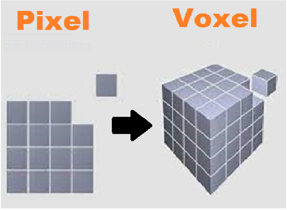