How to get Hex File from Arduino

Hello friends, hope you all are fine and having fun with your lives. In today's post, I am gonna share How to get Hex File from Arduino. It's quite a simple post and I have already explained it many times in my posts but still, I am getting a lot of messages regarding it that's why I thought to write a separate post for it. First of all, let's have a little introduction about it. If you have worked on PIC Microcontrollers or Atmel etc then you have seen that you always get hex files from their compilers and then you burn that hex file in the respective Microcontroller using their programmer or burner. But that's not the case with Arduino. In Arduino boards, you simply plug it with your computer and you hit the Upload button and the code automatically gets upload in Arduino boards. It doesn't create any hex file. You should also have a look at Arduino Library for Proteus in which you can upload this hex file.

So, now the question arises that why do we need the hex file in the first place, when we can upload the code without it? The answer to this question is, there are many cases when a hex file is required. For example, instead of using the Arduino board you just want to use the ATmega328 or Attiny microcontroller then the easiest way is to write the code in Arduino and then get its hex file and upload it in your microcontroller, which makes the task quite easy. Another example is Proteus simulation, when you want to simulate your Arduino board in Proteus software then you need to get the hex file so that you can upload it to your Arduino board. Another case is freelancing, when you are working on some project as a freelancer, then there are many cases when you don't wanna send your code to the client, instead you want to send the hex file to him so that he can test and verify the code, in such cases it also required. So let's get started with how to get hex file from Arduino.

  • Here's the video in which I have shown How to get the hex file from Arduino, I hope it will help:
Where To Buy?
No.ComponentsDistributorLink To Buy
1Arduino UnoAmazonBuy Now

How to Get Hex File from Arduino ???

  • First of all, open your Arduino software and write your code and test it.
Note:
  • If you haven't bought your Arduino UNO yet, then you can buy it from this reliable source:
  • Once you are confirmed that your code is ready and you want to generate the hex file, then click on the File option in the above menu and then Preferences as shown in below figure:
  • In the above figure, I have used the simple blink example and I am gonna generate its hex file.
  • Now when you click on the Preferences, a new window will pop up.
  • In this new window, tick the compilation option as shown in the below figure:
  • After ticking it, now click on the OK button and this dialog box will close.
Note:
  • By ticking this option you are allowing the Arduino software to show verbose outputs in the output panel present at the end of Arduino software, which has a black background.
  • So, you can also tick the upload option but then you need to upload the code to get these output commands.
  • Now hit the compile button as we tick the compilation option, so it will compile the code and will give you all the commands as shown below:
  • Now you can see clearly in the above figure that there are many commands in the black portion, these are the verbose outputs that Arduino is giving us.
  • The last line of these verbose outputs, which I have also highlighted is the link to hex file, which in our case is:

C:UserszainAppDataLocalTempbuild7243111610766241365.tmp/Blink.cpp.hex 

  • Now, remove the name of the hex file from this link and it will become:

C:UserszainAppDataLocalTempbuild7243111610766241365.tmp

  • Paste this link in the computer address bar and this folder will open up.
  • In that folder search for your respective file and you easily get the hex file of your code.
Note:
  • Actually, while uploading the code to Arduino boards, Arduino software creates the hex file of the code in the temporary folder and once the code is uploaded then it deletes that hex file.
  • That's why, we don't get the hex file, but by clicking the option you can easily get the hex file and then can use it for any purpose.

That's all for today, and I think it was quite an easy tutorial but still if you having questions then ask in the comments and I will resolve them. till next tutorial, take care!!! :)

Intelligent Energy Saving System

Hello friends, hope you all are fine and having fun with your lives. Today, I am going to share a complete project with you guys. Its an Intelligent Energy Saving System which I designed around two years ago. So, today I thought to share it so that others could also get benefit. In this project, I have used Arduino UNO board for programming purposes. Its not much complicated project but is the basic for many complex projects.

Energy, is a small word, but is the problem of whole world. Particularly when we are talking about electrical energy. IF you consume more electrical energy then you will get quite huge bill at the end of the month. :P So, there's always work done on reducing the consumption of electrical energy and also we compare energy costs from different providers. As a human, suppose you turn ON your room fan, then normally you forget to turn it OFF and thus your bill keeps on increasing. So in order to avoid this, automation is the only tool which comes in handy. Like there must be such system which automatically detects whether someone is still in the room or not and if there's no one then lights got OFF automatically. In this way, you can quite easily reduce your electricity cost. This same concept is presented in this project, let's have a complete look over it. :)

Overview of Intelligent Energy Saving System

  • In this project, we have designed a complete room and used two inductive loads i.e. bulbs and one fan.
  • Now the purpose of this project was to save the energy so we used two IR sensors for counting.
  • Now, if there's no one present in the room then the loads will automatically turn OFF and when someone will enter in the room then the loads will automatically turn ON.
  • Moreover, we have also added a counter functionality in it i.e. the project will also count the number of people present in the room.
  • All these parameters will also display on the LCD attached with Arduino.
Components Used

I am mentioning here the components used in designing this project. I am not giving the exact values as you will get them in the circuit diagrams. Here's the list:

  • Arduino UNO
  • IR Sensors
  • 16 x 2 LCD
  • 100W Bulbs
  • 12V Fan
  • 2 Relay Board
  • 7805 (IC Regulator)
  • LED (Indication)
  • Resistance
  • Capacitors

Circuit Diagrams of Intelligent Energy Saving System

Suppose you are designing this project then the first thing you are gonna need is the circuit diagrams for the project so here I am gonna show you all the circuit diagrams step by step so let's start:

1: Interfacing of Arduino with LCD
  • First thing we are gonna need is the interfacing of Arduino with LCD. LCD used in this project is 16 x 2.
  • I have first designed the simulation in Proteus as its always better to design the simulation before going into real hardware.
  • Now upload the below code into it, just to test that whether its working fine or not:
    #include <LiquidCrystal.h>
    LiquidCrystal lcd(12, 11, 5, 4, 3, 2);

    void setup()
    {

    lcd.begin(16, 2);
    lcd.print("www.TheEngineer");
    lcd.setCursor(0,1);
    lcd.print("ingProjects.com");
    }
    void loop() {}
  • Now run it and if everything's gone fine then you will get something as shown in below figure:
Note:
2: Circuit diagram of 2 Relay Board
  • Next thing we are gonna need is the two relay board. Using these relays we are gonna turn ON or OFF our loads.
  • Here's the circuit diagram for 2 relay board.
  • As you can see in the above figure, I have used two relay board, where both the relays are controlled bt simple logic operators.
  • Now instead of these logic operators, you need to give Arduino Pins here.
  • I have made the first relay ON while the second relay is OFF.
  • In the above figure, relay outputs are open so you can place anything here as its gonna act as switch. So, in our case the loads will be placed after this relay.
3: Circuit Design of Buzzer
  • Next circuit design which we need to understand is the buzzer circuit design.
  • Its quite simple and similar to 2 relay board. I have also published a detailed post on How to Design a Buzzer in Proteus ISIS, which will be quite helpful.
  • Here' I am gonna explain it lightly, so let's have a look at the circuit diagram of buzzer:
  • You can quite easily understand the above figure, where I have shown both the ON and OFF states of buzzer.
4: Circuit Diagram of IR Sensor:
  • In this project, I have used two IR sensors, both are placed on the door one after another. You can read more about the designing of IR Sensor on my post Circuit Diagram of IR Sensor using 555 Timer.
  • I have named them Entering IR Sensor and Leaving IR Sensor.
  • The logic behind these two sensors is that, when someone enters in the room then he will first pass the Entering IR Sensor and then will hit the Leaving IR Sensor and if someone is leaving the room then he will first pass the Leaving IR Sensor and then will cut the Entering.
  • So, in this way I am counting the persons if someone entering in the room I simply increment and if someone's leaving then I decrement.
  • Now, if number of people in the room becomes zero then I turn OFF all the lights and the fan, and if there even one person in the room then I turn ON the lights and fan.
  • Here's the circuit diagram of IR Sensor:
  • IR transmitter and Receiver are not available in Proteus so that's why I have used the button so when you press the button, its like someone cut the beam of IR sensor, and you will get below result:
 
5: Complete Circuit Diagram of Intelligent Energy Saving System
  • Now that we have designed the individual circuit diagrams, next thing we are gonna do is the assembly of complete project.
  • So, here's the complete circuit diagram of this project:
  • As you can see in the above figure, I have used two IR Sensors. The first IR Sensor is for entering in the room while the IR sensor is for leaving the room.
  • Next is the buzzer circuit which is also quite simple and I have explain in detail above.
  • LCD will display the no of people in a room and will also display either the bulb is ON or OFF, and also about Fan status.
  • I haven't shown the relay circuit in above figure as it will not fit in the space and I think you guys can place it easily.

Programming Code for Intelligent Energy Saving System

  • The code designed for this project is developed in Arduino software.
  • Code is as follows:
#include <LiquidCrystal.h>
#include <OneWire.h>
#include <DallasTemperature.h>
 
#define ONE_WIRE_BUS 8
OneWire oneWire(ONE_WIRE_BUS);
DallasTemperature sensors(&oneWire);
LiquidCrystal lcd(12, 11, 5, 4, 3, 2);

float celsius, fahrenheit;

int Sensor1 = A0;
int Sensor2 = A1;

int Bulb = A5;
int Fan = A4;
int Buzzer = A3;

int Counter = 0;
int Sen1Check = 0;
int Sen2Check = 0;

void setup(void) 
{
    Serial.begin(9600);
    digitalWrite(Bulb, HIGH);
    digitalWrite(Fan, HIGH);
    digitalWrite(Buzzer, HIGH);
    pinMode(Sensor1, INPUT);
    pinMode(Sensor2, INPUT);
    pinMode(Bulb, OUTPUT);
    pinMode(Fan, OUTPUT);
    pinMode(Buzzer, OUTPUT);
    
    
    lcd.begin(20, 4);
    lcd.setCursor(0, 1);
    lcd.print("Temp = ");
    lcd.setCursor(0, 0);
    lcd.print("Counter = ");
    lcd.setCursor(12, 0);
    lcd.print("Persons");
}

void loop() 
{
  CheckEntry();
  CheckLeaving();
  lcd.setCursor(7, 1);
  sensors.requestTemperatures();
  lcd.println(sensors.getTempCByIndex(0));
  lcd.setCursor(12, 1);
  lcd.print(" degC");
  lcd.setCursor(10, 0);
  if(Counter >= 0){lcd.print(Counter);}
  if(Counter < 0){Counter = 0;}
  
  if(Counter > 0)
  {
      digitalWrite(Bulb, LOW);
      digitalWrite(Fan, LOW);
      digitalWrite(Buzzer, HIGH);
      lcd.setCursor(0, 2);
      lcd.print("Fan : ON ");
      lcd.setCursor(0, 3);
      lcd.print("Bulb : ON ");
  }
  
  if(Counter < 1)
  {
      digitalWrite(Bulb, HIGH);
      digitalWrite(Fan, HIGH);
      digitalWrite(Buzzer, HIGH);
      lcd.setCursor(0, 2);
      lcd.print("Fan : OFF");
      lcd.setCursor(0, 3);
      lcd.print("Bulb : OFF");
      
  }
  

}


void CheckEntry()
{
    if(((digitalRead(Sensor1) == LOW) || (Sen1Check == 1)) && (Sen2Check == 0))
    {
        while(digitalRead(Sensor1) == LOW);
        Sen1Check = 1;
     
        if(digitalRead(Sensor2) == LOW)
        {
            Counter++;
            Sen1Check = 0;
            while(digitalRead(Sensor2) == LOW);
        }
    } 
}


void CheckLeaving()
{
    if(((digitalRead(Sensor2) == LOW) || (Sen2Check == 1)) && (Sen1Check == 0))
    {
        while(digitalRead(Sensor2) == LOW);
        Sen2Check = 1;
       
        if(digitalRead(Sensor1) == LOW)
        {
            Counter = Counter - 1;
            Sen2Check = 0;
            while(digitalRead(Sensor1) == LOW);
        }
    } 
}
  • Coding isn't much difficult for this project, but still if you get into some trouble ask in comments and I will check it out.
  • Here's the complete video for this Intelligent Energy Saving System, which will explain all about the project.
That's all for today. I hope I have helped you guys in some way. Till next tutorial, take care ALLAH HAFIZ :)

NRF24L01+ with Arduino - Response Timed Out

Hello friends, hope you all are fine and having fun with your lives. Today I am going to share a problem and also its solution with you guys. A few days ago, I bought new NRF24L01 modules as they were needed for a project. So, today when I started working on them, I encountered a very strange problem. When I interfaced my NRF24L01 with Arduino and uploaded the transmitting and receving codes in them, I couldn't get anything on my serial terminal as I explained in my previous post Interfacing of NRF24L01 with Arduino. That was quite strange for me as I have worked on this module many times and it never troubled me before. So I keep on working on it but no luck. I even changed my RF modules as I thought may be they are faulty modules but still no luck. :(

So, the next thing came to my mind is to upload the Getting Started example from the RF24 library which I have also given in my previous post Interfacing of NRF24L01 with Arduino, and now when I checked the serial terminal, I got this error:

  • Failed, response timed out.

The screenshot of this response is as follows:

As you can see in the above figure, in the last lines we are getting error that "Now sending 4679...failed. Failed, response timed out." So, that was the problem which I encountered almost for half an hour and then I finally realized what I am missing and how to solve it. Before going to the solution, let me first tell you the types of this modules.

Types of NRF24L01 Module

  • When I encountered this problem, and instead of lot of efforts and not being able to resolve it, I finally thought of using the old module, so I searched for it and luckily I found one of them.
  • So, now I plugged this new module with another Arduino and I checked the properties of both these modules (i.e. the old one and the new one) and for that I simple uploaded the below sketch in both of my Arduino boards and opened the serial terminal.
#include <SPI.h>
#include "nRF24L01.h"
#include "RF24.h"
#include "printf.h"

RF24 radio(9,10);

const uint64_t pipes[2] = { 0xF0F0F0F0E1LL, 0xF0F0F0F0D2LL };

typedef enum { role_ping_out = 1, role_pong_back } role_e;

const char* role_friendly_name[] = { "invalid", "Ping out", "Pong back"};

role_e role = role_pong_back;

void setup(void)
{
 
    Serial.begin(57600);
    printf_begin();
    
    radio.begin();
    radio.setRetries(15,15);
    
    radio.openReadingPipe(1,pipes[1]);
    
    radio.startListening();
    
    radio.printDetails();
}

void loop(void)
{
}
  • In this sketch, I simple print the details of NR24L01 module, so I uploaded the above sketch in both the Arduinos, one with old NRF24L01 module and the one with new NRF24L01 module, and I got the below response.

  • Now I got the reason that why I am not getting the response for the same code, which worked on the old one, because the old module model was NRF24L01 while this new module is NRF24L01+ which is slightly different from NRF24L01.
  • So that's the reson why I was constantly getting the Failed, response timed out error for this module. So, now lets have a look on how to resolve this issue.

How to resolve "Failed, response timed out" for NRF 24L01+ with Arduino

  • So, now one thing I knew that my module is NRF24L01+ and not NRF24L01 so I need to interface NRF24L01+ with Arduino. :)
  • So, I started looking online and get its datasheet which helped a lot and finally I got the thing.
  • NRF24L01+ draws more current than NRF24L01 while starting up and Arduino couldn't provide that required current to it. That's the reason NRF24L01+ failed to initialize and couldn't send or receive the response.
  • So, in order to remove this issue, I simply placed a Capacitor of 100uF between 3.3V and GND of Arduino and it did the magic. :)
  • Detailed circuit diagram is as follows:
  • So, that's the simple solution which kept me on for around an hour and then I finally got it.
  • As you can see in above figure, its exactly the same circuit diagram and the only addition is the capacitor placed between 3.3V and the GND.
  • After that I uploaded both the codes for receiver and transmitter which I have already posted in my old post Interfacing of NRF24L01 with Arduino and it worked like charm. :)

That's all for today, will meet you guys in the next tutorial soon. Take care!!! :)

Interfacing of LM35 with Arduino in Proteus ISIS

Hello friends, I hope you all are fine and enjoying yourself. Today I am going to share a new project titled Interfacing of temperature sensor LM35 with Arduino UNO in Proteus ISIS. So far, I have only worked on temperature sensor DS18B20 for temperature measurements and I have also uploaded a tutorial on Interfacing of Temperature Sensor 18B20 with Arduino.

Recently I got a chance to work on a project regarding temperature sensing but the condition of this project was that to use only LM35 for temperature detection. Then, I get to know much about LM35, its operating conditions and features. So I thought I should also upload its tutorial as it will also be advantageous for engineering students. Because learning new things is always a charm.

An excellent thing about LM35 is that it's quite cheap as compared to other temperature sensors. And as it's cheap, that's why it's not very reliable, if you personally ask me then I will prefer DS18B20 over LM35 because of its accurate readings. Now, let's move towards its interfacing and its practical applications. First of all, let's have a quick look at the introduction of LM35 and then we will design it in Proteus ISIS.

Where To Buy?
No.ComponentsDistributorLink To Buy
1LM35AmazonBuy Now
2Arduino UnoAmazonBuy Now

Introduction of LM35 Temperature Sensor

  • LM35 is an embedded sensor, used to measure the temperature of its surroundings and is famous because of its low cost.
  • Its output is generated in the form of an Electrical signal and this electrical signal is proportional to the temperature, which it detects.
  • Lm35 is much more sensitive than other temp measuring devices (not accurate).
  • The internal circuitry of this embedded sensor is sealed inside a capsule.
  • LM35 is a 3 pin IC and it is used for temperature detection. The physical appearance of LM35 is shown in the image given below:

  • As you can see in the above image that LM35 is a 3 pin IC:
    1. The first pin is Vcc, so it should be connected to 5V.
    2. The center pin is its Data Pin and LM35 gives its output when it measures temperature.
    3. The third pin is GND and should be connected to the ground of the battery/source.

LM35 Arduino Interfacing

  • As my today's tutorial is about interfacing LM35 with Arduino so let's start it.
  • I have connected LM35 with Arduino microcontroller and it is shown in the image given below:

  • As you can see in the above image, I have connected an LM35 sensor with Arduino UNO.
  • The VCC pin of LM35 is connected to +5V of the Arduino board.
  • Since LM35 generates an analog value at its output pin that's why I have connected this pin to the 'A0' pin of the Arduino board.
  • This pin of Arduino board is used to receive analog data from an external source.
  • And the last pin is connected to the GND pin of the Arduino board.

Arduino Code for LM35

  • After connecting the circuit, now upload the below code to your Arduino board.
#define TempPin A0

int TempValue;

void setup()
{
  Serial.begin(9600); // Initializing Serial Port
}
void loop()
{
  TempValue = analogRead(TempPin); // Getting LM35 value and saving it in variable
  float TempCel = ( TempValue/1024.0)*500; // Getting the celsius value from 10 bit analog value
  float TempFarh = (TempCel*9)/5 + 32; // Converting Celsius into Fahrenhiet

  Serial.print("TEMPRATURE in Celsius = "); //Displaying temperature in Celsius
  Serial.print(TempCel);
  Serial.print("*C");
  Serial.print("    |    ");

  Serial.print("TEMPRATURE = "); // Displaying Temperature in Fahrenheit
  Serial.print(TempFarh);
  Serial.print("*F");
  Serial.println();
  
  delay(1000);

}

LM35 Arduino Simulation in Proteus ISIS

  • Now let's do this project in Proteus. Proteus also has an LM35 sensor in its database which we are going to use here.
  • Moreover, we also know about Arduino Library for Proteus V2.0, so using that library we are going to interface LM35 with Arduino in Proteus ISIS.
  • First of all, design the same circuit as shown in the above figure in Proteus software as shown below:
  • It's the same circuit as we designed before, the only addition is the virtual terminal. We are using it to check the values.
  • It's simply like the Serial Monitor we use in Arduino software.
  • So, now using the above code, create the hex file and upload it in Proteus.
  • Now hit run and if everything goes fine then you will get results as shown in the below figure:
  • You can see the Virtual Terminal is showing the same value as shown on the sensor which is 33 in Celsius and later I converted it to Fahrenheit.
It's quite simple and I have also commented on the code but still if you find trouble then ask in comments and I will resolve them. Will meet in the next tutorial, till then take care!!! :)

Circuit Diagram of IR Sensor using 555 Timer

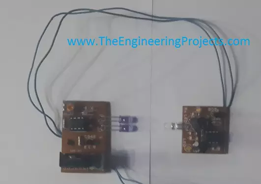
Hello everyone, hope you all are fine and having fun with your lives. Today's tutorial is quite simple and we will have a look at circuit diagram of IR sensor using 555 Timer. There are different types of IR sensors available in the market. IR is abbreviation of infrared and so they use infrared ray for detection of objects. There are many types of IR sensors with different functionality, but in all of them infrared rays are omitted from transmitter and are received by the receiver. and using these ray we can say whether an object is placed in the path or not.

Today we are gonna see how to design your own IR sensor using 555 Timer. We can also interface these IR sensors quite easily with any microcontroller like PIC Microcontroller , Arduino etc. I was also thinking of designing it in Proteus but Proteus doesn't have the IR leds in it so I couldn't do it. IR sensors available in market are quite costly ranging from 10$ to 100$ obviously they are also excellent in efficiency but in engineering cost efficiency also plays an important role so today we are gonna have a look at circuit diagram of IR sensor using 555 timer which will cost you just $2. Before going into the details, lets first have a look at types of IR sensors.

Types of IR sensors

  • There are normally two types of IR sensors available in market.
First Type of IR Sensors:
  • First type is transceiver IR sensor which has both transmitter and receiver in it. This type of IR sensor is used to detect the distance of object from the sensor.
  • In this type of IR sensors, rays are omitted from the transmitter and are reflected back after hitting some object and are captured by the receiver.
  • On the basis of the time taken by these rays to reflected back, we calculate the distance of the object from the sensor.
Second Type of IR Sensors:
  • In these types of IR sensors, transmitter and receiver are not on same chip but on seperate pieces.
  • These types of IR sensors are used for detection of object.
  • For example we need to count people entering in some room then we will place this IR sensor on the door of that room with transmitter on one end and receiver on the other.
  • So, now when some one will enter through the door , he will cut the IR beam and thus the IR light wont be received by the receiver and thus the sensor will know that someone entered.
  • These types of IR sensors are also used in electronic devices like TV remote etc.
In this tutorial we are gonna design this second type of IR sensor using 555 timer. so, lets get started.

Circuit Diagram of IR Sensor using 555 Timer

  • So, here we are gonna design the second type of IR sensor using 555 timer.
  • In this sensor we need to design both the transmitter and the receiver.
  • So, lets get started the transmitter.
  • Design the below circuit on some circuit board:
  • In the above circuit diagram of IR sensor, I have clearly mentioned all the values of components so that you can easily design it. Moreover there are two leds used in it, these are not simple leds. There are IR leds which emits IR rays. the range of this sensor will depend roughly on the number of leds you are gonna use here, as I used two leds.
  • So, now lets have a look at circuit diagram of receiver side.
  • On this side we have use IR led but that one is receiving and will received that IR rays coming from the transmitter IR leds.
  • These are quite simple in designing and you can design it without any trouble. Before going into PCB, its better if you first design them on some wero board or bread board.
  • Here's a manufactured piece of the above given circuit diagrams. The one with two leds is the transmitter and the other one is receiver.
 
  • The image is a bit blur, coz I was in a bit of hurry but they work perfectly fine. :)
  • That's all for today, will see you guys in the next tutorial. Till then take care!!!

Traffic Signal Control using Arduino

Hello friends, hope you all are fine and having fun with your lives. Today, I am going to share a Traffic Signal Control using Arduino. Few days earlier, I have posted the same tutorial but it was Traffic Light Signal Using 555 Timer in Proteus ISIS and today we will do the same thing but using Arduino programming. Its quite a simple but good starting project on Arduino. So, if you are new to Arduino then must give it a try.

Traffic Signal Control is quite a usual thing. We see traffic signals daily on our roads and usually engineers are asked to design such projects in their initial semesters. If we look at the traffic signals then we can see they are simply turning ON and OFF lights at some fixed regular intervals. and the pattern is quite simple as well. so I have simply followed that pattern and design the code. You should also have a look at Arduino 3 Phase Inverter. So let's start with designing this project named as Traffic Signal Control using Arduino.

Traffic Signal Control using Arduino

  • First of all, design a circuit in Proteus for Traffic Signal Control using Arduino as shown in the below figure:
  • Its quite a simple project so the circuit is quite simple as well. You can see I have just placed an Arduino board and plugged three LEDs with it and obviously they are Green, Yellow and Red in color.
  • These LEDs are attached to pins 2,3 and 4 of Arduino UNO.
  • Now next step is to write the Arduino Code for Traffic Signal Control using Arduino, so I have written and it is shown below:
#define GreenLed 4 #define YellowLed 3 #define RedLed 2 void setup() { pinMode(GreenLed, OUTPUT); pinMode(YellowLed, OUTPUT); pinMode(RedLed, OUTPUT); } void loop() { digitalWrite(GreenLed, HIGH); digitalWrite(YellowLed, LOW); digitalWrite(RedLed, LOW); delay(5000);delay(5000); digitalWrite(GreenLed, LOW); digitalWrite(YellowLed, LOW); digitalWrite(RedLed, HIGH); delay(5000);delay(5000); digitalWrite(GreenLed, LOW); digitalWrite(YellowLed, HIGH); digitalWrite(RedLed, LOW); delay(3000); }
  • That's the complete code for this project Traffic Signal Control using Arduino and I think its quite self explanatory plus I have also changed the color accordingly.
  • First of all Green LED is ON and the rest are OFF which is shown in green color.
  • Next Red LED is ON and the rest are OFF after around 10 seconds which you can change by changing these delays.
  • Finally the Yellow LED will be ON and you can see it goes OFF just after 3 sec because it has short delay, you can change these delays quite easily.
  • Below is the flow chart of above programming for Traffic Signal Control using Arduino which will clear the theme properly.
  • Now compile your Arduino code and get the hex file.
Note:
  • Now when you upload the hex file into your Arduino, it will give output as shown below:
  • So that's how it will work, I hope you got this clearly as its quite simple, will meet you soon in the next tutorial. Till then take care!!! :)

Interfacing of RFID RC522 with Arduino

Hello friends, hope you all are fine and having fun with your lives. Today's post is about interfacing of RFID module RC522 with Arduino. RC522 is very simple yet effective module. It is an RFID module and is used for scanning RFID cards. Its a new technology and is expanding day by day. Now-a-days it is extensively used in offices where employees are issued an RFID card and their attendance is marked when they touch their card to rfid reader. We have seen it in many movies that when someone places ones card over some machine then door opens or closes. In short, its a new emerging technology which is quite useful.

I recently get a chance to work on a project in which I have to use RFID reader to scan cards. In this project I have used it for for student attendance so I thought to share it on our blog so that other engineers could get benefit out it.

Let's first have a little introduction of RFID and then we will look into how to interface RC522 with Arduino. RFID is the abbreviation of Radio frequency identification. RFID modules use electromagnetic fields to transfer data between card and the reader. Different tags are attached to objects and when we place that object in front of the reader, the reader reads that tags.Another benefit of RFID is that it doesn't require to be in a line of sight to get detected. As in barcode, the reader has to be in the line of sight to the tag and then it can scan but in RFID there's no such restriction. So, let's get started with Interfacing of RFID RC522 with Arduino.

You should also read:

Interfacing of RFID RC522 with Arduino.

Now let's start with the interfacing of RFID RC522 with Arduino. There are many different RFID modules available in the market. The RFID module, which I am gonna use in this project, is RFID-RC522. Its quite easy to interface and works pretty fine. This module has total 8 pins as shown in the below figure:

  • SDA
  • SCK
  • MOSI
  • MISO
  • IRQ
  • GND
  • RST
  • 3.3V
It normally works on SPI protocol, when interfaced with Arduino board. Interfacing of Arduino and RC522 module is shown in below figure:
  • The pin configuration is as follows:
  • Now, I suppose that you have connected your RFID module with Arduino as shown in above figure and table, which is quite simple. You just need to connect total 7 pins, IRQ is not connected in our case.
  • Now next step is the coding, so first of all, download this Arduino library for RFID RC522 module.
Note:
  • Its a third party library, we haven't designed it, we are just sharing it for the engineers.

  • Now coming to the final step. Upload the below code into your Arduino UNO.
#include <SPI.h> #include <MFRC522.h> #define RST_PIN         9 #define SS_PIN          10 MFRC522 mfrc522(SS_PIN, RST_PIN); void setup() { SPI.begin(); mfrc522.PCD_Init(); } void loop() { RfidScan(); } void dump_byte_array(byte *buffer, byte bufferSize) { for (byte i = 0; i < bufferSize; i++) { Serial.print(buffer[i] < 0x10 ? " 0" : " "); Serial.print(buffer[i], HEX); } } void RfidScan() { if ( ! mfrc522.PICC_IsNewCardPresent()) return; if ( ! mfrc522.PICC_ReadCardSerial()) return; dump_byte_array(mfrc522.uid.uidByte, mfrc522.uid.size); }
  • Now using this code, you can read the RFID no of your card quite easily. Now the main task is to use that number and distinguish them so for that I changed the dump_byte_array function a little, which is given below:
#include <SPI.h> #include <MFRC522.h> #define RST_PIN         9 #define SS_PIN          10 MFRC522 mfrc522(SS_PIN, RST_PIN); int RfidNo = 0; void setup() { SPI.begin(); mfrc522.PCD_Init(); } void loop() { RfidScan(); } void dump_byte_array(byte *buffer, byte bufferSize) { Serial.print("~"); if(buffer[0] == 160){RfidNo = 1;Serial.print(RfidNo);} if(buffer[0] == 176){RfidNo = 2;Serial.print(RfidNo);} if(buffer[0] == 208){RfidNo = 3;Serial.print(RfidNo);} if(buffer[0] == 224){RfidNo = 4;Serial.print(RfidNo);} if(buffer[0] == 240){RfidNo = 5;Serial.print(RfidNo);} Serial.print("!"); while(1){getFingerprintIDez();} } void RfidScan() { if ( ! mfrc522.PICC_IsNewCardPresent()) return; if ( ! mfrc522.PICC_ReadCardSerial()) return; dump_byte_array(mfrc522.uid.uidByte, mfrc522.uid.size); }
  • Now using the first code I get the card number for all RFID cards and then in second code I used these numbers and place the check now when first card will be placed it will show 1 on the serial port and so on for other cards.
  • So, what you need to do is to use the first code and get your card number and then place them in second code and finally distinguish your cards.
  • Quite simple and easy to work.
  • Hope I have explained it properly but still if you get any problem ask me in comments.

NRF24L01 Arduino Interfacing

Hello friends, I hope you all are fine and enjoying. I have been working on a project these days and one portion of my current project includes the NRF24L01 Arduino Interfacing. So, I thought why not share this knowledge with you people, I hope you will learn something new and more interesting. If you don't know much about it, then you should have a look at Introduction to NRF24L01.

Few days ago, I have also posted a tutorial on XBee Arduino Interfacing, in which we have seen how to make wireless communication between two XBee Modules which is also an RF module. So, now we are gonna have a look at How to make Wireless Communication between two NRF24L01 modules. I hope you are gonna enjoy this nrf24l01 arduino Interfacing. Here's the video demonstration of NRF24L01 Arduino Interfacing:

Basics of NRF24L01

Before staring this interfacing of Arduino with 24L01, lets have a little introduction of nrf24l01 module. NRF24L01 is, in fact, a Radio Transceiver module and it operates on 2.4 GHz frequency. This module is a by default half- duplex fabricated module and it has the capability to send and receive data simultaneously. It's a very cheap & small sized module but it's features are astonishing. For example this module is capable of sending from 1 to 25 bytes of raw data simultaneously and the data transmission rate is up to 1 mega bytes per second. If we summarize all the features of this small size but big capability module then, we can say that:

  • By using this NRF24L01 module we can send a message to a particular receiver.
  • We can receive a message from some particular sender. (remember as I told earlier, we can do both the steps simultaneously).
  • During sending the message through this module, we will have to specify the message sender's and receiver's address.
  • Also we will have to specify the size of that particular message, which we are going to transmit through this module.
  • In some particular applications, we also have to perform switching between the receiver and sending state. For example, if you are received a particular message then, we will stop the communication first and will read it and then you will send it. So in such situations, we have to perform the switching while sending or receiving data through this module.
Now above discussion was a brief introduction about NRF24l01 module. Now lets move towards the major theme of our project which is Interfacing of arduino with NRF24l01 module. Note:
  • I encountered a problem of "Failed, response timed out" with NRF24L01+ while interfacing it with Arduino, if you got the same problem then read this post Interfacing of NRF24L01+ with Arduino - Response Timed Out. This nrf24l01 arduino example will help you in understanding this Response Timed Out problem.

NRF24L01 Arduino Interfacing

Arduino is a very powerful and versatile microcontroller board and it gives us the ease to perform multitasking. NRF24l01 has total 8 pins. The pin configuration and the function of each pin is described below:
  • The very first pin is for GND and through the pin#1 of this module, ground is provided to module.
  • Pin#2 of this module is to provide power supply. This pin is designated as VCC. This module generally needs 1.9 to 3.6 volts for its operation. And in most cases we will apply 3 volts to it.
  • Pin#3 is designated as CE and it is used to select the mode of operation. Either you are using this module to transmit data or to receive data.
  • Pin#4 is designated as CSN and it is used to enable the SPI chip, embedded on the module.
  • Pin#5 is used to provide SPI clock to the module. When this pin is HIGH then, clock is enabled and when this pin is LOW then, the clock to this module is disabled.
  • Pin#6 is designated as MOSI and it is used to transmit data from this module to the external circuit.
  • Pin#7 is designated as MISO and if we wish to receive data through this module from any external source then, this pin is enabled.
  • Pin#8 is the last pin of this module and it is designated as IRQ pin.
In order to do this Arduino with NRF24L01 communication, you will need two Arduino boards and two NRF24L01 modules. Now I suppose that you have these 4 items in your hand. So, first of all, let's do the transmitter side of NRF24L01 Arduino Interfacing.
NRF24L01 As Transmitter
  • Connect your NRF24L01 with Arduino as shown in the below figure:
  • Total 7 pins of NRF24L01 will be connected while the 8th pin IRQ doesn't need to connect.
  • Now, next thing you need to do is to download this RF24 Library of Arduino and place it in the libraries folder of your Arduino software so that we could compile our code of nrf24l01 arduino example.

Arduino Library for NRF24L01

  • We haven't designed this library, we are just sharing it for the engineers to use it in their projects.
  • Now upload the below sketch into your Arduino which you want to act as Transmitter.
    #include <SPI.h>
    #include "nRF24L01.h"
    #include "RF24.h"

    RF24 radio(9,10);

    const uint64_t pipes[2] = { 0xF0F0F0F0E1LL, 0xF0F0F0F0D2LL };
    unsigned long Command = 1;
    void setup()
    {
    Serial.begin(57600);

    radio.begin();
    radio.setRetries(15,15);
    radio.openReadingPipe(1,pipes[1]);
    radio.startListening();
    radio.printDetails();
    radio.openWritingPipe(pipes[0]);
    radio.openReadingPipe(1,pipes[1]);
    radio.stopListening();
    }

    void loop(void)
    {
    radio.stopListening();

    radio.write( &Command, sizeof(unsigned long) );

    radio.startListening();

    delay(1000);
    }
  • In this code, I have marked the variable Command, this is the variable which I am sending via NRF24L01, rite now its value is 1 which you can change.
  • So, if you want to send 3 you can change its value to 3.
  • Now lets design the receiver side.
NRF24L01 As Receiver
  • Again connect your Arduino with NRF24L01 as shown in below figure. Its same as we did for Transmitter side.
  • Now upload this below code into the Receiver and you will start receiving the value coming from transmitter.
    #include <SPI.h>
    #include "nRF24L01.h"
    #include "RF24.h"

    RF24 radio(9,10);

    const uint64_t pipes[2] = { 0xF0F0F0F0E1LL, 0xF0F0F0F0D2LL };

    typedef enum { role_ping_out = 1, role_pong_back } role_e;

    const char* role_friendly_name[] = { "invalid", "Ping out", "Pong back"};

    role_e role = role_pong_back;

    void setup(void)
    {
    Serial.begin(57600);
    radio.begin();
    radio.setRetries(15,15);
    radio.openReadingPipe(1,pipes[1]);
    radio.startListening();
    radio.printDetails();
    radio.openWritingPipe(pipes[1]);
    radio.openReadingPipe(1,pipes[0]);
    radio.startListening();
    }

    void loop(void)
    {

    if ( radio.available() )
    {
    unsigned long data = 0;
    radio.read( &data, sizeof(unsigned long) );
    Serial.println(data);

    delay(20);
    }
    }
  • Now open your Serial Monitor of Receiver side and you will see that you are getting "1" in the Arduino Serial Monitor, which is the value of Command variable we set in the Transmitter side, as shown in below figure:
  • Its quite easy and I hope you will make it work in the first attempt but if you still got problem then ask in comments.
  • I will share more Arduino Projects on this RF module soon.
So, that's all for today and I hope now you can easily Interface Arduino with NRF24L01 and can do the RF communication. If you have any problem in this Interfacing of Arduino with NRF24L01 then ask in comments and I will try my best to resolve them. Take care. :)

Getting Started with Arduino Programming

Hello friends, i hope you all are fine enjoying. Today i am going to share a new project tutorial which is Getting Started with Arduino Programming. In the previous tutorial, which was titled as Getting started with Arduino Software, I have explained in detail the basics of Arduino software. How this software is installed and run.

Today's post is also related to arduino software but, the difference is that, in previous post we learn How to use the arduino software, What are the function keys of this software and Where to write the code(sketch) and after writing the sketch, how it is debugged. Now in today's post which is ' Getting started with Arduino Programming', we will see How a Code is written in Arduino software? What are the built-in functions of Arduino software? How comments are made in sketch? What are the main loops, used in Arduino programming? How pin selection is done in Arduino software? How Digital pins are controlled, which are embeded on Arduino board? To explain this whole software in detail, i have divided this tutorial into major parts and also their sub-parts. Above was a little introduction about what actually we are going to learn in this post. Now without wasting any further time on introduction (as i will be explaining each and every step in below tutorial) i think now we should move towards the actual learning of the Arduino software to use it for programming.

You should also read:

1- How to make Comments in Arduino Programming

  • I hope that you are a beginner and i will start to elaborate the soaftware from very beginning.
  • First of all open your Arduino software. Go to file menu, a new window will open, from there click on the Examples and then go the Basics.
  • After clicking on basics a third new window will open and it will be showing all the basic Arduino built-in basic functions.
Note:
  • If you haven't bought your Arduino UNO yet, then you can buy it from this reliable source:

  • For beginners the function named as blink is very useful, so i will also teach you from this basic level tutorial.
  • When you will click on 'blink' option then, a new window will open, which is shown in the image given below:
  • In the above shown image you can see that we have opened a basic level example from built in Arduino software.
  • Now under this heading title, i will explain how to make comments in Arduino programming?
  • This is in fact the syntax to make comments in your sketch.The above code is of very basic level and it elaborates how to blink a single led by using Arduino board.
  • If you look closely in the above image then you will see that some words are written in the start of the sketch and these words are encloses in these signs " /* ..........*/ ".
Note: Comments have no rule in sketch, neither they are as necessary to write in every sketch. We only add them in code to make the code user friendly or to make the user understand that what actually in happening in the code.
  • An other way to add the comments is to write " // .........." before every line in your sketch.
  • When you will do that before any particular line then, that line will become green and it will no longer have any effect in the sketch.
  • There is also a little difference in these both techniques of making comments.
  • First technique is used at that place where we have to write 3 or 4 lines together, or a large paragraph is to introduced in the sketch to make the user understand the sketch. We don't have make every line comments one by one. So, this method of making comments gives us ease.
  • While the second technique is used at that place, where we have to make comments in a single line.
  • Both these techniques have there own purposes and are used at that place where, we wish to use them.

2- Main Loops In Arduino Programming

  • Now the next step in learning Arduino programming is to learn about the main loops, which are used in Arduino programming.
  • To see what are the main loops, you simply go to the file menu and click on the new button and a second new window will open, which is shown in the image given below:
  • Above image is showing the main loops, which are used in Arduino software while programming.
  • The first loop is 'void setup' and the second loop is 'void loop'.
  • The syntax to write these both loops is also shown in the above image. But you should don't worry about the syntax of these loops because the good news is that the software it-self generated the syntax, when you open a new file to write the sketch.
  • Void setup is the first and the main loop while programming in Arduino. It is used for initialization and for configuration of constant values.
  • For example while writing a sketch if you are gonna need some constant values in your code then, it is necessary that you must initialize them first in this loop.
  • If you didn't initialize those constants first then, code will not execute properly and it will generate error.
  • The other main loop which is used while using programming in Arduino is "void loop", as you can also see it from the above given image.
  • An important thing to note here is that the compiler checks each and every line one by one in steps.
  • The compiler moves from top to bottom and in the first step, it will read every line of the " void setup() " and then it comes to the " void loop() " and it reads/compiles every line written in this portion.
Note: An important thing to remember here is that, the compiler reeds ' void setup() ' loop only once and on the other hand it reeds the second loop, named as ( void loop() ) again and again.
  • So from the above given info, we can conclude that ' void loop() ' is similar to ' while(1) ' loop, which is in fact an infinite loop.

3- Pin Mode Selection in Arduino Programming

  • In the above two portions of the today's tutorial we have seen, How to make comments while doing programming in Arduino software and secondly What are the main loop being used in Arduino programming.
  • Now we are going to the third stage which is Pin Mode selection in Arduino programming.
  • If you are aware of the other micro controllers like ATmel series, PIC or AVR, then you may also know that the pin configuration of these micro controllers are fixed.
  • Which means you have pre-decided input and output pins of the micro controller. Those micro controllers have definite pins for inputs and also for outputs and they can only be used for that specific purpose.
  • For example if a micro controller have a input port then all the pins on that port will be used to receive data and you can't use them to send data.
  • While working with Arduino micro controller gives us a flexibility that every I/O pin available on the board (except for some definite pins like VCC,GND, etc) can be used as input or output pin.
  • For example if we wish to connect a led at the pin#2 of our Arduino board, which means we are going to make this pin#2 as a output pin.
  • For Arduino board we will send data to this pin through our code, which means we have made this pin as an output pin.
  • The syntax to write command to do this function is:
pinMode (2 , OUTPUT)
  • By writing this command in the code, we have made pin#2 as a output pin.
  • And if we connect some kind of sensor at this port and we have to take the value of that sensor as an input then, we will have to make pin#2 as an input pin.
  • In order to make the same pin as an input pin, we will have to write the command in the following syntax:
pinMode (2 , INPUT)
  • By writing this command, Arduino board will automatically made the pin#2 as an output pin.
  • Pull-up criteria is also very important in writing any commands for Arduino board.
  • There is only one problem with all the Arduino boards that, we whenever an un-initialized pin is used in our code then the Arduino board send some garbage value to that particular pin.
  • To overcome this problem we have to set some particular value for each and every pin. and we ahve to define state of every pin that either it is HIGH or LOW.
  • For example we can say that the function of pin#3 is that GND is always connected to that pin and if ground is not available at any case then we will send +5V to that pin to keep that pin in a particular position.
  • The Arduino board command for pull-up purpose is:
pinMode(2 , INPUT_PULLUP);
  • This command will automatically decide the particular value of every pin.

4- Digital Pins Controlling in Arduino Programming

  • Now the fourth part of the today's tutorial in learning of Arduino Programming is How digital pins are controlled while coding in Arduino.
  • Arduino board is a multi purpose micro controller and it is also capable of sending and receiving data from Digital as well as Analogue data.
  • It is our choice to make every pin as an input or output pin and similarly either it has to send or receive Digital data or it has to send or receive analogue data.

I/P Digital Pins:

  • For example, i wish to make my pin#2 as an Digital input pin, which means it will read digital data from some external source.
  • The command to do this function is given below as:
digitalRead(2); boolean sensor=digitalRead(2);
  • The first command is teeling the Arduino compiler to make pin#2 as a digital pin and the compiler will take Digital input data from that pin.
  • While the second command i have written is to save the command in a variable.
  • In this command i have introduced a datatype named as 'boolean' . You can also change the name of this datatype.
  • And the name of the variable is 'sensor'. I have kept the name 'sensor' and you can also change this name according to your own choice.

O/P Digital Pins:

  • Next if you wish to make these pins as an output pins then we can also do that.
  • Suppose now if you want to make your pin#2 as an output pin and you wish to send data to this pin or you want to define the state of this pin then the commands, which you will write are:
digitalWrite(2,HIGH); digitalWrite(2,LOW);
  • In the syntax of writing the command, we will first write no of the pin and then we write it's state.
  • The first command is showing that we are writing digital data on our pin#2 and we are going to set it in HIGH/ON state.
  • The second command shows that we are going to set the pin#2 in OFF state.

5- Analogue pins controlling in arduino programming

  • In this section of the tutorial we are going to see how to control the Analogue pins of an Arduino board.

I/P Analog Pins:

  • As i have explained above in detail that how we can digitally take or send data using Arduino pins.
  • An interesting feature is that Arduino board pins can also be used to send or receive data in an analog pattern.
  • Since my heading is to input analog data, to understand this pattern suppose that you are going to read some analog voltage from pin#2 of arduino board.
  • In order to do that, the commands which you will write in Arduino software are as:
analogRead(2); int sensor Value = analogRead(2);
  • As you can see that the syntax to read Digital and Analog Data is same.
  • In first command i am reading the analog data from external source at pin#2 of arduino board.
  • In the next command i have stored that data into a variable named "sensor value" .
  • After that all the analog data which will appear at pin#2 will be stored in 'sensor value'.

O/P Analog Pins:

  • Now if we wish to use the pins of Arduino board as an output pins then it is also very easy and you can also do that by following some simple steps.
  • If you wish to use any pin to write data or we can say that you wish to turn a switch ON or OFF then, the syntax will be as:
analogWrite (3,HIGH); analogWrite (3,LOW);
  • The first is showing that a switch has been connected at pin#3 and you wish to turn it ON and you will write the first command in Arduino sketch.
  • The second command is showing that a switch is already in ON state, which is connected at pin#3 and we wish to turn it OFF then, we will write the second command in our Arduino sketch.
Alright friends, today's tutorial was a little bit lengthy but very informative for beginners who are keen to learn Arduino software. If you have any questions then, ask in comments and i will try my best to solve the problem. Till next tutorial take care !!! :)

Interfacing PIR sensor with Arduino

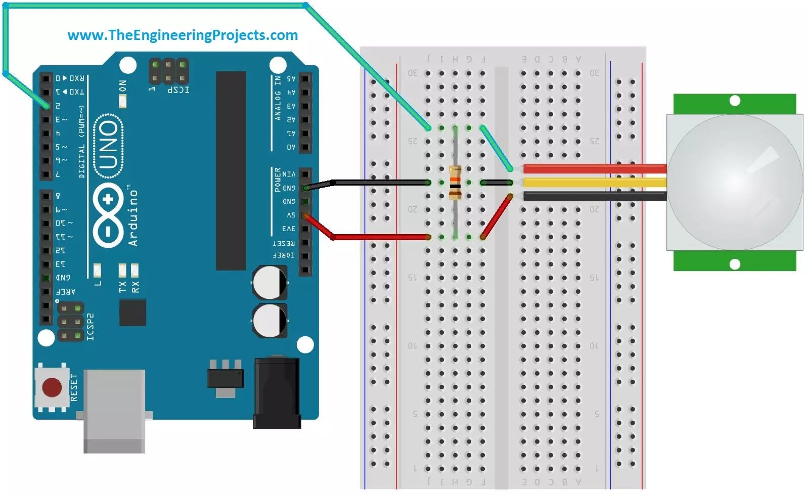
Hello friends, i hope you all are fine and enjoying. Today i am going to share a new project tutorial which is Interfacing PIR sensor with Arduino. First of all lets, have a little introduction about the basics and working of the PIR sensor. PIR sensors are in fact a Passive Infrared Sensor. PIR sensors are actually electronic sensors and they are used for motion detection. They are also used to detect the Infrared waves emitting from a particular object. You should also have a look at PIR Sensor Library for Proteus, using this library now you can easily simulate your PIR Sensor in Proteus software.

PIR sensors are widely used in motion detection projects now a days. Since my today's tutorial is about interfacing of PIR sensor with Arduino micro controller. Before going to that it is necessary that we should first understand the construction and working principle of PIR sensor. So i am going to divide my tutorial into different blocks and i will describe PIR sensor from its construction to practical applications. So first of all, lets see the construction and operating principle of PIR sensor.

Construction of PIR sensor

The construction of PIR sensor is very simple and easy to understand. In the bottom or you can say in the core of the PIR sensor we have a set of sensors which are made of pyro-electric materials. The properties of this material is that when this material is exposed to heat then, it generates energy. Different methods are used to to measure this energy generated by PIR sensor. On the top of the PIR sensor and above the internal sensors we have a small screen through which infrared radiations enters into sensor. When these radiations falls on the pyro-electric material then it generates energy. Generally the size of this sensor is very small and it is available in the form of thin film in market. Many other materials are also used in collaboration with pyro-electric material like galliam nitrite and cesium nitrate and all these materials take the form of an small integrated circuit.

Operating Principle of PIR sensor

The modern studies in the field of quantum physics tells us the fact each and every object when it is placed at a temperature above absolute zero, emits some energy in the form of heat and this heat energy is in fact the form of infrared radiations.  So an other question comes into mind that why our eyes can't see these waves? It is because that these waves have infrared wavelengths and his wavelength is invisible to human eyes. if you want to detect these waves then, you have to design a proper electronic circuit.

If you see closely the name of PIR sensor which is Passive Infrared Sensor. Passive elements are those elements that don't generate their own voltages or energy. They just only measures things. So we can say that this sensor is a passive infrared sensor and it doesn't generate anything by itself. It is only capable to measure the rediations emitted by other objects around it. It measures those raditions and do some desired calculations on them.

Interfacing of PIR Sensor with Arduino

PIR sensor have total 3 pins. The configuration of each pin is shown in the image given below:
  1. Pin#1 is of supply pin and it is used to connect +5 DC voltages.
  2. Pin#2 is of output pin and this pin is used to collect the output signal which is collected by PIR sensor.
  3. Pin#3 is marked as GND pin. This pin is used to provide ground to internal circuit of PIR sensor.
This whole configuration is also shown in the image given below:

The pin configuration of a PIR sensor is shown in the image given above. Since we have to interface the PIR sensor with Arduino micro controller. The image showing the interfacing of PIR sensor with Arduino is shown below as:

Interfacing Code

The code for interfacing Arduino micro controller with PIR sensor is given below as:
    #define pirPin 2

    int calibrationTime = 30;
    long unsigned int lowIn;
    long unsigned int pause = 5000;
    boolean lockLow = true;
    boolean takeLowTime;
    int PIRValue = 0;

    void setup()
    {
    Serial.begin(9600);
    pinMode(pirPin, INPUT);
    }

    void loop()
    {
    PIRSensor();
    }

    void PIRSensor()
    {
    if(digitalRead(pirPin) == HIGH)
    {
    if(lockLow)
    {
    PIRValue = 1;
    lockLow = false;
    Serial.println("Motion detected.");
    delay(50);
    }
    takeLowTime = true;
    }

    if(digitalRead(pirPin) == LOW)
    {

    if(takeLowTime){lowIn = millis();takeLowTime = false;}
    if(!lockLow && millis() - lowIn > pause)
    {
    PIRValue = 0;
    lockLow = true;
    Serial.println("Motion ended.");
    delay(50);
    }
    }
    }

Applications of PIR sensor

PIR sensors possess a no of applications and due to their low cost and much advanced features they are the main focus of different projects being made now a days. Some of their features and practical applications are listed below as:

  • They are able to sense the detection of people and other objects.
  • PIR sensors are also used in automatic lightening systems. In these type of systems, when a person comes in the vicinity of the sensor then, the lights are automatically turned ON.
  • They are used in outdoor lightening systems and also in some lift lobbies. You may have observed that when a person comes in front of the lift and if the doors are being closed then, the doors are opened again. This is all due to PIR sensors.
  • They are widely used in underground car parking system. At every parking position a PIR sensor is installed and when that position is vacant then, a green light glows over that place which means you can park here. And if that position has been occupied then, a red light will glow, representing that this position is already occupied.
  • PIR sensor is much compatible sensor and it has the ability to detect a particular motion and the output of this system is very sensitive and doesn't have any kind of noise in it.
Alright friends, that was all from today's post. If you have any questions, fell free to ask. Till next tutorial Take Care!!! :)  
Syed Zain Nasir

I am Syed Zain Nasir, the founder of <a href=https://www.TheEngineeringProjects.com/>The Engineering Projects</a> (TEP). I am a programmer since 2009 before that I just search things, make small projects and now I am sharing my knowledge through this platform.I also work as a freelancer and did many projects related to programming and electrical circuitry. <a href=https://plus.google.com/+SyedZainNasir/>My Google Profile+</a>

Share
Published by
Syed Zain Nasir