Introduction to 1n4738a

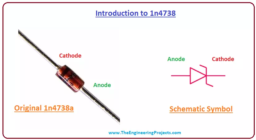
Hi Guys! Hope you are doing well. I am back to give you nuggets of valuable information related to engineering and technology so you can excel and grow in your relevant field. Today, I'll unlock the detailed Introduction to 1n4738a. It is a zener diode that comes with high power rating and is mainly used in stabilizing and clipping circuits. The zener diode is slightly different from regular diode as former can conduct in both directions while later conducts in one direction only. It is available in double slug construction with corrosion resistant surfaces, helping to operate it under high temperature and pressure. I'll try to cover each and everything related to this diode, so you don't have to grapple your mind surfing the whole internet and find all the information in one place. Let's jump right in and get down to the nitty-gritty of 1n4738a.

Introduction to 1n4738a

1n4738a is a zener diode that comes with an ability to conduct in both directions. It is a high power device mainly used in stabilizing and clipping circuits.
  • This zener diode features maximum lead temperature for soldering around 230 C. It comes with a zener voltage around 8.2 V and external leads are attached with the body, helping thru-hole mounting.
This zener diode is nothing but a p-n junction diode with current capability conducting in both directions i.e. forward direction and reverse direction, featuring very effective working characteristic with a power dissipation of around1300 mW.
  • You can not make it work in a reverse biased condition unless reverse breakdown voltage is achieved before the normal device operation.
It is important to note that the voltage drop across the zener diode doesn’t change over a wide range of voltages, which makes it a valuable pick for voltage regulation applications.
1n4738a Working
This zener diode is similar to a normal diode when it operates in a forward biased condition. However, working in a reverse biased condition is a totally different story that will only take place when the reverse voltage reaches the breakdown voltage, making diode flow current from cathode to anode.
  • When a wide range of applied voltage is applied, the corresponding current reaches to a maximum point and strive to stabilize itself after some time. This process will make the diode working as a voltage stabilizer.
The Voltage Breakdown state can be achieved in two ways: using Zener Breakdown Effect or Impact Ionization. These mechanisms start to happen at 5.5 V and don’t require different circuitry for a flawless working process.
  • However, the temperature coefficient sets them apart from each other as Zener effect comes with a negative temperature coefficient while the impact ionization features a positive temperature coefficient. And both effects cancel each other at 5.5 V, helping zener diode to gain the stable and reliable state over a wide range of temperatures.
1n4738a Absolute Maximum Ratings
Following figure shows the absolute maximum ratings of 1n4738a.
  • If stresses are exceeded above these absolute maximum ratings, they can damage the device.
  • Similarly, if stresses are applied for the extended period of time, they can affect the device reliability.

Applications

This zener diode is widely used in consumer electronics. Following are the major applications it can be used for.
 As a Waveform Clipper
Zener diode serves as a waveform clipper when connected in series. In this case, it will clip the waveform from both ends of the cycle i.e. positive end and a negative end of the cycle. In zener diode, the signal we get at the output comes with some major voltage spikes. However, if diodes are connected in series, they impede the diode from producing spikes, eventually modifying the output signal with a smooth waveform.
As a Voltage Shifter
  • Zener diode is widely used as a Voltage shifting device.
  • As a voltage shifter, it strives to make both output and breakdown voltage equal in magnitude.
That’s all for now. I hope I have given you everything you needed to known about 1n4738a. If you are unsure or have any question, you can approach me in the comment section below. I’d love to help you the best way I can. You are most welcome to feed us with your valuable suggestions, they help us provide you quality work. Thanks for reading the article.

Introduction to 2sa1265

Hi Guys! Hope you are doing well. Welcome you onboard. Today, I'll unlock the detailed Introduction to 2sa1265 which is a PNP transistor mainly used for power amplifier applications and proves to be an ideal choice for 70W high fidelity audio frequency amplifier output stage applications. This PNP transistor falls under the category of Bipolar Junction Transistors where two charge carriers i.e. electrons and holes take part in the conduction process, however, holes are major charge carriers in the PNP transistors, unlike NPN transistors where electrons are the major charge carriers.
  • BJTs are different than that unipolar transistors like JFETs as former is the current controlled device and later is a voltage controlled device. Both are used in different areas ranging from consumer electronics, industrial to commercial applications.
In this post, I'll try to cover some basic details related to 2sa1265, its main features, pinout, working, and applications. Let's jump right in.

Introduction to 2sa1265

2sa1265 is a PNP transistor mainly used for power amplifier applications. It is composed of three layers: two P doped layers and one N-doped layer which is sandwiched between the other two layers.
  • This transistor contains three terminals known as an emitter, base, and collector. The base terminal is more negative than the rest of the terminals.
These terminals come in different size and doping concentration. The emitter terminal is highly doped and features 100% of the transistor current while the base terminal is lightly doped and controls the conduction inside the transistor. The collector terminal is moderately doped and is bigger in size than other terminals.
  • The PNP transistor won't be conducting if there is no supply voltage at the base terminal, however, when a voltage is applied at the base terminal it draws current which is then used to control large current at other terminals.
It is important to note that, both NPN and PNP are used for amplification purpose but voltage polarities and current directions are reversed in both transistors i.e. in NPN transistor current flows from collector to emitter and in PNP transistor current flows from emitter to collector.
  • The 2sa1265 PNP transistor comes with two PN junctions i.e. emitter-base junction and the collector-base junction where former is forward biased and later is reverse biased.
Under normal conditions, the PNP transistor comes with voltage drop out of 0.7 V, so the voltage at the base side must be 0.7 V less than the voltage at the emitter side for making emitter-base junction a forward biased.
2sa1265 Pinout
Following figure shows the pinout diagram of 2sa1265.
  • In the case of PNP transistor, emitter voltage is much larger than collector voltage which is necessary for the transistor to conduct.
  • The transistor turns on as a small current starts flowing from emitter to base terminal.
2sa1265 Circuit Diagram and Working
Following figure shows the circuit diagram of 2sa1265. When a voltage is applied at the base terminal, the majority of holes move from the emitter and get diffused into the base terminal, combining with the electrons.
  • As the base is very thin and lightly doped it cannot hold the number of electrons for a maximum period of time, ultimately allowing the electrons flow from base to collector terminal.
In many amplification applications, NPN transistors are preferred over PNP transistors because conduction carried out by the movement of electrons is preferable over the conduction carried out by the movement of holes.
  • Combination of PNP transistor with NPN transistor is widely employed for the development of the power amplifier circuits. Power B amplifiers are a great example of this amplifier circuits where both PNP and NPN transistors are joined together to produce a high amplification cycle.
2sa1265 Absolute Maximum Ratings
Following figure shows the absolute maximum ratings of 2sa1265.
  • These are the stress ratings defined by the manufacturer. If you want the device to be running properly without any damage and undergoes a longer life, you must follow these operating conditions.
  • If these ratings are provided for the larger amount of time than the normal operating condition, they can affect the device reliability which may cause more damage in the later stage once your electronic project has been executed.
Applications
  • It is used in power amplifier applications.
  • An ideal choice for 70W high fidelity audio frequency amplifier output stage applications.
That's all for now. I hope I have given you everything you needed to know about 2sa1265. If you are unsure or have any question, you can ask me in the comment section below. I'd love to help you according to the best of my knowledge. Thanks for reading the article.

Introduction to ULN2803

Hey Guys! Hope you are doing well. I always take pleasure to keep you updated with valuable information related to information and technology. Today, I'll discuss the detailed Introduction to ULN2803 which is a relay driver that comes with a high-voltage and high-current Darlington transistor array. In order to obtain higher current capability, the Darlington pairs are connected in a parallel configuration. The component is incorporated with eight NPN Darlington pairs, featuring high-voltage outputs with common-cathode clamp diodes that are directly related to switching inductive loads. Each Darlington pair features a decent amount of collector-current rating i.e. around 500 mA. You must have a look at ULN2003 which is almost similar to this IC but comes with 16 pins and can handle 7 relays at a time. In this post, I'll cover each and everything related to this driver IC: its main features, pinout, working, and applications. Let's dive in.

Introduction to ULN2803

ULN2803 is a high-voltage and high-current Darlington transistor array and is mainly used as a relay driver with an ability to handle 8 relays at a time. It comes with a collector-emitter voltage around 50 V and input voltage residing at 30 V.
  • Before we move further, we must know what is Darlington transistor? It is commonly known as Darlington pair which is nothing but a combination of two bipolar transistors featuring a compound design and is connected back to back where current amplified by the first transistor is again amplified by the second one.
This shape delivers a much higher current gain as compared to each transistor taken separately. It works on the simple amplification principle happening in the regular transistor where a small base is used to make the pair switch for higher switching currents.
  • This Darlington transistor mainly operates at 5V  and is based on TTL (Transistor-Transistor Logic) and CMOS (Complementary Metal Oxide Semi-Conductor).
The NPN transistors forming arrays are useful for both: interfacing between low logic level digital circuitry and achieving the higher current/voltage requirements in a wide range of applications including printer hammers, lamps, relays, consumer and industrial applications.
  • The device shows open–collector outputs and freewheeling clamp diodes that turn out to be very handy for transient suppression.
ULN2803 Pinout
Following figure shows the pinout of ULN2803. It comes with 8 input pins and 8 output pins.
Pin Configuration
Pin number from 1 to 8 is a Channel 1 through 8 Darlington base input while pin number from 11 to 18 is Channel 1 through 8 Darlington base output. Similarly, 9 and 10 pins are ground and common cathode node (Vcc) respectively. It is important to note that common emitter is shared by all the channels. Following table shows the pin configuration of ULN2803.
ULN2803 Logic Diagram
Following figure shows the logic diagram of ULN2803. It is a visual representation and arrangement of how the diodes are connected in the component. Following figure shows the schematic diagram of each Darlington pair. You can see how the resistors and diodes are connected with each other. And the amplified output of one resistor is further amplified by the second resistor, giving a whopping amount of current gain which is difficult for the individual diode to achieve if incorporated separately.
ULN2803 Absolute Maximum Ratings
Following figure shows the absolute maximum rating of this component. These are the stress ratings which if exceed from absolute maximum ratings, can damage the device at large, ultimately affecting the overall nature and performance of the project.
  • Similarly, if these ratings are applied for the maximum period of time above normal operating conditions they can affect the reliability of the device.
Steps and measurements taken in the early stages of your project can save you from the atrocities of spending more in case the electronic circuit gets affected.
  • It is preferred to check these ratings before placing the device in the circuit and make sure these ratings are quite in line and match exactly as defined by the manufacturer.
Applications
ULN2803 comes with a variety of advantages with a common application as a relay driver. Following are some major applications of this Darlington array.
  • LED display
  • Hammer Drivers
  • Motor driver circuits like DC Motors or Stepper Motors
  • IP Camera
  • Lamp Drivers
  • Stepper Motors
  • Logic Buffers
  • Line Drivers
  • HVAC Valve and LED Dot Matrix
This is all for today. I hope you have found this read valuable. If you have any question, you can approach me in the comment section below. I'd love to help you the best way I can. Your feedback and suggestions are a valuable asset for us. Based on them, we develop our content strategy, so keep them coming. Thanks for reading the article.

Introduction to RS 232

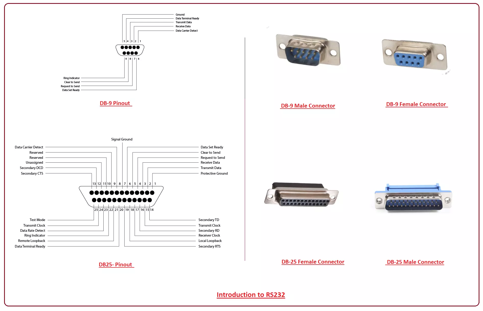
Hello Friends! Hope you are doing well. I am back to give you a daily dose of valuable information. Today, I'll discuss the detailed Introduction to RS 232 which is a standard communication protocol mainly used for serial communication between two devices. It was first introduced by the EIA (Electronic Industries Association) in 1960 to provide a pathway for connecting one device with other peripheral devices for flawless digital communication. It is true, that the inception of USB has grossly reduced the need for RS232 protocol, still, we can't brush off its significant importance in some industrial applications where Programmable Logic Controllers and Computerized Numerical Control Equipment are specifically programmed using RS 232 connectors which is nothing but an interface between DTE (Data terminal equipment) and (Data communication equipment). Don't worry about these abbreviations, I'll come to them later. In this post, I'll walk you through the basic concept of RS 232, why it is used and what are its main advantages and limitations. Let's dive in and explore the main features of the RS 232 protocol.

Introduction to RS232

RS 232, recently known as TIA 232, is a recommended standard protocol for serial data transmission between the electronic devices. It mainly works on three line signals: a transmission line, receive line and ground.
  • The transmission line is mainly used to send the data serially from one end and receive line accepts the data from the other end while the common ground is used for devices.
Initially, it was very difficult to devise the clear protocol to send the data from one end to another. This led to the inception of the RS 232 protocol, revitalizing the communication industry with the main purpose to keep both ends of the connecting device under the same roof where they can accept, understand and communicate in the same language. The RS 232 is mainly categorized into two systems: DTE and DCE. DTE is a data terminal equipment such as a computer that handles the communication with some control functions and plays the main part of the station. Similarly, DCE is a data circuit-terminal equipment that is placed on the other end of the station and understands data being communicated from the DCE equipment. The DCE system incorporates male DB connectors while the DCE system comes with female DB connectors.
  • RS232 data is bi-polar in nature, indicating an "ON or 0-state (SPACE) condition" if a voltage is around 3 to 12 V and features an "OFF" or 1-state (MARK) condition if voltage ranges from -3 to -12 V.
It is important to note that, most of the companies have reshaped the internal structure of the recent computers where they still indicate an OFF state at the zero voltage level, all the while ignoring the negative voltage. Similarly, the "ON" state is not necessarily dependent on the highest voltage level and can be achieved with much less voltage around 5V. Serial communication is mainly based on logical terms and RS232 transfers one bit at a time in the stream of ones and zeros which at the other end eventually get converted back to bits. There are eight bits in one byte.
  • The duration at which the required signal stays in the particular state is dependent on the baud rate. The communication carried out in a RS 232 protocol is measured in baud - A number of bits transferred per second i.e. 1000 baud indicate 1000 bits per second.
There are other parameters that must be set up before the data transmission: Length of the byte, Parity and magnitude of stop bits. This length of the signal can be reserved anywhere from 5 to 8 bits. The second parameter is important. Partiy mainly comes with five options
  • Even
  • Odd
  • Mark
  • Space
  • None
Even parity indicates the last data bit transmitted will be a logical 1 if it contains an even number of 0 bits. Similarly, Odd parity will be showing that the transmitted data is termed as logical 1 if it comes with an odd number of 0 bits. And MARK and SPACE parity will be representing that the last transmitted data bit will be logical 1 and 0 respectively. The last parameter is a number of stop bits and its value is set as 1 or 2. Transmission Capability RS-232 can perform transmission at data rates up to 20 Kbps with distance range capability around 50 ft. It all depends on the capacitance of the cable. The low capacity cables can transfer data up to 1000 ft while cables with high capacitance can transfer data at the lower distance.
  • As mentioned earlier many computers don't come with RS 232 port anymore, therefore we need to add USB-to RS 232 converter externally in order to make them compatible with RS 232 peripheral devices.
Although excessive use of RS 232 becomes obsolete, they are still used in low speed wired data connection and point-to-point networking equipment with short range capabilities.
Communication Process
The communication is simply based on the transmission and receive protocol and a total of 9 pins are involved in carrying out the complete transmission. The following figure shows how the data is transmitted over the terminal. Mainly the communication is laid out between DTE and DCE terminals over the mutual agreement for required data transfer. The RTS pin shows the desire to send data to another terminal. As it turns ON, it indicates the DTE terminal is ready to transfer the data. The data will be transmitted gradually over the line without any resistance if CTS pin from the other is activated and grants permission to DTE for data transfer.
  • The CD pin represents the current status of the RTS pin. If CD pin remains turned OFF, it will show the DTE terminal is not ready to send data over the channel. Similarly, turning it ON will be showing the DTW desires to send data and looking for permission from the other end.
Once the permission is granted, two other pins RD and TD come into play where former is used to receive data from DCE terminal and later is used for transferring data from DTE to DCE terminal.
  • The DTR pin must be turned ON before both terminals are ready to communicate with each other. Actually, DTR (Data Terminal Ready) will be indicating that entire arrangement from both terminals is adequate and matches with the required protocol for data transfer. It serves as a go-ahead signal for the communication.
Connector Pinout
Following figure shows the configuration of DB 25 connector. Following figure shows the pin configuration of the DB-9 connector.
  • DB-9 and DB-25 connectors offer the outstanding quality and reliability for a number of serial and parallel (IEEE 1284) applications.
Types of Serial Communication
There are two main types of serial communication. Half Duplex Full Duplex Half Duplex, as the name suggests, transfers the information in one direction only. It comes with two lines where one is a data line and other is signal ground. In this communication, the terminal is capable to send or receive data, but not at the same time. This method is an old one and is not under practice anymore. Full Duplex communication can transmit and receive data in both directions, requiring three main lines: data transmit line, data receive line and signal ground.
Applications
Before USB came into play, RS-232 ports were the part and parcel for data communication between a computer and other peripheral devices. Still, they are successful in grooving their way in many science and technology applications. Let's have a look.
  • In the absence of any network connection, RS232 ports are used to communicate in headless systems.
These ports play a vital role in establishing communication between the computer and embedded systems. Some Programmable Logic Controllers cannot be programmed without RS232 protocol.
  • Many Computerized Numerical Control Systems are equipped with RS232 port.
Apart from DB9 and DB25 ports, sometimes the two-wire interface is enough when the transmission of data is carried out in one direction only. Some GPS receiver and Digital Postal Scale work on this principle.
  • Similarly, two more lines RTS and CTS are included in a 5-wire version as per the technical needs where two-way data transmission layered with hardware flow control is required.
That's all for today. I hope you have got valuable information out of this read. If you are unsure or have any question, you can approach me in the comment section below. I'll try and help you the best way I can. You are most welcome to keep us updated with your feedback and suggestions, they help us provide you quality work as per your needs and requirements Thanks for reading the article.

Sound Sensor Library for Proteus

Update: We have created a new version of this library, which you can check here: Sound Detector Library for Proteus V2.0.
Hello friends, I hope you all are doing great. In today's tutorial, I am going to share a new Sound Sensor Library for Proteus. We are presenting this library for the first time and I would give the credit to our team, without their support it won't be possible. Proteus doesn't have this module in its library and it is used in a lot of Engineering Projects these days. This sound sensor is used to detect the sound in the surroundings and is normally known as the Sound Detector sensor. It won't recognize the sound. As we can't produce the sound in Proteus, that's why we have placed a TestPin. When this TestPin is HIGH, that means we have sound in the surroundings and if it's LOW then there's silence. Analog sound detector sensors are also available but our sensor is a digital one. So, now let's have a look at How to download & simulate this Sound Sensor Library for Proteus:
Where To Buy?
No.ComponentsDistributorLink To Buy
1Arduino UnoAmazonBuy Now

Sound Sensor Library for Proteus

  • First of all, download the Library files for the sound detector sensor by clicking the below button:
Sound Sensor Library for Proteus
  • Open this downloaded zip file, and extract below three library files:
    • SoundSensorLibraryTEP.LIB
    • SoundSensorLibraryTEP.DLL
    • SoundSensorLibraryTEP.HEX
  • Place these three files in the Library folder of your Proteus software.
Note:
  • Now restart your Proteus ISIS software and in the components section, make a search for sound sensor, as shown in the below figure:
  • As you can see in the above figure, we now have 3 sound sensors in the Proteus database.
  • So, now I am gonna place all of them in my Proteus workspace and here's how they look like:
  • They are all similar in operation, I just changed the base color as there are different versions available.
  • Now in order to make them work, we have to add the hex file.
  • Double click the sensor to open its Properties panel and in the Program File section browse to SoundSensorLibraryTEP.HEX file.
  • We have placed this hex file in the Library folder, here's the screenshot:
  • Now click OK and our sound detector sensor is ready for simulation.
  • So, let's design a simple circuit to test it out, as shown in the below figure:
  • When the TestPin will get HIGH, that means we have sound in the surroundings. In that case OUT Pin will also go HIGH.
  • In case of silence, OUT Pin will remain LOW.
  • Let's run our simulation and test it out as shown in the below figure:
  • So you can see in the above figure that LED is ON when the TestPin is HIGH and its OFF when the TestPin is LOW.
  • So that's how you can detect sound in Proteus.
  • I have also created this video which will give you a better understanding of How to download and use this Sound Sensor Proteus Library.
I hope you will like this Proteus Library. If you have any suggestions regarding this Proteus Library then ask in the comments and we will try our best to resolve them. Thanks for reading. :)

Introduction to Arduino Duemilanove

Hey Fellas! Hope you are doing well. I feel pleasure to have you on this platform. Today, I'll discuss the detailed Introduction to Arduino Duemilanove which is a Microcontroller Board, introduced by Arduino.cc and is based on ATmega168 or ATmega328. It comes with 14 pins that can be used both ways: Input or Output. Duemilanove means "2009" in Italian. Arduino boards have always been a good pick for hobbyists and students who intend to design projects that are mainly related to embedded system and automation. These boards are similar to microcontrollers, with little advantage over them as they come with some built-in peripheral features, setting you free from buying external components to employ automation in your project. If we focus on Arduino Duemilanove, it incorporates an ICSP header, a power jack, a reset button, and USB connection. A 16 MHz crystal is added on the device, aiming to produce clock pulses with regular intervals. In this post, I'll try to cover each and everything related this Arduino Board i.e. main features, pinout, pin description, software used and applications. Let's jump right in.

Introduction to Arduino Duemilanove

Arduino Duemilanove is a Microcontroller Board that is based on ATmega168 or ATmega328.
  • It comes with 14 I/O pins, out of which 6 are used as a PWM output Pins.
This board is useful where low speed and memory space is required. You can not compare it with Arduino Mega that proves to an ideal choice for high-speed applications. Still, if you aim to produce a project with simple functions, Arduino Duemilanove comes handy and stands fit for your technical requirements. It is a most recent version of the board housing USB connection and can operate at 5V with an Input voltage ranging between 6 to 20 V, however, it is advised to keep the voltage range from 7 to 12 V.
  • The Flash Memory is different depending on the microcontroller incorporated into the board: 16 KB for ATmega168 and 32 KB for ATmega 328. Out of this total flash memory, 2 KB is reserved for a bootloader. 
Similarly, SRAM featured on the device is 1 KB  while using ATmega168 and 2 KB for ATmega328. 
  • This board can be powered up both ways: connecting with a computer using USB cable or using DC adopter.
A reset button is added on the device that helps in resetting the module in case there comes a glitch in a running program and module requires instant reset that brings it back to the initial condition.
  • There is a built-in LED connected to digital pin 13, toggling between ON and OFF as you send HIGH and LOW respectively.

1. Arduino Duemilanove Features

Features of any device help you make a final decision before buying it for your project. Following table shows the main features of Arduino Duemilanove.
Microcontroller ATmega168 or ATmega328
CPU 32-Bit ARM Chip
Digital I/O Pins 14
PWM Output 6 (out of 14 I/O pins)
Analog Input 6
Flash Memory (Program Memory) 16 KB for ATmega168 and 32 KB for ATmega 328
SRAM 1 KB  for ATmega168 and 2 KB for ATmega328
EEPROM 512 bytes for ATmega168 and 1 KB for ATmega328
Input Voltage 7-12 V
Operating Voltage 5 V
Oscillator up to 16 MHz
Software Used Arduino IDE
Reset Button Yes
ICSP Header Yes
USB Port 1
UART (Serial Communication) Yes
SPI Protocol Yes
I2C Protocol Yes
DC Current per I/O Pin 40 mA
DC Current for 3.3V Pin 50 mA
  • Three communication protocols available on the board will help in connecting the module with external devices.
  • There is a slight difference in the memory used in the module based on the controller incorporated on the board. Before you intend to buy the module, make sure your technical requirements are quite in line with the memory space available on the board.

2. Arduino Duemilanove Pinout

Following figure shows the pinout of this Arduino Board.
  • There are total 28 physical pins on the board and six pins are available on the ICSP header. Four female headers are available covering all physical pins for the connection with the external devices.

3. Arduino Duemilanove Pin Configuration

In the previous section, you have got a brief overview of the Arduino module pinout. Now, we will highlight the major functions associated with each pin, so you can anticipate what each pin is capable to perform, helping you use the relevant pin for your project.
Digital I/O Pins
There are 14 digital I/O pins on the board that can be used as an input or output based on requirement. If you are working with sensors, these pins can be made as an input to accept the digital input from the sensor, similarly, if you are aiming to control the motor, these pins are used as an output for writing the required command to control the motors.
Analog Pins
There are 6 analog pins available on the board. These pins can accept any value, unlike digital signals that are designed to deal with only two values: HIGH and LOW. The following figure shows the location of analog pins on the board.
PWM Pins
There are six PWM pins (out of 14 digital I/O pins) incorporated on the board. PWM (pulse width modulation) is a process for getting analog results with digital means. These pins appear on the right side of the board as you place the board with power jack pointing upward.  Following figure shows the placement of these pins on the board.
ICSP Header
ICSP (In-Circuit Serial Programming) header is added that help to connect the board with computer and upload a sketch in case USB port is not available.  This feature is mainly used to program Arduino with another Arduino.
Power Source Pins
There are four main voltage sources i.e. Vin, 5V, 3.3V, AREF, available on the board. The Vin is the input voltage that ranges between +7 to +12 V and comes from the external power source. The board operates at 5V while 3.3V is the operating voltage of each pin. There are four ground pins on the board where one is reserved for AREF and another for ICSP header while remaining two are available for the board. The AREF is an Analogue reference voltage, used for analog pins. The following figure shows the power source pins.
Communication Protocols

Common communication protocols like SPI, UART and I2C are available on the board. It is important to note that SPI communication is available on both: digital I/O pins and ICSP header pins.

Serial Peripheral Interface (SPI) is commonly used to send data between microcontrollers and small peripherals such as sensors, shift registers, and SD cards. It comes with separate clock and data lines, layered with a select line to choose the device for communication.

Similarly, I2C is a two-wire interface that contains two main lines known as SDA and SCL where former is s serial data line that carries the data and later is serial clock line that is used to synchronize all data transfers over the I2C bus.

4. Programming and Communication

Almost all modules falling under the Arduino family are programmed using  Arduino IDE - Official software introduced by Arduino.cc for programming Arduino Modules. This software is compatible with common operating systems like Windows, Linux or MAC.
  • You need to take care before installing the software version for your system i.e. if you want to download Arduino IDE App version, you must have Windows 10 installed in your system as app version is not compatible with Windows 7 or 8.1.
The software is very easy to use and is readily available on the Arduino Website. It is an open source software i.e. you can use it freely and modify your Arduino Board as per your requirements. Some basic codes are already available on the software, you just need to connect the board with the computer and upload the required program and start playing with your board right away.
  • Arduino never fails to keep your budget at the bare minimum as no external burner is required to burn the code inside the module due to Module's built-in bootloader, however, if you aim to insert a new controller on the module, you have to install the bootloader again using IDE software.
Arduino IDE comes with a number of options to select the required Arduino Board, simply go to Tools Menu and click Board section and select the board you are working on.
  • Software comes with a compilation option that allows you to see the code compilation on the bottom of the screen as you upload the code, generating a code hex file which then is transferred to the board.
The physical pin 0 and 1 are used for UART communication and FTDI  chip on the board sets a pathway to bridge the serial communication between FTDI drivers and USB. As you send the data using FTDI chip and USB connection, the RX and TX will flash, indicating information is being transferred to the computer.

5. Arduino Duemilanove Projects and Applications

Arduino Duemilanove comes with a wide range of applications and features a number of peripheral features. Following are some major applications it can be used for:
  • Student Projects
  • Industrial Automation
  • Health and Security Systems
  • Embedded Systems
  • Motor and Sensor Control
That’s all for today. I hope I have given you everything you needed to know about Arduino Duemilanove. However, if you are unsure or have any question you can comment in the section below. I’d love to help you in any way I can. You are most welcome to keep us updated with your valuable feedback and suggestions, they help us provide you quality work as per your needs and requirements. Thanks for reading the article.

Introduction to CD4047

Hi Guys! Hope you are doing well. In this platform, we always strive to keep updated with valuable information related to engineering and technology. Today, I'll discuss the detailed Introduction to CD4047. It is a CMOS Low Power monostable/astable multivibrator mainly used for converting DC current signal to AC signal. This inverter proves to be very handy in some countries where load-shedding creates a significant problem as it comes with an ability to store electrical energy and discharge it in the absence of main electrical power. In this tutorial, I'll cover the entire details on this inverter, its main features, working, and applications. Let's dive in and explore everything you need to know about this inverter.

Introduction to CD4047

CD4047 is a CMOS Low Power monostable/astable multivibrator mainly used for converting DC current signal to AC signal. It comes with a high voltage rating around 20-V.
  • CD4047 is a 14 pin IC that operates on a logic techniques with an ability to allow negative or positive edge-triggered monostable multivibrator action layered with retriggering and external counting options.
Accurate and complemented buffered output with low power consumption make this IC an ideal choice for Frequency Division and Time Delay applications. The internal power-on reset circuit is added on the IC and fast recovery time makes it an independent from the pulse width.
  • There is a sheer difference involved when IC works in monostable and astable mode. In monostable mode, the inverter needs a trigger signal for generating the output pulse, but an astable multivibrator doesn't require trigger signal for every output pulse. More often than not, an astable multivibrator can be called as an oscillator.
CD4047 Features
No matter what type of operation this IC undergoes, an external resistor is permanently connected between RC-Common and R timing terminals and an external capacitor is connected between RC-Common and C timing terminals. The following figure shows the main features of this IC.
Features
Low Power Consumption Noise Resistance Generate both Monostable and Astable operation Symmetrical buffered output characteristics One resistor and one capacitor is used externally
Monostable Features
Output pulse width doesn't dependent on trigger pulse duration Pulse width expansion with retrigger option The positive and negative edge trigger option is available
Astable Features
Creates 50% duty cycle Free running operating modes Oscillator output Impressive frequency stability
CD4047 Pinout
Following figure shows the pinout diagram of CD4047.
  • There are 14 pins available on the IC where Vss is a ground pin and Vdd is a voltage supply pin. There are six inputs including trigger', trigger, astable, astable', external reset and retrigger. While buffer outputs include three outputs mentioned as Q, Q', and Oscillator.
Both astable and astable' take part for triggering the operation by keeping high level on the former and low level on the later.
  • The IC behaves as a gatable multivibrator if complement pulses on the astable' and true pulses are applied on the astable pins.
The CD4047 will be only triggering in a monostable state when a positive edge appears on the +trigger with -trigger keeping low.
CD4047 Pin Description
As mentioned earlier there are 14 pins on the IC interface with every pin is used with a specific purpose. Folloiwng table shows the pin description of each pin.
Pin# Pin Name Pin Description
1 C Connected to an external capacitor
2 R Connected to an external resistor
3 R-C Common Common pin for establishing a connection with resistor and capacitor
4 Astable' Must be kept low when used in astable mode
5 Astable Must be kept high when used in astable mode
6 -Trigger High to Low transition will be given to this pin when used in Monostable mode
7 Vss Ground Pin
8 +Trigger Low to high transition will be given to this pin when used in Monostable mode
9 EXT Reset External reset triggers when a high pulse is provided to this pin, resetting the output Q to low and Q’ to high
10 Q Generates high output
11 Q' It is an inverse output of pin 10, producing a low output
12 Retrigger This pin is used in Monostable mode for simultaneously retriggering +trigger and –trigger pin
13 Osc Out Generate oscillated output
14 Vdd Voltage supply pin
CD4047 Working in Monostable and Astable Mode
CD4047 is a low power inverter that comes with an ability to operate in both states: astable or monostable mode. In astable mode, it operates by charging a capacitor using a valuable resistor that is mainly used to adjust the output frequency near 50Hz. Monostable Mode In Monostable Mode, an external resistor must be connected between Pin 1 & 3 of the IC that helps in determining the output pulse width. We will be using +trigger and –trigger Pin in this mode. Both pins will generate the Monostable output when we provide High to Low transition at –trigger Pin and Low to High transition at +trigger Pin. The following formula is used to determine the frequency at Pin 10 & 11

f = 1 / 8.8 x R*C

Astable mode As mentioned earlier in astable mode, the inverter needs a trigger signal for generating the output pulse. The output frequency is determined when a single capacitor is connected between PIN 2 and 3. The IC will be operating is an Astable mode when we apply  HIGH on Pin 5 and LOW on Pin 4, generating the output toggling between HIGH and LOW. The oscillated output frequency on Pin 13 can be determined using the following formula

F = 1 / 4.4 x R*C

Similarly, the formula to find the time it takes to generate pulse will be given as:

t = 2.48 x R*C

Applications
This inverter comes with a wide range of applications that are mainly related to DC to AC conversion. Following are the main applications it can be used for.
  • Frequency division
  • Frequency multiplication
  • Timing delay applications
  • Timing circuits
  • Frequency discriminators
That’s all for today. I hope this article has helped you got a complete overview of CD4047 and the main functions associated with it. If you are unsure or have any question, you can ask me in the comment section below. I’d love to assist you in any way I can. Feel free to give your feedback and suggestions that help us provide you quality work based on your needs and requirements. Thanks for reading the article.

Introduction to Arduino Leonardo

Hi Guys! Hope you are getting along with life pretty well. I always strive to keep you updated with most valuable information related to engineering and technology. Today, I'll discuss the detailed Introduction to Arduino Leonardo. It is a microcontroller board based on the ATmega32U4 and comes with 23 digital input/output pins. It is developed by Arduino.cc, aiming to provide easy to use interface with the ability to perform a number of functions on a single chip. It incorporates everything required to drive the automation in the relevant project. Simply connect this device with the USB cable or power it up using DC adapter and start playing with it In this post, I'll try to cover each and everything related to Arduino Leonardo, so you don't need to wrestle your mind browsing the whole internet and find all the information in one place. Let's dive right in and get down to the nitty-gritty of this tiny module.

Introduction to Arduino Leonardo

  • Arduino Leonardo is a microcontroller board developed by Arduino.cc. It is based on the ATmega32U4 and comes with 23 digital input/output pins that are enough to connect with external devices and turn your innovation into reality.
  • The Microcontroller on the board incorporates a built-in USB communication, setting you free from the use of a secondary processor. The USB communication helps Leonardo disguise the mouse or keyboard when it is connected to a computer.
  • The module supports the crystal oscillator with the frequency up to 16 MHz that is enough to generate clock pulses with decent pace required for the synchronization of all the internal operations.
In-circuit programming header is added in the device that gives you the flexibility to tweak the already written code after its installation in the relevant project.
  • This board supports common communication protocol like UART, SPI, and I2C. The UART is a serial communication protocol mainly used for transferring and receiving serial data using two pins called TX and RX.
While I2C is a two-wire interface that involves two main lines known as SDA and SCL where former is s serial data line that carries the data and later is serial clock line that is used to synchronize all data transfers over the I2C bus.
  • Serial Peripheral Interface (SPI) is a third communication protocol added on the board that is commonly used to send data between microcontrollers and small peripherals such as sensors, shift registers, and SD cards using separate clock and data lines, layered with a select line to pick the device for communication.

1. Arduino Leonardo Features

If you aim to work on your desired project, you must know the common features this device holds in order to avoid any hassle in future, getting you a clear idea if the ratings of the device are quite in line and stand fit for your project. Following table shows the main features of the Arduino Leonardo.
Microcontroller ATmega32U4
CPU 8-Bit
Digital I/O Pins 23
PWM Output 7
Analog Input 12
Flash Memory (Program Memory) 32 KB (Out of which 4 KB is used by bootloader)
SRAM 2.5 KB
EEPROM 1 KB
Input Voltage 7-12 V
Operating Voltage 5 V
Oscillator up to 16 MHz
Software Used Arduino Software (IDE)
Reset Button Yes
ICSP Header Yes
USB Port 1
UART (Serial Communication) Yes

2. Arduino Leonardo Pinout

Following figure shows the pinout of Arduino Leonardo.
  • USB jack, Power Jack and Reset button are quite in line with each other and are surfaced on one side of the board. Nonetheless, all components and pins on the board are designed in a regular pattern, giving a compact and symmetrical interface.

3. Arduino Leonardo Pin Description

You have got a clear idea about some of the basic functions of this Arduino Module. In this section, we will break down pinout of the board with different images and describe them in terms of pin description of the board. Let's get started.
Analog Pins
There are 12 analog pins added on the board. As per the nature of these pins, they can utilize any number of values, unlike digital signals that are designed to deal with only two values: HIGH and LOW. The following figure shows the placement of these analog pins on the board.
PWM Output
There are seven PWM pins available on the board. If you place the board with power jack pointing upward, these pins appear on the right side of the board. PWM is a process for getting analog results with digital means. You can see these pins in the figure below.
Communication Protocols

Three communication protocols including SPI, UART and I2C are incorporated on the board. You can see them on the figure below. It is important to note that SPI communication is not available on the digital I/O pins like other boards instead, it houses in the ICSP header as shown in the figure below.

Power Source
Difference power sources are available for a variety of purpose. Mainly, the board operates at 5V while 3.3V is the operating voltage of each pin. The Vin is the input voltage that ranges between +7 to +12 V. This voltage comes from the external power source. There are two ground pins on the board. The AREF is an Analogue reference voltage, mainly used for analog pins. The IOREF is useful for powering and developing a compatibility between this board and Arduino Shields. As the shield is connected with this pin, it (shield) wears the I/O voltage provided by the Board. The Shield using IOREF pin will be compatible with both 3V3 and 5V. You can see the power source in the figure below.
ICSP Header
ICPS stands for In-Circuit Serial Programming – A feature used for programming Arduino with another Arduino. ICSP header is added that helps in connecting the board with a computer for uploading a sketch in case USB port is not available.

4. Programming

  • Arduino.cc has introduced its own official software, called Arduino IDE, for programming the Arduino module. This software supports common operating systems like Windows, Linux or MAC. Before you download this software, make sure the required software version is compatible with your system i.e. if you aim to download App version, you must have Windows 10 installed in your system as app version is not compatible with Windows 7 or 8.1.
You are ready to use the software as you install it. Some simple LED programs are already available on the software, giving you the flexibility to start working on the board in due course.
  • No external burner is required to burn the code inside the module as it comes with a built-in bootloader. Having said that, if you intend to insert a new controller on the module, you need to install the bootloader again using IDE software.
The Serial Monitor is added in Arduino Software, that helps you see the code working in real time as you verify and upload the code.
  • Arduino IDE comes with a compilation option that allows you to see the code compilation on the bottom of the screen as you upload the code. It generates hex file of the code which then is transferred into the board.

5. Difference between Arduino Leonardo and Arduino Uno

There is a slight difference between these two boards in terms of controller used, number of digital pins, PWM pins, and the pins reserved for SPI communication.
  • Arduino Uno incorporates ATmega328 while Arduino Leonardo comes with ATmega32U4.
Similarly, Uno has 20 digital I/O pins, out of them 6 are analog input pins and Leo has 23 digital I/O pins, out of which 12 are analog input pins.
  • There are 7 PWM output pins available on the Leonardo and 6 are added on the Uno board.
Uno comes with SPI protocol on the digital I/O pins while Leonardo contains SPI communication on the ICSP header pins.

6. Arduino Leonardo Projects and Applications

You can not write off the importance of Arduino Modules if you are working on a project that comes with a remote connection with automation. Arduino Leonardo comes with a wide range of applications and incorporates a number of peripherals, setting you free from the hassle of spending too much for buying external components. Following are some major applications Arduino can be used for:
  • Industrial Automation
  • Health and Security Systems
  • Creating wireless keyboard
  • Automatic Pill Dispenser
  • Embedded Systems
  • Student Projects
  • USB Trackpad
  • Water Level Meter
That’s all for today. I hope you have got a lot of information regarding Arduino Leonardo. However, if you are unsure or have any question you can approach me in the comment section below. I’d love to help you the best way I can. You are most welcome to keep us updated with your valuable feedback and suggestions, they help us provide you quality work that resonates with your needs and requirements. Thanks for reading the article.

Introduction to HC-SR04 (Ultrasonic Sensor)

Hi Friends! I hope you are doing well. Welcome you onboard. Today, I'll discuss the basic Introduction to HC-SR04 Ultrasonic Sensor. It is an ultrasonic sensor, also known as an ultrasonic transducer that is based on a transmitter and receiver and mainly used to determine the distance from the target object. The amount of time it takes to send and receive waves will determine how far the object is placed from the sensor. It mainly depends on the sound waves working on “non-contact” technology. The required distance of the target object is measured without any damage, giving you accurate and precise details. This sensor comes with a range between 2cm to 400cm and is used in a wide range of applications including speed and direction measurement, wireless charging, humidifiers, medical ultrasonography, sonar, burglar alarms, and non-destructive testing. In this post, I'll try to cover basic details related to HC-SR04, so you get an idea what is this about and how it can be used in the major applications as per your needs and requirements. Let's jump right in and get down to the details on this ultrasonic sensor.

Introduction to HC-SR04 ( Ultrasonic Sensor )

  • HC-SR04 is an ultrasonic sensor mainly used to determine the distance of the target object.
  • It measures accurate distance using a non-contact technology - A technology that involves no physical contact between sensor and object.
  • Transmitter and receiver are two main parts of the sensor where former converts an electrical signal to ultrasonic waves while later converts that ultrasonic signals back to electrical signals.
  • You can download HCSR04 Datasheet by clicking below button:
Download HC-SR04 Datasheet
  • These ultrasonic waves are nothing but sound signals that can be measured and displayed at the receiving end.
  • Following table shows the main features of this ultrasonic sensor.
 
Parameter Value
Main Parts Transmitter & Receiver
Technology Used Non-Contact Technology
Operating Voltage 5 V
Operating Frequency 4 MHz
Detection Range 2cm to 400cm
Measuring Angle 30º
Resolution 3mm
Operating Current <15mA
Sensor Dimensions 45mm x 20mm x 15mm
 
  • It gives precise measurement details and comes with accuracy (resolution) around 3mm, terming there might be a slight difference in the calculated distance from the object and the actual distance.
HC-SR04 Pinout & Description
  • HC-SR04 contain 4 pins in total.
  • Following table shows the HC-SR04 Pinout  & Description:
 
No. Pin Name Pin Description
1 VCC The power supply pin of the sensor that mainly operates at 5V DC.
2 Trig Pin It plays a vital role to initialize measurement for sending ultrasonic waves. It should be kept high for 10us for triggering the measurement.
3 Echo Pin This pin remains high for short period based on the time taken by the ultrasonic waves to bounce back to the receiving end.
4 Ground This pin is connected to ground.
 
  • I have labelled these HC-SR04 Pinout in below figure for better visualization:
How does it work?
The HC-SR04 Ultrasonic (US) sensor is an ultrasonic transducer that comes with 4 pin interface named as Vcc, Trigger, Echo, and Ground. It is very useful for accurate distance measurement of the target object and mainly works on the sound waves. As we connect the module to 5V and initialize the input pin, it starts transmitting the sound waves which then travel through the air and hit the required object. These waves hit and bounce back from the object and then collected by the receiver of the module. Distance is directly proportional to the time these waves require to come back at the receiving end. The more the time taken, more the distance will be. The waves will be generating if the Trig pin is kept High for 10 µs. These waves will travel at the speed of sound, creating 8 cycle sonic burst that will be collected in the Echo pin. The echo pin remains turned on for the time these waves take to travel and bounce back to the receiving end. This sensor is mainly incorporated with Arduino to measure the required distance. Following formula is used to calculate the distance of the object.

S = (V x t)/2

Where S is the required distance, V is the speed of sound and t is the time sound waves take to come back after hitting the object. We need to divide the value by 2 because time will be double as the waves travel and bounce back from the initial point. Dividing it by 2 will give the actual distance of the target object.
Using HC-SR04 with Arduino Module
In order to get the precise distance measurement, HC-SR04 is mostly used in combination with different Arduino Modules like Arduino Uno and Arduino Mega. You can connect Arduino with this sensor in the following way.
  • First, you need to power up the sensor using 5V DC regulated input to the sensor. Connect the ground pin with the ground of the voltage source. You can also power the sensor module using the Arduino 5V pins as the current drawn by the sensor is less than 15mA, won't be affecting the current ratings of the Arduino Module.
After setting up the initial arrangement, connect both Trig and Echo pins to the I/O pins of the Arduino Board. As mentioned earlier, in order to initialize the measurement process, the Trig pin must be kept high for 10us in the start. The sensor module will start generating sound waves with the frequency around 40,000 Hz per second from the transmitter.
  • As the waves bounce back, consequently, the Echo pin will turn on until the sounds waves are received by the receiver. This time will be calculated using Arduino Module.
This tutorial that will help you How to Interface Ultrasonic Sensor with Arduino Module You can also Interface Multiple Ultrasonic Sensors with Arduino Module
Applications
HC-SR04 comes with a wide range of applications mainly targeting distance and direction measurements. Following are the major applications it can be used for.
  • Speed and direction measurement
  • Wireless charging
  • Humidifiers
  • Medical ultrasonography
  • Burglar alarms
  • Embedded system
  • Depth measurement
  • Non-destructive testing
That's all for today. I hope I have given you everything you needed to know about this sensor. If you are unsure or have any question, you can approach me in the comment section below. I'd love to help you the best way I can. Feel free to keep us updated with your valuable feedback and suggestion, they help us stay above the curve and give you quality content as per your demands. Thanks for reading the article.

Introduction to LED (Light Emitting Diode)

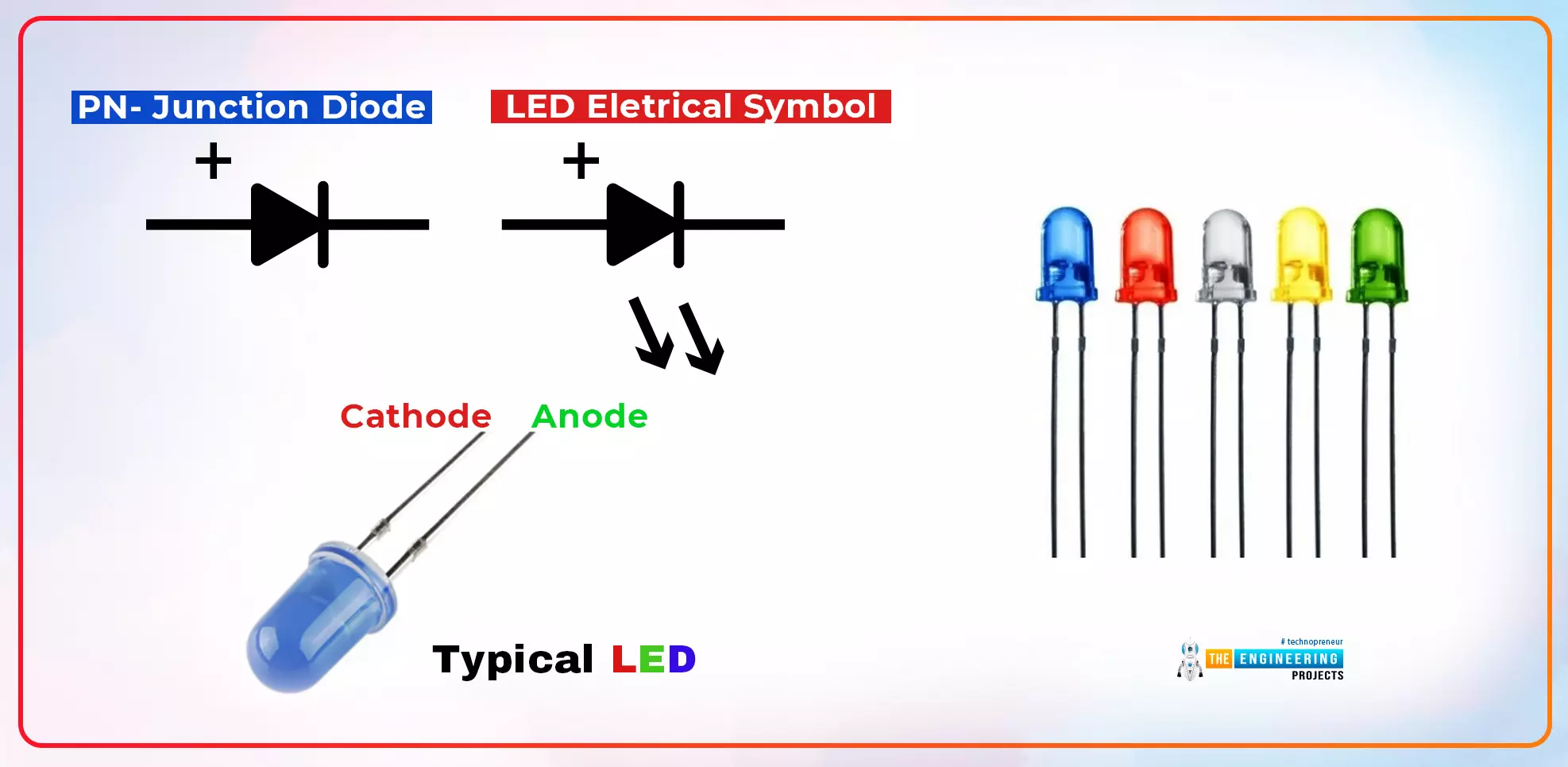
Hi Friends! Hope you are doing well. I always feel pleasure to keep you updated with information related to engineering and technology. Today, I'll unlock the detailed Introduction to LED. The LED stands for Light-emitting diode. LED is a PN-junction diode mainly used as the source of light.

The LED has a leg over common orthodox incandescent light in terms of efficiency, low consumption power, compact size, longer range and an ability to retain the quality for a longer period of time. It comes with a wide variety of applications ranging from automotive headlamps, camera flashes, aviation lighting, traffic signal, and medical devices.

In this post, I'll try to cover each and everything related to LED, so you don't need to wrestle your mind browsing the whole internet and find all the information in one place. Let's dive in and get down to the detail of this little semiconductor component.

Introduction to LED (Light Emitting Diode)

LED is a PN-junction diode that is mainly used as a replacement for incandescent lights. It is based on the electroluminescence effect - A process where a diode converts electric current to light when electrons change their state inside the LED semiconductors.

The PN-junction is nothing but a combination of both N-type and P-type semiconductor materials. The material forming the junction diode is not identical to other mainstream didoes, as it comes with a transparent package, allowing the infrared and visible light to pass through the junction.

  • The LED contains two terminals known as anode and cathode. The former contains a positive charge on it and comes with the longer lead as compared to others, and later contains a negative charge on it.

LED will be working under one condition: the anode terminal should be put at a higher potential than the cathode terminal as current flows from anode to cathode (positive to negative). LED won't conduct if the respective terminals are connected in reverse order.

  • LEDs, also known as infrared-emitting diodes, are very helpful in a wide range of applications. The experts were always in a need of creating an alternative to regular bulbs that turned out to be expensive and less efficient. The first experiment on electroluminescence was conducted in 1907, followed by a number of experiments later on that resulted in the development of visible light.

The brightness of every LED depends on the current drawn by it - the most the current drawn the more brightness will be.

There is a threshold set for the current every LED can withstand, increasing it from the rated value will burn the LED.

In the start, LEDs came with Infrared low-intensity light that grooved their way in the remote control applications, mainly targeting consumer electronics. In that time, the Red light was mainly used in the LED, however, in 2002 the experts succeeded in adding the White light to the LED semiconductor.

  • The LED underwent through a number of tests and experiments and evolved over the years, however, recent LEDs come with different wavelengths ranging from ultraviolet, visible, to infrared wavelengths, producing light with high brightness.

The efficiency by which the LED converts electricity into the light is remarkable which makes it an ideal choice in the computer chip technology, adding an extra layer of both efficiency and robustness.

Note: The LED is not symmetrical in nature, allowing current to flow in one direction only.

LED Working Principle

LED is mainly comprised of four parts known as die, substrate, phosphor, and lens. The die is a semiconductor material containing gallium nitride (GaN) that emits blue light when the electric current passes through it. In order to provide easy integration of LED, one or two dies are used in combination with the substrate, generating enough power to light up the LED.

  • White light is mainly preferred over blue one in general lighting applications where the desired color is produced using phosphor.

The blue light, emitting from the die, will generate white light once it hits phosphor particles.

  • It is important to note that the phosphor can be applied to die material both ways: directly or layered with the lens material that either extracts or directs the light and mainly comes with silicon or glass.

The LED, more often than not, generates monochromatic light ranging from red to blue and violet.

  • Traditional LEDs are formed using inorganic semiconductor materials including aluminum, gallium, silicon, indium, and zinc that produce a different color based on the type of material used: aluminum gallium phosphide produces green color, while aluminum gallium nitride and aluminum gallium arsenide produce ultraviolet and red light respectively.
The LEDs are also rated with respect to the voltage required to turn them on where red LEDs come with a maximum voltage rating of around 2.2V, while blue LEDs and white LEDs come with a voltage rating of 3.4V and 3.6V respectively.

Temperature Limitations

The LED never fails to satisfy the power consumption needs of a regular user, however, the use of this tiny component in a high temperature and pressure environment can make it highly vulnerable. Taking this point into consideration, some LEDs incorporate a heat sink on their interface, which prevents them from overheating and makes them an appropriate pick in conditions where high temperature is a major concern.

  • A very high temperature can make the heat sink stopped working and put your LED in a total stall. Before you aim to use LED for your relevant project, make sure the temperature ratings match and resonate with the LED you are using.

Types of LEDs

LEDs are available in a variety of types. Some are preferred over others based on the nature of their applications. Following are some main types of LEDs.

High Power LEDs

LEDs are known as High Power LEDs if their power rating is greater than or equal to 1 Watt. They are mainly used for generating the maximum brightness. The input power required for these LEDs is very high, making them prone to heat dissipation.

Heat sinks are required to keep these LEDs cool and impede them from burning. Flashlights, spotlights, and automobile headlamps are some major applications of High Power LEDs.

RGB LEDs

It is widely used in many computer applications and comes with the ability to generate three lights, as the name suggests, red, blue and green. The color of these lights is controlled by using PWM (pulse width modulation). Both the duty cycle of PWM and the frequency used for generating the signal per second, prove to be handy for controlling all three colors.

SMD LED

SMD LED stands for Surface Mount Device LED. It comes in a special package with the ability to be mounted on the PCB surface. It can be easily categorized based on the physical dimensions. It works both ways: separately or in combination with a compatible device.

Thru-Hole LED

Thru-hole LED comes with two terminals leads that are embedded into the holes of the printed circuit board. They are available in a variety of different packages and shapes. Most common colors they come with are white, red, blue and green.

Why LED?

It is arguably correct, LED consumes 75% less power than normal incandescent without failing to produce the brightness with equal intensity.

Yes, buying it may make your budget bleed in the start as it features more costly as compared to regular halogen light, but it proves to be economical in the long run due to its high quality, longer life span and less power consumption.

LED Applications

The compact size of the LED makes it stand to fit in hard-to-reach places including ceiling lighting, cove lighting, tray, and cabinet lighting.

  • Thanks to the robust nature of LEDs - without them, Landscape lighting would never be so easy and created flawlessly as it has been right now. The LEDs play a vital role in generating and optimizing the light beam angle at the desired distance and their ability to disguise any shape as per the nature of the environment they are incorporating in, helps them serve a real purpose, adding curated light layered with beauty using a single source.

Some of the digital clocks are developed using the LED interface. And the 7-segment LED display is a widely used student project that incorporates the array of LEDs in an organized manner.

  • They are profoundly used in automotive industries, LCD panels, fiber optics data transmission, and remote control devices. While pointing out the sheer advantages of LEDs, we can't write off their value in advertising. They are mainly used to captivate the visitors - when placed in the advertising banner and tree decorated with a number of infrared lights will help in getting the instant attention of the customers.

That’s all for today. I have given you everything you needed to know about LED. If you are unsure or have any questions, you can ask me in the comment section below. I’d love to help you the best way I can. You are most welcome to share your valuable feedback and suggestion, they help us provide you with quality work as per your needs and requirements so you keep coming back for what we have to offer. Thanks for reading the article.

Syed Zain Nasir

I am Syed Zain Nasir, the founder of <a href=https://www.TheEngineeringProjects.com/>The Engineering Projects</a> (TEP). I am a programmer since 2009 before that I just search things, make small projects and now I am sharing my knowledge through this platform.I also work as a freelancer and did many projects related to programming and electrical circuitry. <a href=https://plus.google.com/+SyedZainNasir/>My Google Profile+</a>

Share
Published by
Syed Zain Nasir