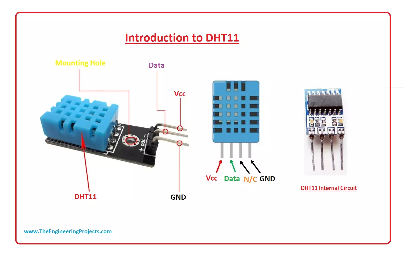
Hello Friends, I hope you all are fine and will be doing well in your life. In today's tutorial, I am going to give you a detailed Introduction to DHT11. It is an embedded sensor used to measure temperature & humidity in the surroundings and gives calibrated digital output. It can measure temperature in the range of 0°C to 50°C with ±2°C accuracy. Its humidity range is from 20% to 80% with ±5% accuracy. It is a small, low cost and easy-to-interface embedded sensor.
In this tutorial, I will explain its working, pinout, protocol and interfacing with other microcontrollers in detail.
Here are a few important features of DHT11, given in the below table:
DHT11 Features & Specs
No.
Parameter
Value
1
Measures
Humidity & Temperature
2
Sensor ...
Hello friends, I hope you are all fine and will be doing something interesting in your life. in today's post, I am going to discuss Introduction to DHT22. It is a temperature and humidity measure sensing device. It is easily used but it needs a specific time for an operation. Its temperature measuring range is from -40 to +125 degrees Celsius with +-0.5 accuracy. This sensor measures moisture content and temperature. This sensor is easily connected to other microcontrollers.
DHT22 plays an important role in our environment in measuring temperature and moisture. It is a low cost easy-to-use small sensor. This sensor is used at different weather stations to measure temperature and ratio of moisture in the air, in this way, they tell about tem ...
Hello friends, I hope you all are doing great. In today's tutorial, we are gonna have a look at detailed Introduction to HC-06. HC-06 is a class 2 slave Bluetooth module designed for serial communication. Once it is paired to a master Bluetooth device such as PC, smartphones, and tablet, its operations become easier to the user. It sends and receives data in a bidirectional manner.
HC-06 is used in different devices which works on Bluetooth for sending and receiving data. In today's post, we will have look at its pinout, working, circuit diagram, protocol, etc. I will also share some links of projects where I have interfaced it with Arduino and some other microcontroller. Friends if you have any questions please ask in comments I will try my bes ...
Hello Friends, I hope you all are fine and having fun in your lives. In today's post, we are gonna have a look at detailed Introduction to NRF24L01. NRF24L01 is basically a wireless transceiver, which is used to send and receive data by using radio waves. It is a single chip transceiver module. It uses SPI protocol for transmitting data. Its data transmission speed is up to 2Mbps.
NRF24L01 is normally used in industrial devices and projects for data transmission. It is mostly used in computer, toys, remote control, games, and other electronic devices. In today's tutorial, I will discuss its working, protocol, pinout, and features. I will also share some links of its interfacing with Arduino and some other microcontrollers. if you have any questions regarding it, please ask in comment bo ...
Hello friends, I hope you are all fine and will be doing something special in your life. In today's post, we are gonna have a look at a detailed Introduction to MPU6050. MPU6050 is a sensor for motion processing devices. It is the world's first six-dimension motion tracking device. It was designed for low-cost and high-performance smartphones, tablets and wearable sensors. It is capable of processing nine-axis algorithms, it captures motion in X, Y and Z axis at the same time.
MPU6050 is used in different industrial projects and electronic devices to control and detect the 3-D motion of different objects. In today's post, we will have a look at its working, pinout, protocol, it's interfacing with Arduino, features, applications, etc. I will also share some links of projects wh ...
Hello friends, I hope you are all fine and doing great. In today's tutorial, we will have a look at a detailed Introduction to MFRC522. MFRC522 is an RFID Embedded module used to read and write RFID cards and operates at 13.56MHz contactless communication. It is a less costly, low-voltage, and small-sized non-contact card chip. It is the best choice for intelligent instruments and portable handheld devices. It communicates with microcontrollers over SPI Protocol.
MFRC522 is used in different engineering projects, mostly for security purposes in offices, banks, plazas, etc. You must have seen in English Movies that a person just shows his ID card to the machine and its whole profile data pops up on the computer and if he is authorized then the front door automatically ...
Hello friends, I hope you all are doing great. In today's tutorial, I am going to share a new PC817 Library for Proteus. PC817 is an optocoupler / optoisolator, which is used for electrical isolation between components or modules. It's normally used after Microcontroller Pins so that back emf doesn't burn them. You should also have a look at Introduction to PC817, I have shared its complete details there.
PC817 is used a lot in Embedded projects but is not available in Proteus, so our team has designed it for the first time. Using this Library, now you can easily simulate this optocoupler in your Proteus simulations. So, let's get started with How to download & install PC817 Library for Proteus:
PC817 Library for Proteus
First of all, downl ...
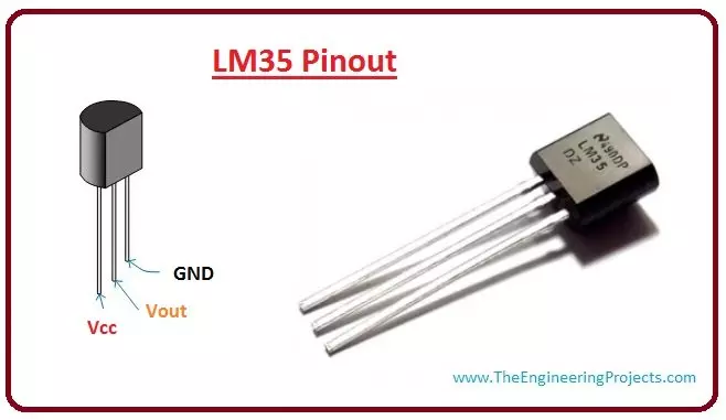
Hello friends, I hope you all are doing great. In today's tutorial, we are gonna have a look at a detailed Introduction to LM35. LM35 is a type of commonly used temperature sensor, that can be used to measure temperature with an electrical output compared to the temperature in (°C). In can measure temperature in a better way than a thermistor.
LM35 is used in industries and commercial buildings where high accuracy of temperature measuring is needed. I will give you a detailed overview of this temperature sensor in today’s post where we will have a look its pinout, working, protocol, etc. I will also share some links of projects where I have interfaced it with Arduino or other microcontrollers. If you have any questions please ask in the comments, I will resolve your queries and will gu ...
Hello friends, I hope you all are doing great. In today's tutorial, we are gonna have a look at a detailed Introduction to HC-SR501. HC-SR501 is a motion detector sensor, that uses infrared waves for the detection of an object. It is an automatic control device, and also has large sensitivity and high reliability. It is used in auto-sensing control devices, where we need to perform motion detection.
HC-SR501 is used in industrial projects and buildings for security purposes. In today's post, we will have a look at its pinout, working, protocol, circuit diagram, etc. I will also share some links to projects where I have interfaced it with Arduino and some other microcontrollers. Friends if you have any questions please ask in the comments I will try my best to solve your problems and I w ...
Hello friends, I hope you all are doing great. In today's tutorial, we are gonna have a look at a detailed Introduction to DS18B20. DS18B20 is a temperature sensor that can measure temperature from -55oC to +125oC with an accuracy of +- 5%. It follows 1 wire protocol which has revolutionized the digital world. Because of its 1 wire protocol, you can control multiple sensors from a single pin of Microcontroller.
DS18B20 is normally used in industrial projects where high accuracy is necessary. I will give you a detailed overview of this temperature sensor in today's post where we will have a look at its Pinout, working, protocol, etc. I will also share some links to projects where I have interfaced it with Arduino or other microcontrollers. If you have any questions, please ask in comment ...