Hello readers, hope you all are doing great. Today, we will discuss interrupts and timers in ESP32 and how to handle internal as well as external interrupts. So, we will discuss What is interrupt, Polling, ESP32 interrupt, Software interrupts, Hardware Interrupts, IRS (Interrupt Service routine), Steps to execute an interrupt or how is an interrupt handled in the microcontroller, Code description for ESP32 interrupts with Arduino IDE, Code description for hardware interrupts, Why is it preferred to use timer to add delay instead of using delay() function. So, let's get started:
What is Interrupt?
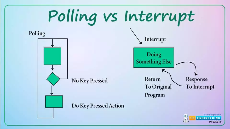
Interrupts are used when a micro-controller needs to continuously monitor for an event while the same micro-controller is executing a particular task ...
Hello readers, hope you all are doing great. This is our 3rd tutorial in the ESP32 programming series. In our previous tutorial, we discussed the ESP32 Web server, where we created the ESP32 web server in STA mode.
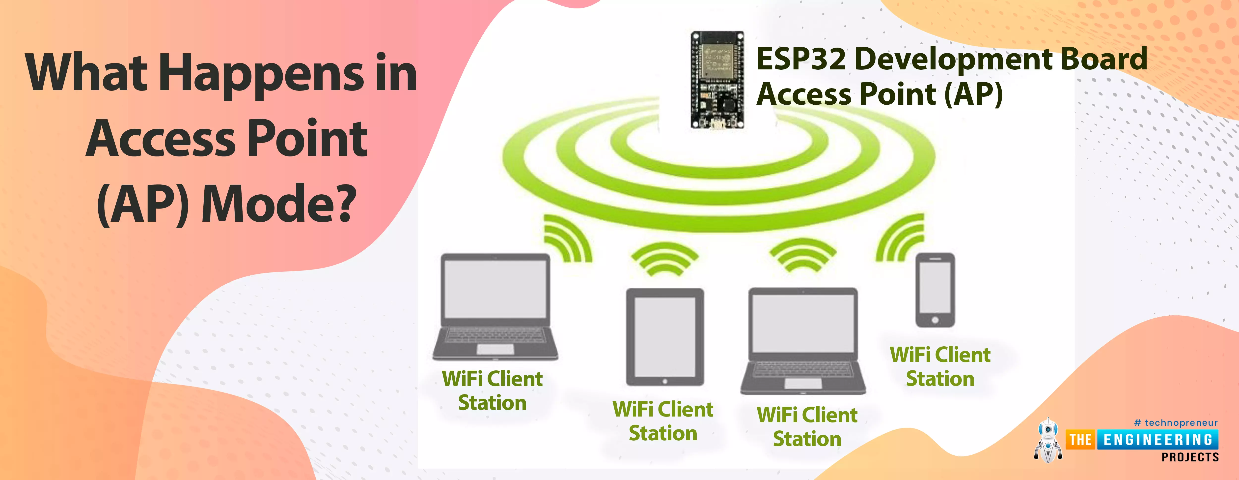
ESP32 can be operated as an access point (AP) or a Wi-Fi station (STA mode). So, in this tutorial, we will create an ESP32 web server in access point (AP) mode. Here's the video demonstration of ESP32 WebServer in Access Point Mode:
As I mentioned above, in our 2nd tutorial, we already discussed the basics of the ESP32 web server. So, in this tutorial, we will only discuss how to create the ESP32 in access point mode.
For detailed information about the basics of the ESP32 web server and how client-server communication takes place, fol ...
Hello readers, I hope you all are doing well. Welcome to the Section 2 (ESP32 Features) of the ESP32 Programming Series. ESP32 is equipped with numerous built-in features and in each chapter of this Section 2, we will explore one of these ESP32 features in detail.
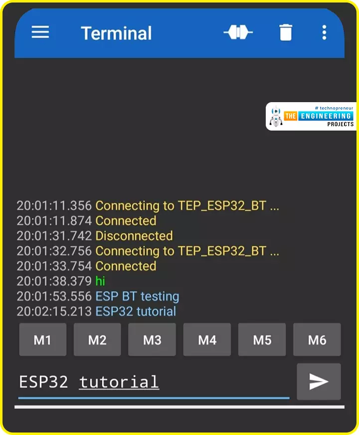
In the previous Section(Section 1: ESP32 IDEs), we installed different software IDEs to program ESP32 boards. Among these IDEs, we are going to use Arduino IDE for programming ESP32. So, I hope all of your tools are configured properly and you are ready to explore the built-in features of ESP32.Today's the 1st Chapter of Section 2, and here we will discuss How to communicate with ESP32 Bluetooth Classic from a smartphone using Arduino IDE.
Here's the video tutorial for ESP32 Bluetooth Classic:
ESP32 Wireless Features ...
Hello geeks, Welcome to our new project. As most readers have already seen the coffee vending machine or maybe you are drinking coffee while reading this article and if you are a tinker or a geek, it must have come to your mind how to make a coffee vending machine on your own. In today's tutorial, we are going to learn how to make a Smart Coffee Vending Machine using Arduino with Proteus Simulation for the same.
We can use this project for an engineering project’s showcase for electronics, electrical engineering students, and can be used in offices as well.
Coffee is the second most popular drink in the world and it is one of the oldest beverages of the world. According to Wikipedia, more than 2 billion cups of coffee are consumed every day in the ...
Hello readers, today we will learn about the messaging protocol supported by ESP32(called MQTT protocol), which is used for IoT applications. The communication protocol to be used for data transmission and connectivity in web-enabled devices depends upon the type of IoT application.
The Internet of Things (IoT) is a network of interconnected computing devices like digital machines, automobiles with inbuilt sensors, having unique identifiers and the ability to communicate data over a network without the need for human intervention.
Before implementation, let's first have a look at what is MQTT Protocol?
What is MQTT?
MQTT stands for Message Queuing Telemetry Protocol and is a messaging or communication protocol used for IoT applications.
In MQ ...
Hello readers, I hope you all are having fun in your lives. Welcome to the 2nd Chapter of Section-2 in the ESP32 Programming Series. In today's lesson, we'll go over another built-in feature of the esp32 module that helps it stand out from the competition: BLE or Bluetooth Low Energy. In the previous tutorial, we discussed the Classic Bluetooth in ESP32, which is considered the predecessor of Bluetooth Low Energy(which we are going to discuss today). We will first look at, what is BLE? and why is it used?, and then will design some examples to utilize the ESP32 BLE in Arduino IDE.
What is BLE?
There have been numerous adjustments and upgrades to Bluetooth's characteristics since its inception, where Bluetooth 4.0(also called BLE or Bluetooth Smart) is the most influential.
B ...
Hello readers, I hope you all are doing great. Today, we are going to start the second section of the ESP32 tutorial series and today's our first tutorial, where we will have a look at How to Create a Web Server with ESP32. In our previous tutorial, we introduced you to the basics of the ESP32 microcontroller. where we discuss How to set up Arduino IDE to program ESP32. In this tutorial, we will discuss creating a web server using the ESP32 module.One of the most interesting features of the ESP microcontroller series is its wireless connectivity via WiFi & Bluetooth. Wireless connectivity protocols supported by ESP32 are:
Wi-fi: 802.11b/g/n/e/i
Bluetooth : BLE(Bluetooth low energy) and V4.2
What is a Web server?
A web server is software or hardware that stores, processe ...
Hello friends, I hope you all are doing great. In today's tutorial, we are going to design a Proteus Simulation for Automatic Plant Watering System using Arduino. We have designed this project for engineering students as it's a common semester project, especially in electrical, electronics and mechatronics engineering.
The two most significant hazards to the agriculture industry are the need for extensive labor and a scarcity of water. According to the World Wildlife Fund (WWF) organization, water shortages might affect two-thirds of the world's population by 2025, putting both the ecosystem and human health at risk. The use of automatic plant watering systems eliminates both of these problems by watering plants at specified times and amounts whil ...
Hello everyone, I hope you're all doing well. In the previous lecture(Chapter 0: ESP32 Pinout), we discussed the ESP32 features & specs in detail. Today, we are officially starting this ESP32 Programming Series. In this ESP32 Programming Series, we will start with basic concepts and
will gradually move towards complex topics. I will try to keep this
ESP32 series as simple as I can. But still, if you encounter any issues,
please ask in the comments, will try to resolve the issues as soon as
possible.As ESP32 has numerous features & applications, so I have divided this series into different sections. I have named the 1st section "ESP32 IDEs". In this section, we will discuss different IDEs used to program ESP32 boards. In each Chapter of this section, we will install one of t ...
Security systems are widely suggested for homes as well as other locations. Everybody wants to take necessary steps to prevent infiltration at home, thus this security is necessary. Intruders nowadays may take advantage of almost any illegal activity and wreak havoc on a property's security. The security of one's home is a critical concern that everyone faces in the current day.
While there are certain devices on the market that may considerably help protect your house, some of them are excessively costly and need constant maintenance. Many devices regarding smart home security systems are available in the market but these are not user friendly according to the budget, the device we designed provides the user with a better interface with the help ...