ESP32 Hall Effect Sensor in Arduino IDE

Hello readers, I hope you all are doing great. Welcome to Section 5 of the ESP32 Programming Series. In this section, we are going to interface different Embedded Sensors with the ESP32 Microcontroller Board. ESP32 development board is featured with some inbuilt sensors(i.e. hall effect sensor, capacitive touch sensor) so, in the initial tutorials of this section, we will explore these built-in ESP32 sensors and in the later lectures, we will interface third-party sensors with the ESP32.

In today's lecture, we will discuss the working/operation of the ESP32 built-in Hall Effect Sensor. Hall Effect sensor is used to detect the variation in the magnetic field of its surroundings. So, let's first understand What's Hall Effect:

Where To Buy?
No.ComponentsDistributorLink To Buy
1ESP32AmazonBuy Now

What is the Hall Effect?

The Hall Effect phenomenon was first discovered by Edwin Hall in 1879. When current passes through a conductor, the electrons move in a straight line and thus the voltage difference across the conductor's surface remains zero, as shown in the below figure:

However, when a magnet is placed near the current-carrying conductor in a way that the direction of the magnetic field is perpendicular to the flow of current, the electrons get diverted and don't follow a straight line, which results in generating a small potential difference across the conductor's surface, as shown in the below figure:

This small potential difference generated because of magnetic field presence is called Hall Voltage. This magnetic field influence over the current-carrying conductor is termed the Hall Effect.

Hall Effect Sensor

A Hall Effect Sensor is a non-contact type embedded sensor, used to detect the presence & intensity of a magnetic field in its surroundings. Different third-party Hall Effect Sensors available in the market are shown in the below figure:

  • A normal Hall Effect Sensor Pinout consists of 3 Pins i.e.
  1. Vcc: Normally +5V, few +3.3V are also available.
  2. GND: We need to provide Ground here.
  3. OUT: The Output Pin to give the sensor's response.
  • When a perpendicular magnetic field is placed near a Hall-effect sensor, it changes the status of its Output Pin.
  • The analog Hall Effect Sensors can also detect the strength of the magnetic field i.e. greater the magnetic field greater will be the sensor's output or voltage deviation.

Applications of Hall Effect sensor

  • In an Automotive system, Hall Sensors are used to detect speed, distance, position etc.
  • Used in Proximity sensing.
  • Used in Current sensing.
  • Used in Anti-lock braking system.
  • Used in Internal combustion engines to assist with ignition timing.
  • To switch an electric circuit ON and OFF.

Hall Effect Sensor in ESP32

In ESP32, the Hall effect sensor is located inside the ESP-WROOM-32 metallic cover. As the Hall Effect sensor is a non-contact type, it doesn't have to be in contact with the magnet. We just need to place the magnet above this metallic sheet and the ESP32 Hall Effect sensor will detect it.

Programming ESP32 Hall Effect Sensor using Arduino IDE

To understand the working of the Hall sensor with ESP32, let's test the builtin ESP32 example:

  • You can find the code through File> Examples> ESP32 > Hall Sensor, as shown in the below figure:

Arduino IDE code

Here's the code for this ESP32 Hall Sensor example:

int val = 0;

void setup()
{
   Serial.begin (9600);
}

void loop() 
{
   val = hallRead();
   Serial.print ("sensor value = ");
   Serial.println (val);//to graph

   delay(100);
}

Code Description

The code is quite simple, where the hallRead() function is called to read the hall sensor value, store it into a variable and then print it on the Serial monitor. Finally added a small delay to get the next value. Let me explain the code line by line for the beginners:

Variables Declaration

  • The first step will be the declaration of an integer-type variable to store the hall sensor value. The initial value assigned to the variable is zero.
int val = 0;

Setup() Function

  • Inside the setup function, the only task is to initialize the serial port at a 9600 baud rate for serial communication.
void setup()
{
   Serial.begin (9600);
}

Loop() Function

  • Inside the loop function, we called a function ‘hallRead()’ to read the sensor value and store those readings into the variable ‘val’.
  • Printed the sensor readings on the serial monitor or serial plotter using serial.println() function.
  • A delay of 0.3 sec is added at the end.
void loop() 
{
   val = hallRead();
   Serial.print ("sensor value = ");
   Serial.println (val);//to graph

   delay(100);
}

ESP32 Hall Effect Sensor - Testing

  • After successfully uploading the code into ESP32, open the serial plotter or serial monitor to monitor the results.
  • Place a magnet near the ESP32 board.
  • The sensor reading will increase/decrease depending on the magnet pole(i.e. North or South Pole) facing the Hall sensor.
  • Now click on Tools > Serial Plotter to visually analyze the sensor's output.
  • The Serial Plotter of our project is shown in the below figure:
  • As you can see in the above figure, the sensor is giving negative output when facing the North Pole of the magnet.
  • In the case of a South Pole, the sensor's output is positive.
  • In the absence of a magnetic field, the sensor's output is almost 0.
  • The distance between the magnet and the Hall sensor decides the amount of potential difference generated.
  • The greater the distance between the two, the smaller the hall voltage or potential difference will be.
  • We have attached an image from the Arduino IDE serial monitor for your reference.

This concludes the tutorial. I hope you found this helpful, test it out and if feel any difficulty, let me know in the comments. In the next tutorial, we will have a look at another built-in sensor of ESP32 i.e. Capacitive Touch Sensor. Thanks for reading.

Car Parking System with Automatic Billing using Arduino

Hi Geeks, welcome to our new project. Our new project is one of the most common issues you’ve seen in your cities. In this project, we are going to make a car parking system with automatic billing. In the entire world, there are an estimated 1.4 billion cars on the road, which is absolutely great news if we are considering the development of the Automobile industry. But the most serious issue is that the number of cars exceeds the number of available parking places, resulting in traffic congestion. Damaged cars due to this lack of space, fewer parking locations, lack of parking signage, informal parking, and overcharging for parking are just a few of the issues.

People are still choosing manual parking methods, which have a number of drawbacks, such as searching for a vacant spot in a parking lot without knowing if the lot is full or not, resulting in time and fuel waste. Vehicle safety is also a concern that may be addressed. We've all been in a position when we've spent a long time looking for parking at a location just to discover that none is available. You would think that if you knew the slots were full, you would've ended up finding another parking spot.

Based on these scenarios, we came up with the idea of a Car Parking System with Automatic Billing which will also reduce manpower such as security, booth attendants, etc., required in parking lots. Everything in the modern day is automated, and with this project, we can automate this procedure using simple electronics components and Arduino. Let's get started.

Where To Buy?
No.ComponentsDistributorLink To Buy
1DS1307AmazonBuy Now
2Keypad 4x3AmazonBuy Now
3LCD 20x4AmazonBuy Now
4Arduino UnoAmazonBuy Now

Software to install:

Instead of using real components, we'll use the Proteus Simulation tool to design this project. It's also a good habit to experiment with simulations before attempting to build everything with real components. By simulating an issue that may develop when working on actual components, we may identify the problem and avoid any damage to our components.

Proteus is an interesting software that lets you model and build electronics circuits. Despite having a huge library of electronics components, Proteus software lacks pre-installed modules such as Arduino boards, Ultrasonic sensors, RTC modules, LCD modules, and so on.

Now, we’ll start installing the libraries, which is needed for our project:

By clicking the button below, you can download the entire project, including Proteus Simulation and Arduino Code.

Project Overview:

These are required components for Accident Detection, which are as follows:

  • Arduino Uno: Arduino Uno is a development board from the Arduino family, which is the main component of this project and acts as the brain. The Microcontroller i.e., Arduino is responsible for the decisions that are going to be processed in the project.
  • 20X4 LCD display: It is used to display the information regarding parking slots and shows the amount that has to be paid by the driver at the Check out time from the parking lot.
  • Ultrasonic Sensor: It is used to calculate the distance from the car to the entry gate and detects that a car has reached near the gate.
  • RTC Module: Real-Time Clock Module is used to calculate the time and plays a key role in determining the total amount for the parking slot.

Components Needed:

  1. Arduino Uno
  2. LCD Module
  3. Ultrasonic Sensor
  4. Keypad 3x4
  5. LED’s
  6. RTC Module

Components Details

Arduino Uno:

  • Any Arduino development board can be used in this project, however, we'll be using Arduino UNO development boards. The Arduino UNO is a programmable, open-source microcontroller board from the Arduino series.
  • It contains an ATMega328P microcontroller from Atmel, which has an 8-bit RISC processing core and 32 KB of flash memory.
  • The Arduino UNO includes 14 digital I/O pins i.e., D0 - D13, with a resolution of 10 bits, including 6 PWM pins and 6 analog I/O pins (0-1024) i.e., A0 - A5.
  • Only one hardware UART peripheral pin, one I2C peripheral pin, and one SPI peripheral pin are available on the Arduino UNO (however we can use other pins for UART communication using the SoftwareSerial package in Arduino).
  • The Arduino UNO can be powered from a voltage range of 7 to 12 volts, the voltage regulator embedded inside the board will reduce the excess voltage. however, not more than 9 volts is suggested since it might harm the Arduino board.
  • A USB-B cable (the same cable that we used to upload the sketch to Arduino UNO), a DC power jack, and the Vin pin on the board may all be used to power Arduino UNO.
  • Using the Arduino IDE Software, the sketch is written and uploaded to the Arduino UNO. It is completely free, simple to comprehend, and easy to combine with a variety of electronic components.

LCD Module:

In this project, an LCD display is used to present the information to the user.
  • LCD stands for Liquid Crystal Display, and it is a type of display that is made using Liquid Crystal technology.
  • LCDs come in a variety of sizes; in this project, we utilized a 20X4 size.
  • The 20X4 indicates that it can show 80 ASCII characters at once.
  • The LCD has 16 pins. In which the necessary pins are connected in the circuit.
  • It contains eight data pins, one Read/Write select pin, one Register mode pin, one Enable pin, two backlight pins, two power supply pins, and one contrast control pin.
  • In the LCD, there are primarily two types of registers: Command Register and Data Register.
  • When the RS(Register Select) pin is set to logic high, the data register mode is selected, and when it is set to logic low, the command register mode is selected.

The RS pin will be set to logic high to display the data on the LCD.

Ultrasonic Sensor (HR-SR04):

  • The HC-SR04 ultrasonic sensor employs SONAR to estimate the distance of an object.
  • The ultrasonic sensor sends out a signal wave that has a frequency of about 40 kHz, with a high pitch that humans are unable to hear.
  • From 2 cm to 400 cm (1" to 13 feet), it provides the detection of objects with high accuracy and the pulse will not be disturbed by sunlight or any climate conditions.
  • It consists of four pins, Trig, Echo, VCC, and GND.
  • The operating voltage of an Ultrasonic sensor is 5V. We can connect the VCC pin of the sensor with 5V output in Arduino and the sensor will work perfectly.
  • Ultrasonic sensors work on the principle of sound wave reflection.
  • The trig pin works as an ultrasound transmitter which emits the high frequency sound waves in pulses. And the echo pin works as an ultrasound receiver. It receives the reflected ultrasonic waves which are bounced back from the object.
  • We calculate the distance from the object and the sensor by measuring the time taken between the transmission and the reception of the signal.
  • To measure the distance of sound traveled from trig to echo,

Distance = (Time x SpeedOfSound) / 2.

Speed of Sound: 340 meters per second i.e., 0.034
  • The easiest way to calculate the distance in cm is using this formula,

Distance in Centimeters = (( Time taken by pulse signal (in microseconds) / 2) / 29)

Keypad 3x4:

  • A keypad button is used for user input.
  • The keypad's buttons are arranged as a matrix of 3x4. Which means it has four rows and three columns.
  • They work on the principle of membrane keypads. They are very flexible and feel like a push button.
  • The switch between a column and a row trace is closed when a button is pressed, allowing current to pass between a column pin and a row pin.
  • A copper padding and line beneath the pad connects each switch in a row to the other switches in the row.

RTC Module (DS1307):

  • The DS1307 IC is a low-cost, high-accuracy RTC that uses the I2C protocol as an interface.
  • The DS1307 features a backup battery mounted on the rear of the module to maintain track of time even if the main power supply is disconnected.
  • When necessary, the chip shifts between the primary and backup power sources.
  • The RTC records information such as seconds, minutes, hours, days, dates, months, and years.
  • This module includes a Reference clock, programmable Square wave output(SQW), SCL, SDA, VCC, and GND.
  • Automatic Power-Fail Detect and Switch Circuitry
  • Low Power Operation Extends Battery-Backup Run Time.
  • The RTC module works on operating voltage 5V.

Proteus Simulation of Car Parking System:

Now, it’s time to start the design of the Proteus Simulation of our Car parking system

  • Before you begin designing, make sure Proteus is installed on your computer and that you have downloaded all of the necessary libraries.
  • We'll need Arduino libraries and LCD modules for this project. Make sure you've read the section on using libraries in Proteus software.
  • Let's begin by creating a new project, and importing all of the required components, and placing them within the working area.
  • Select all of the components from the Proteus component library that we'll require.

Circuit Diagram and Working:

After importing all required components to the workplace, let’s move to connecting them.

  • Starting with the connection of LEDs, we are using digital pins 2,3,4,5,6 for LEDs. Connect the positive side of the LEDs to the Arduino UNO board.
  • After that, connect the Ultrasonic sensor module’s Trig pin and Echo pin to digital pin 8 and 7 respectively, Vcc to 5v volt power and GND to Ground.
  • In the simulation. it will not be possible to change the distance from the Ultrasonic sensor so for that we have connected a potentiometer with the test pin of the module.
  • Now start the connection of the Keypad, as this is a 3x4 keypad so it will use 3 pins for columns and 4 pins for rows.
  • As there are limited digital pins on Arduino UNO, we have to use the analog pins of Arduino UNO as digital pins.
  • Now let’s connect the row pins A, B, C, D with A0, A1, A2, A3 respectively and column pins 1, 2, 3 with digital pins 9, 10, 11 respectively. And we have to connect the pins in an exact manner.
  • RTC module uses the I2C protocol, so we will connect SDA and SCL pins to Arduino UNO’s SDA (A4) and SCL (A5) pins respectively. Vcc with 5v power supply and Gnd with the ground.
  • As there are no pins left for connecting the LCD module therefore we will use an I2C GPIO expander for connecting the LCD module.
  • Connect the SDA and SCL pins of GPIO expander with the SDA and SCL pins of Arduino UNO and we have to set the slave address of GPIO expander, for that we will connect the A0, A1, A2 pins with ground, that will set the I2C slave address to 0x20.

Now we have done the circuit, it’s time to move to the coding side of this project.

Arduino code for the accident detection:

  • We must add relevant libraries, which operate as header files in programming languages before we begin writing the code.
  • So, if the necessary libraries aren't already installed in the Arduino IDE, we'll need to download them first.
  • We can install Arduino libraries by going to 'Sketch > Include Library > Manage Library' in the Arduino IDE. In the library manager, we can now search for our essential libraries. The libraries can also be installed via zip files.
  • We can download the libraries from the above instruction, but if they are not available, we can use the following links to download the zip files of libraries.
  • Here we used “Wire.h” to enable I2C communication and it is pre-installed.
  • “LiquidCrystal_I2C.h” is used for the LCD.
  • “Keypad.h” is used for the integration of the keypad module.
  • “RTClib.h” is the library for RTC modules.
  • Let’s declare the pins for modules. We mainly use two pins i.e. Trig and Echo for the object detection and distance calculation. Here we have connected the Echo pin to D7 and Trig pin to D8 in Arduino Uno and an array for storing the pins for LEDs as D2, D3, D4, D5, D6. Two arrays for storing the pins for keypads such as rowPins for A0, A1, A2, A3 pins and colPins for D9, D10, D11.
  • Now, Let’s declare configuration related variables for the keypad. Here we are declaring variables to store the number for Rows and Columns. We will use a 2D char array named ‘hexaKeys’ for storing the symbols of keypad.
  • Now declare some general variables for storing the values for ultrasonic sensors, charge, total charged amount, check-in time and check-out time of vehicles.
 
  • Now, Let’s declare the objects of the modules.
 
  • The “customkeypad” is initializing an instance of class NewKeypad. The statement is going to map these symbols with the pins we have declared to connect with Arduino. Hence, it will map according to the row and column pins.
  • Next, we are initializing the LCD display with an I2C serial interface and setting the address to 0x20 Hex.
  • And we are declaring an object named ‘rtc’ for the “RTC_DS1307” module.

Void Setup():

  • The void setup() is an important function in the sketch that will execute only once in the whole program. The input, output, and other serial communication initializations are done inside the void setup. Let’s write the void setup sketch now.
  • In this setup function, firstly we have enabled the serial communication with “Serial.begin” with the default baud rate of 9600.
  • Next, we are initializing the LCD and turning on the backlight of the LCD.
  • We have already declared the Trig and Echo pins before in the declaration part, and now we are going to set them up as output and input pins respectively.
  • There may be a doubt why we have declared a Trig as output and Echo as input. That is because the Trig pin will generate the ultrasonic wave pulses and the Echo pin will work as a receiver for reflected waves.
  • We are using five led’s for the five slots in the parking lot and to make the logic simpler, declare the led pins as output mode.
  • Now, we are printing a line in the serial monitor and LCD. We are using the cursor function and printing “Made by” in the first row and “Tushar Gupta” in the second row. (0,0) is representing (column, row) in the LCD.
  • After printing the line, clear the LCD screen.
  • Now, we are trying to initialize the RTC module and if the RTC is not found, it will print that “Couldn’t find RTC”. and halt the further processing of code.

  • After successful initialization of the RTC module we will know if the RTC module is running already , if yes then we don’t have to set the time explicitly otherwise we have to .
  • We will use a “dist()” function to calculate the distance using the formula mentioned in component details.
  • For the calculation of distance, we will generate the pulses using the Trig pin.
  • To generate the pulses , switch the TRIGpin to LOW for 4 microseconds and then HIGH for 10 microseconds then again LOW .
  • By using ‘pulseIn’ we can calculate the time duration the wave has taken to travel back from the object.
  • “ distance = duration*(0.034/2); ” and here 0.034 is the speed of sound and with this formula, we can calculate the distance in cm and set the threshold values.
  • “pulseIn” takes two arguments, first pin number and second logical state. This will read the pin for logic HIGH and return the time period in which that pin was at a HIGH state.
  • For more knowledge of “pulseIN “ refer to this link: pulseIN function

Void loop():

  • It is the next most important function of Arduino code/ sketch. The “void loop()” will run after the execution of “void setup()”.
  • We'll write the code required to run in a continuous loop in this part. So here we'll write our main application code.
  • Here, we are going to first discuss the Automatic billing part near the gate in our parking system.
  • In the loop function, the Date and Time of that current time are set by “rtc.now”, and the user will enter his slot number in the keypad when he/she is exiting from the slot.
  • The user will click the allocated slot number on the keypad and we are collecting that in the “customkey” variable using the “getkey” function.
  • The serial monitor will print the custom key entered by the user. Then we will check the slot status by “digitalRead (led[i])”.
  • If the led status is HIGH which means the slot was occupied now we will generate the bill for that slot and display that amount on the LCD display for1 second after clear the LCD and set that slot LED to LOW state.
  • The next step we are going to do is to calculate the total amount according to his vehicle staying inside the parking lot. And for that, we can do the simple calculation that is “amount = charge*(gotime [i] - cometime [i]) ;”.
  • We have already declared the charge amount in the above sections of the program. The charge will be multiplied by “go time - come time”, which is the total time the vehicle stayed inside the lot. And the multiplied result of stay time and charge is the final amount the driver has to pay for his parking slot.
  • Now, the driver can pay the amount and exit through the gate. Here, after a second delay, we are clearing the LCD display.
  • “What if the driver pressed any wrong key which has a free slot?” That might be the question in your mind. Well, we can cover that condition with an else statement, where we can print “The slot is already empty” on the LCD and let the driver know that he has entered the wrong key in the keypad near the exit gate.
  • Till now, we have seen the Automatic billing logic near the exit gate. But let’s see what is the slot allocation process at the entry gate.
  • As we have already calculated the distance with the ultrasonic sensor using the “dist()” function, we can set the distance limit to 100cm before the gate, and when a car reaches the entry gate the allocation of the slot will be started.
  • The “for loop” here will see what are the slots showing Low/empty in the parking and allocate that empty one to the car by printing “Park your car at ” and “Slot i” in the LCD.
  • As this slot was allocated, we have to write this LED as High which indicates the slot is not empty. This is the reason where the slot led is high at the exit gate when the user pressed his slot number in the keypad. We are turning on the LED when we are allocating the slot to a car.
  • Now we also have to collect the “come time” by the RTC module for further calculation at the end or near the exit gate.
  • We are implementing an if statement where the all LEDs are high, which means all the slots are filled, the LCD should print (“No more slots”) and inform the driver and clear the LCD screen.

Results / Working:

We have completed the Proteus simulation circuit and Arduino code for the Car Parking project. And it is ready for testing.

  • Before going to start the simulation, we have to add the hex file of our application code in the Arduino UNO module in Proteus and a hex code for the ultrasonic sensor also.
  • To add the hex file, click on the Arduino UNO and a new window will open then click on the Program files, there we will browse to our hex file.
  • In the same way, we can add a hex file for the ultrasonic sensor.
  • Now start the simulation, on the first boot of the circuit, LCD will display the welcome message and the same message will be displayed in the serial terminal also
  • Just for debugging purposes, we are continuously printing the ultrasonic sensor values.
  • In the simulation to change the distance between the vehicle and ultrasonic sensor we have used a potentiometer. Now change the value on the potentiometer.

As we can see that for 50% value on the pot ultrasonic sensor value is near to 500 cm and for 77% value on the pot ultrasonic sensor value is near to 850 cm.

  • Let's test the condition when the vehicle approaches the sensor, to satisfy that condition the object must be at a distance of less than 100 cm. For that, we have to change the pot value. Set the pot value near to 10 %.
  • After that LCD will display a message if that spot is vacant like “Park your car at Slot 1” and LED for the same location will glow.
  • To take the bill for any location press the keypad for that location number let’s suppose here the location is 1 so we will click on ‘1’
  • After that, it will generate the bill with the total charged amount and the LED for that location will be turned off.
  • In case if we click any slot button which is already vacant then LCD will display the message for the slot is vacant.

Here it is not visible which button on the keypad has clicked but suppose we have clicked ‘1’ and if that location is vacant then it will display that message.

  • Let’s take another case when we want to park another car. Now slot 1 is already busy so we will park at slot 2.
  • This time when the sensor value changes less than 100 cm, then the LCD display will show “Park your car at slot 2” because slot 1 is preoccupied.
  • In the image, we can see that both LEDs are glowing as both slots are occupied now.
  • For billing, we will click the button on the keypad for the respective slot.
  • Let’s take a case when all slots are occupied. Here we can see all slot LEDs are glowing.
  • Now we will try to park another car. Then LCD will display ‘no more slot’ as there is no vacant slot available at parking.

I hope you have a good understanding of how our Car parking system project works and that you have liked it. Although it’s a tough nut to crack in the first read, I strongly recommend you to read the logic part twice for better understanding. I believe we have covered almost everything, please let us know if you have any questions or suggestions in the comments section.

Thank you very much for reading this project. All the best for your projects!

ESP32 Over The Air (OTA) Web Updater

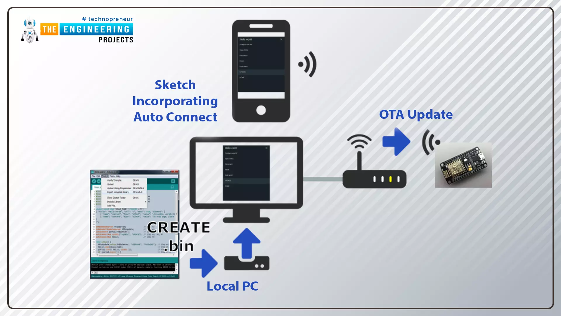
Hello readers, I hope you are all doing great. In this tutorial, we are going to discuss the OTA web updater on the ESP32.

We already covered the fundamentals of OTA programming in ESP32, in our previous tutorial where we used the Arduino IDE to upload OTA code into the ESP32 module using the network port.

In the OTA web updater, you need to create a web server page for OTA programming.

[caption id="attachment_166886" align="aligncenter" width="1920"] ESP32 OTA web updater[/caption]

Fig.1 ESP32 OTA web updater

Where To Buy?
No.ComponentsDistributorLink To Buy
1ESP32AmazonBuy Now

Over the Air Web Updater

  • "Over-the-air" refers to the ability to wirelessly download an application, configuration, or firmware to internet-enabled devices, also known as IoT. (OTA). It functions similarly to our computers, laptops, tablets, and phones.
  • Instead of using a serial port and a wired medium to upload a code, the OTA web updater allows the user to update the code or firmware wirelessly via a web server.
  • When sensor nodes are frequently placed in remote or difficult-to-reach locations, OTA programming can be used.

Steps to implement an OTA web updater using ESP32

  • Using the serial communication port, upload the code containing the instructions to enable the OTA web updater (so that in the future you can update the code using a browser instead of a wired medium).
  • The code uploaded via the serial port will launch a web server, allowing you to upload new code over the air.
  • The new code, which has been uploaded using a web server, should contain instructions to keep the OTA web updater enabled on the ESP32 board so that you can use the OTA programming feature in future applications as well.
  • Create a .bin using Arduino IDE compiler and upload the file on the server.

Fig. 2

Code for OTA web updater implementation in ESP32

In this tutorial, we will discuss only the OTA web updater method using Arduino IDE and ESP32 dev-Kit V1 module.

If you want to know more about the basics of ESP32 and how to get started with Arduino IDE, then read Introduction to ESP32 Programming Series.

  • You can find the code through File> Examples> ArduinoOTA> BasicOTA.
  • An image has been attached below for reference:

Fig. 3

  • This code should be uploaded serially through a serial communication port only then you can access the OTA web updater feature.

Code

#include <WiFi.h> #include <WiFiClient.h> #include <WebServer.h> #include <ESPmDNS.h> #include <Update.h>   const char* host = "esp32"; const char* ssid = "SSID"; const char* password = "password";   WebServer server(80);   /* * Login page */   const char* loginIndex = "<form name='loginForm'>" "<table width='20%' bgcolor='A09F9F' align='center'>" "<tr>" "<td colspan=2>" "<center><font size=4><b>ESP32 Login Page</b></font></center>" "<br>" "</td>" "<br>" "<br>" "</tr>" "<td>Username:</td>" "<td><input type='text' size=25 name='userid'><br></td>" "</tr>" "<br>" "<br>" "<tr>" "<td>Password:</td>" "<td><input type='Password' size=25 name='pwd'><br></td>" "<br>" "<br>" "</tr>" "<tr>" "<td><input type='submit' onclick='check(this.form)' value='Login'></td>" "</tr>" "</table>" "</form>" "<script>" "function check(form)" "{" "if(form.userid.value=='admin' && form.pwd.value=='admin')" "{" "window.open('/serverIndex')" "}" "else" "{" " alert('Error Password or Username')/*displays error message*/" "}" "}" "</script>";   /* * Server Index Page */   const char* serverIndex = "<script src='https://ajax.googleapis.com/ajax/libs/jquery/3.2.1/jquery.min.js'></script>" "<form method='POST' action='#' enctype='multipart/form-data' id='upload_form'>" "<input type='file' name='update'>" "<input type='submit' value='Update'>" "</form>" "<div id='prg'>progress: 0%</div>" "<script>" "$('form').submit(function(e){" "e.preventDefault();" "var form = $('#upload_form')[0];" "var data = new FormData(form);" " $.ajax({" "url: '/update'," "type: 'POST'," "data: data," "contentType: false," "processData:false," "xhr: function() {" "var xhr = new window.XMLHttpRequest();" "xhr.upload.addEventListener('progress', function(evt) {" "if (evt.lengthComputable) {" "var per = evt.loaded / evt.total;" "$('#prg').html('progress: ' + Math.round(per*100) + '%');" "}" "}, false);" "return xhr;" "}," "success:function(d, s) {" "console.log('success!')" "}," "error: function (a, b, c) {" "}" "});" "});" "</script>";   /* * setup function */ void setup(void) { Serial.begin(115200);   // Connect to WiFi network WiFi.begin(ssid, password); Serial.println("");   // Wait for connection while (WiFi.status() != WL_CONNECTED) { delay(500); Serial.print("."); } Serial.println(""); Serial.print("Connected to "); Serial.println(ssid); Serial.print("IP address: "); Serial.println(WiFi.localIP());   /*use mdns for host name resolution*/ if (!MDNS.begin(host)) { //http://esp32.local Serial.println("Error setting up MDNS responder!"); while (1) { delay(1000); } } Serial.println("mDNS responder started"); server.on("/", HTTP_GET, []() { server.sendHeader("Connection", "close"); server.send(200, "text/html", loginIndex); }); server.on("/serverIndex", HTTP_GET, []() { server.sendHeader("Connection", "close"); server.send(200, "text/html", serverIndex); });   /*handling uploading firmware file */ server.on("/update", HTTP_POST, []() { server.sendHeader("Connection", "close"); server.send(200, "text/plain", (Update.hasError()) ? "FAIL" : "OK"); ESP.restart(); }, []() { HTTPUpload& upload = server.upload(); if (upload.status == UPLOAD_FILE_START) { Serial.printf("Update: %s\n", upload.filename.c_str()); if (!Update.begin(UPDATE_SIZE_UNKNOWN)) { //start with max available size Update.printError(Serial); } } else if (upload.status == UPLOAD_FILE_WRITE) { /* flashing firmware to ESP*/ if (Update.write(upload.buf, upload.currentSize) != upload.currentSize) { Update.printError(Serial); } } else if (upload.status == UPLOAD_FILE_END) { if (Update.end(true)) { //true to set the size to the current progress Serial.printf("Update Success: %u\nRebooting...\n", upload.totalSize); } else { Update.printError(Serial); } } }); server.begin(); }   void loop(void) { server.handleClient(); delay(1); }

Code Description

The first task is to add the header files, required to perform over the air (OTA) web updates using the ESP32 module.
  • WiFi.h : This header file allows the ESP32 board to connect to the internet. It can serve either as a server or a client.
  • ESPmDNS.h : This library is used to implement multicast DNS query support for the ESP32 chip. A multicast UDP service is used to provide local network service.
  • WiFiClient.h : It is used to create a client that can connect to a specific port and IP address.

Fig. 4

  • Enter the SSID and password.

Fig. 5

  • You can style the HTML page anytime as per your requirements or use the default style given in the example code.

Setup()

  • Initialize the serial monitor at a 115200 baud rate.
  • WiFi.begin() function is used to initialize the Wi-Fi module with Wi-Fi credentials used as arguments.

Fig. 6

  • Wait until the ESP32 is connected to the Wi-Fi network.

Fig. 7

  • If the device is connected to a local Wi-Fi network then print the details on the serial monitor.
  • WiFi.localIP() function is used to fetch the IP address.
  • Print the IP address on the serial monitor using Serial.println() function.

Fig. 8

  • Use multicast Domain Name System (mDNS) for hostname resolution.
  • Hostname has been defined as a global variable at the beginning of code.
  • Start the mDNS responder for esp32 or host using MDNS.begin() function.

Fig. 9

  • Return the index page which is stored in serverIndex.
  • Send the status OK (200 represents ‘OK’) to inform the client.

Fig. 10

  • Handling the uploading of firmware files.

Fig. 11

  • Start uploading the new firmware into the ESP32 board.

Fig. 12

  • Server.begin() function will start the server to listen for incoming connections.

Fig. 13

Loop()

  • Server.handleCLient() function is used to handle the client devices.
  • It will monitor the client devices and provide the requested HTML page.

Fig. 14

  • After successfully uploading the code into ESP32 board using serial communication port, open the serial monitor with 115200 baud rate.
  • Press EN or enable button from the ESP32 board.
  • You can see the IP address printed on the serial monitor, once the ESP32’s Wi-Fi module is connected to wi-fi network.
  • We have attached a screenshot below for your reference:

Fig. 15 Serial monitor

Testing

  • Now the ESP32 module is ready for over the air (OTA) programming.
  • For testing the OTA web updater, remove the ESP32 module from your computer and power the ESP32 board using another power source.
  • Open the browser and enter the IP address from the Serial Monitor as shown in the above image.
  • A web page with an IP address of 168.43.223 is shown below:

Fig. 16

  • Enter the username and password on the login page. As per the example code:
Username: admin Password: admin
  • You can change the username and password details if you wish to.
  • Click on Login.
  • A new browser page with URL 192.168.43.223/serverIndex will be displayed on the screen, as shown below:

Fig. 17

  • You can style the browser page as per your requirements.

Test code

  • Write a new code in Arduino IDE.
  • The code should contain two sections:
  1. The instructions to keep OTA web updater feature enabled
  2. Instructions to blink the LED (you can replace the LED code with another code as per your requirements).
#include <WiFi.h> #include <WiFiClient.h> #include <WebServer.h> #include <ESPmDNS.h> #include <Update.h>   const char* host = "esp32"; const char* ssid = "SSID"; const char* password = "password";   //variabls to blink without delay: const int led = 2; unsigned long previousMillis = 0; // will store last time LED was updated const long interval = 1000; // interval at which to blink (milliseconds) int ledState = LOW; // ledState used to set the LED   WebServer server(80);   /* * Login page */   const char* loginIndex = "<form name='loginForm'>" "<table width='20%' bgcolor='A09F9F' align='center'>" "<tr>" "<td colspan=2>" "<center><font size=4><b>ESP32 Login Page</b></font></center>" "<br>" "</td>" "<br>" "<br>" "</tr>" "<td>Username:</td>" "<td><input type='text' size=25 name='userid'><br></td>" "</tr>" "<br>" "<br>" "<tr>" "<td>Password:</td>" "<td><input type='Password' size=25 name='pwd'><br></td>" "<br>" "<br>" "</tr>" "<tr>" "<td><input type='submit' onclick='check(this.form)' value='Login'></td>" "</tr>" "</table>" "</form>" "<script>" "function check(form)" "{" "if(form.userid.value=='admin' && form.pwd.value=='admin')" "{" "window.open('/serverIndex')" "}" "else" "{" " alert('Error Password or Username')/*displays error message*/" "}" "}" "</script>";   /* * Server Index Page */   const char* serverIndex = "<script src='https://ajax.googleapis.com/ajax/libs/jquery/3.2.1/jquery.min.js'></script>" "<form method='POST' action='#' enctype='multipart/form-data' id='upload_form'>" "<input type='file' name='update'>" "<input type='submit' value='Update'>" "</form>" "<div id='prg'>progress: 0%</div>" "<script>" "$('form').submit(function(e){" "e.preventDefault();" "var form = $('#upload_form')[0];" "var data = new FormData(form);" " $.ajax({" "url: '/update'," "type: 'POST'," "data: data," "contentType: false," "processData:false," "xhr: function() {" "var xhr = new window.XMLHttpRequest();" "xhr.upload.addEventListener('progress', function(evt) {" "if (evt.lengthComputable) {" "var per = evt.loaded / evt.total;" "$('#prg').html('progress: ' + Math.round(per*100) + '%');" "}" "}, false);" "return xhr;" "}," "success:function(d, s) {" "console.log('success!')" "}," "error: function (a, b, c) {" "}" "});" "});" "</script>";   /* * setup function */ void setup(void) { pinMode(led, OUTPUT);   Serial.begin(115200);   // Connect to WiFi network WiFi.begin(ssid, password); Serial.println("");   // Wait for connection while (WiFi.status() != WL_CONNECTED) { delay(500); Serial.print("."); } Serial.println(""); Serial.print("Connected to "); Serial.println(ssid); Serial.print("IP address: "); Serial.println(WiFi.localIP());   /*use mdns for host name resolution*/ if (!MDNS.begin(host)) { //http://esp32.local Serial.println("Error setting up MDNS responder!"); while (1) { delay(1000); } } Serial.println("mDNS responder started"); /*return index page which is stored in serverIndex */ server.on("/", HTTP_GET, []() { server.sendHeader("Connection", "close"); server.send(200, "text/html", loginIndex); }); server.on("/serverIndex", HTTP_GET, []() { server.sendHeader("Connection", "close"); server.send(200, "text/html", serverIndex); }); /*handling uploading firmware file */ server.on("/update", HTTP_POST, []() { server.sendHeader("Connection", "close"); server.send(200, "text/plain", (Update.hasError()) ? "FAIL" : "OK"); ESP.restart(); }, []() { HTTPUpload& upload = server.upload(); if (upload.status == UPLOAD_FILE_START) { Serial.printf("Update: %s\n", upload.filename.c_str()); if (!Update.begin(UPDATE_SIZE_UNKNOWN)) { //start with max available size Update.printError(Serial); } } else if (upload.status == UPLOAD_FILE_WRITE) { /* flashing firmware to ESP*/ if (Update.write(upload.buf, upload.currentSize) != upload.currentSize) { Update.printError(Serial); } } else if (upload.status == UPLOAD_FILE_END) { if (Update.end(true)) { //true to set the size to the current progress Serial.printf("Update Success: %u\nRebooting...\n", upload.totalSize); } else { Update.printError(Serial); } } }); server.begin(); }   void loop(void) { server.handleClient(); delay(1);   //loop to blink without delay unsigned long currentMillis = millis();   if (currentMillis - previousMillis >= interval) { // save the last time you blinked the LED previousMillis = currentMillis;   // if the LED is off turn it on and vice-versa: ledState = not(ledState);   // set the LED with the ledState of the variable: digitalWrite(led, ledState); } }

Test Code Description

  • We are using the same old code with an additional LED blinking part.
  • In this code, we are using inbuilt LED for testing.
  • Define the GPIO pin to which LED is connected.
  • GPIO 2 is connected to the inbuilt LED.
  • To add delay, we are using timers instead of delay() function.
  • The variable interval is defining the time delay.
  • Set LED’s state to low.

Fig. 18

Arduino Loop() Function

  • Blink the LED after every 1000ms or 1sec delay as defined in variable ‘interval’.

Fig. 19

How to generate a bin file

  • Compile the code in Arduino IDE.
  • Go to Sketch > Export compiled Binary or press Crl+Alt+S to generate .bin file.

Fig. 20

Fig. 21 bin file

  • Upload the .bin file on the browser with 192.168.43.223/serverIndex URL and click on update option.
  • At 100% progress the inbuilt LED from the ESP32 board will start blinking.

Fig 22

Fig. 23 LED blink

  • Similarly, you can upload a new code using over the air web updater.

This concludes the tutorial. I hope, you found this helpful and I hope to see you soon for the new ESP32 tutorial.

Simple 4-Way Traffic Light Control using Arduino

Hello friends, I hope you’re all well and healthy. In today’s tutorial, we will be going through a simple, yet effective practice to design a 4-way traffic light simulation in Proteus software. This project is designed for undergrad engineering students with majors in electronics, electrical and mechatronics engineering. It is also useful for people that want to learn the basics of circuit design and Arduino programming.

Where To Buy?
No.ComponentsDistributorLink To Buy
1LEDsAmazonBuy Now
2Arduino Mega 2560AmazonBuy Now

4-Way Traffic Light Control using Arduino:

Traffic lights are an integral part of the world’s transportation systems. Over the years a number of different algorithms regarding traffic lights have been developed. The algorithm being used at any place for the purpose of controlling traffic takes into account of various factors, such as number of lanes, people that cross a certain road, etc. The most common usage of traffic lights is to control the flow of traffic, which means providing a steady flow for people to go about their daily business on the road. Traffic lights help reduce accidents by a large margin since they allow the flow of vehicles in only one direction at a time. Traffic lights also help in avoiding traffic jams. The most common traffic light pattern being used in the world today is a 4-way traffic control that accounts for pedestrians as well. This sort of pattern is used in main city blocks and squares since these possess both vehicular traffic as well as pedestrian traffic. Traffic lights have a universal color understanding that red light signals for the traffic to stop, yellow light serves as a transition light from going to stop and vice versa.

Software to Install:

Since we are simulating this project instead of designing it using hardware components, you need to fill some requisites so that you can follow our procedure. At first, we need to have the simulating software. For simulation purposes, we will use the Proteus software, if you already have that installed, that is excellent. However, if you don’t, you should Install Proteus Software. Proteus is a circuit simulating software that has an open database that can be customized quite easily, leaving room to add new components along with their libraries. To start working with Proteus for this project, you need to add the following libraries:

  • Arduino Library for Proteus: This library includes all the Arduino boards, giving you options to simulate your circuit exactly according to your needs.

Project Overview:

The main components of a 4-way traffic light are:

  • Arduino Mega: For this circuit, we recommend using Arduino mega, that is because to control 4-way traffic along with pedestrian lights, we need 20 output pins while an Arduino UNO only has 14 digital I/O pins.
  • Traffic light module: This is an inbuilt traffic light module you can find in Proteus, there is no need for any additional libraries for this.
  • Pedestrian Lights: To distinguish pedestrian lights, we will use simple LEDs.

In this certain design, we have used delays to control the ON and OFF time of the traffic lights. There are other ways around this as well but using delays with Arduino is the simplest and most effective way for small projects.

The pedestrian lights are set up so that whenever a certain traffic light is GREEN, its opposing pedestrian light on which there is no traffic is turned ON and signals for the pedestrians to walk.

Components Needed:

  • Arduino Mega
  • Green and Red LEDs
  • Traffic Lights

Component details:

Arduino Mega:

Arduino Mega is a programmable microcontroller board.

Arduino Mega contains ATMegaGA2560 and is based on that microcontroller.

Every Arduino board is equipped with voltage regulators to make sure an excessive input does not burn components on the board.

Arduino Mega has 53 digital I/O pins.

Figure 1: Arduino Mega

Traffic Lights:

This module consists of three lights, namely, Red, Yellow and Green.

All three lights have separate input pins through which each light is controlled independently.

Make sure you connect all three pins to the Arduino, even if you are not using a certain light. This is because Proteus simulation only works when all the pins of traffic light are connected.

Figure 2: Traffic Lights

Proteus Simulation of Traffic Light Control:

We will first make the circuit on our Proteus software, after doing the connections of the circuit, we will work on the Arduino code based upon the circuitry and connections made.

First of all, make sure you have downloaded and installed Proteus software on your system and have downloaded and integrated the required libraries with the downloaded software.

Open Proteus and then open a new project, there is no need to change settings and simply select okay to default selected settings.

Import all the components of this project mentioned above and shown in the figure below:

Figure 3: Required Components

Place the components in the worksheet as illustrated below:

Figure 4: Component Placement

After placing the components in the worksheet, make connections as follows:

  • Connect 0,1 and 2 digital pins of Arduino to red, yellow and green of traffic light 1 respectively.
  • Connect 3,4 and 5 digital pins of Arduino to red, yellow and green of traffic light 2 respectively.
  • Connect 6,7 and 8 digital pins of Arduino to red, yellow and green of traffic light 3 respectively.
  • Connect 9,10 and 11 digital pins of Arduino to red, yellow and green of traffic light 4 respectively.
  • Connect 12and 13 digital pins of Arduino to red and green LEDs of pedestrian light 1 respectively.
  • Connect 14 and 15 digital pins of Arduino to red and green LEDs of pedestrian light 2 respectively.
  • Connect 16 and 17 digital pins of Arduino to red and green LEDs of pedestrian light 3 respectively.
  • Connect 18 and 19 digital pins of Arduino to red and green LEDs of pedestrian light 4 respectively.
  • Ground the negative terminals of all LEDs.

With this, your circuit connections are complete and we will now move on to the firmware setup of this circuit.

Arduino Code:

We have divided the Arduino code into 3 segments:

  • Declaration Code
  • Void setup
  • Void loop

We will look at these sections separately now.

Declaration Code:

The first step in the code is the declaration of variables that we will utilize in our program. At first is the declaration of traffic lights and setting them up with their respective pins of Arduino board. The syntax of this code is as follows.

Figure 5: Arduino Code

The next declaration is of pedestrian lights. The syntax of pedestrian light declaration is illustrated as follows.

Figure 6: Arduino Code

Void Setup:

This part of the code along with the declaration part is run only once, we will use this to define output and input pins. This helps Arduino to understand which pins to take data from and which pins to write data on.

Since there is no input, we will only define traffic lights and pedestrian lights as output pins. The syntax to do this is shown in figure 7.

Figure 7: Arduino code, Void Setup

Void Loop:

This part of the code runs in a loop consistently and is used to write the main section of the code.

In the first section, we will turn on the green light of signal 1 while all other signals are red. The pedestrian lights are red for pedestrian signals 1, 2 and 3. While the pedestrian 4 light is green since it is opposite to traffic signal 1.

Figure 8: Arduino Code

After a delay of 2000ms, we will turn on the yellow light for signal 1 and signal 2 to indicate that a transition from signal 1 to signal 2 will be made shortly. We will also turn all pedestrian lights red in order to ensure pedestrian safety.

Figure 9: Arduino Code

After a delay of 1000ms, all traffic and pedestrian lights will turn off for 100ms.

Figure 10: Arduino Code

For the second signal, we will turn on the green light of signal 2 while all other signals are red. The pedestrian lights are red for pedestrian signals 2, 3 and 4. While the pedestrian 1 light is green since it is opposite to traffic signal 2.

Figure 11: Arduino Code

After a delay of 2000ms, we will turn on the yellow light for signal 2 and signal 3 to indicate that a transition from signal 2 to signal 3 will be made shortly. We will also turn all pedestrian lights red in order to ensure pedestrian safety.

Figure 12: Arduino Code

After a delay of 1000ms, all traffic and pedestrian lights will turn off for 100ms.

Figure 13: Arduino Code

For signal 3, we will turn on the green light of signal 3 while all other signals are red. The pedestrian lights are red for pedestrian signal 1, 3 and 4. While the pedestrian 2 light is green since it is opposite to traffic signal 3.

Figure 14: Arduino Code

After a delay of 2000ms, we will turn on the yellow light for signal 3 and signal 4 to indicate that a transition from signal 3 to signal 4 will be made shortly. We will also turn all pedestrian lights red in order to ensure pedestrian safety.

Figure 15: Arduino Code

After a delay of 1000ms, all traffic and pedestrian lights will turn off for 100ms.

Figure 16: Arduino Code

For the final signal, we will turn on the green light of signal 4 while all other signals are red. The pedestrian lights are red for pedestrian signals 1, 2 and 4. While the pedestrian 3 light is green since it is opposite to traffic signal 4.

Figure 17: Arduino Code

After a delay of 2000ms, we will turn on the yellow light for signal 4 and signal 1 to indicate that a transition from signal 4 to signal 1 will be made shortly. We will also turn all pedestrian lights red in order to ensure pedestrian safety. This will also complete the loop and the sequence will keep running on its own.

Figure 18: Arduino Code

After a delay of 1000ms, all traffic and pedestrian lights will turn off for 100ms.

Figure 19: Arduino Code

With this, the program of the void loop will end and start again from signal 1 on its own.

Results/Working:

Generate a hex file from the Arduino program made above. Be sure to select

Integrate the hex file into your Arduino board on Proteus.

Run the simulation.

The results of the simulation should be something like our simulation results.

The simulation results for each scenario are illustrated in the figure below.

At first, traffic signal 1 is turned ON and the green light is displayed for 2000ms. The green pedestrian light 4 is also turned ON since it is opposite to signal 1.

Figure 20: Signal 1 is ON while Pedestrian 4 is ON.

Then the yellow light of signals 1 and 2 are turned ON showing transition is about to happen. The red pedestrian lights during this are turned ON to ensure pedestrian safety.

Figure 21: Yellow light showing the transition.

Then traffic signal 2 is turned ON and the green light is displayed for 2000ms. The green pedestrian light 1 is also turned ON since it is opposite to signal 2.

Figure 22: Signal 2 is ON while Pedestrian 1 is ON.

Then the yellow light of signal 2 and 3 is turned ON showing transition is about to happen. The red pedestrian lights during this are turned ON to ensure pedestrian safety.

Figure 23: Yellow light showing transition.

Then traffic signal 3 is turned ON and the green light is displayed for 2000ms. The green pedestrian light 2 is also turned ON since it is opposite to signal 3.

Figure 24: Signal 3 is ON and Pedestrian 2 is ON

Then the yellow light of signal 3 and 4 is turned ON showing transition is about to happen. The red pedestrian lights during this are turned ON to ensure pedestrian safety.

Figure 25: Yellow light showing the transition.

Then traffic signal 4 is turned ON and the green light is displayed for 2000ms. The green pedestrian light 3 is also turned ON since it is opposite to signal 4.

Figure 26: Signal 3 is ON and Pedestrian 2 is ON

Then the yellow light of signal 4 and 1 is turned ON showing transition is about to happen. The red pedestrian lights during this are turned ON to ensure pedestrian safety.

Figure 27: Yellow light showing the transition.

That is all for today’s tutorial, I hope you enjoyed learning with us. We wish you have a good day ahead of you. Thanks for reading.

ESP32 OTA (Over The Air) Programming

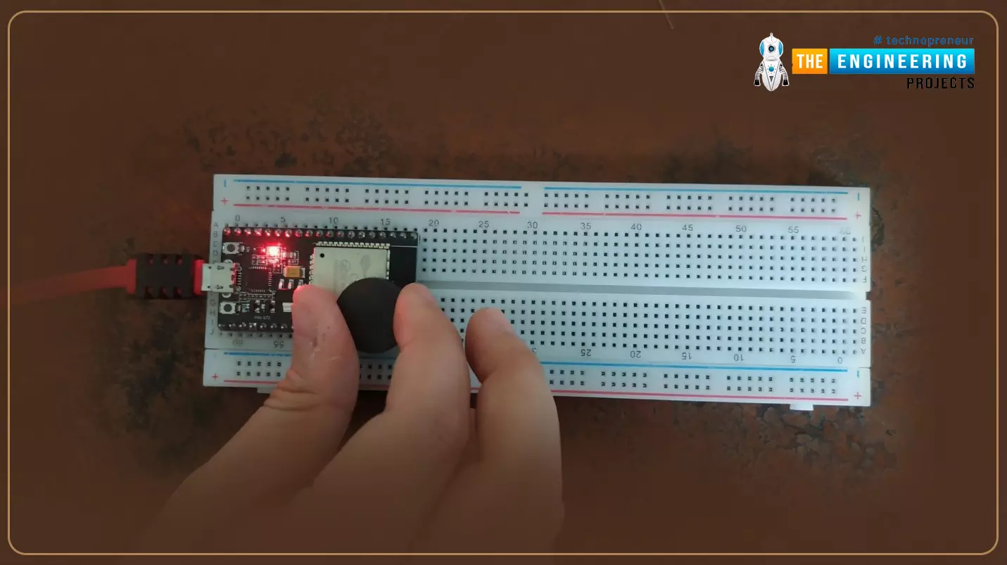
Hello readers, hope you all are doing great. In this tutorial, we are going to discuss a mechanism that allows users to update the ESP32 with a new program wirelessly or over the air (without using a USB cable to upload a new program).

Where To Buy?
No.ComponentsDistributorLink To Buy
1ESP32AmazonBuy Now

Over-The-Air (OTA) programming

Fig. 1 ESP32 OTA

  • OTA programming is the mean by which a product manufacturer or product service provider can update the features or functionality of the device wirelessly or over the air, after the device has been deployed in the field where connecting a cable or uploading the code serially is difficult.
  • One key advantage of OTA is that a single central node can send an update to multiple ESPs on the same network.
  • The device must have a provisioning client capable of receiving, processing, and setting parameters in order to receive, process, and set parameters in a mobile device over the air.

Applications of OTA programming

Mobile Phones:

  • In order to improve the compatibility with hardware and enhance the stability of software and applications, software updates are required.
  • OTA updates are intended to improve the underlying operating system, time zone rules, read-only apps installed on the system partition these updates have no effect on user-installed applications.

IoT (internet of things) application:

  • The ability to wirelessly download an application, configuration, or firmware to internet-enabled devices, also known as IoT, is referred to as over-the-air (OTA). It works in the same way that our computers, laptops, tablets, and phones do.
  • Application, where sensor nodes are frequently placed in remote or difficult-to-reach locations OTA programming can be used.

Fig. 2 OTA programming for IoT


How does OTA programming work?

There are two methods of OTA implementation.

  • Basic OTA: In the basic OTA method the program is updated into ESP32 over the air using Arduino IDE.
  • OTA web updater: In web updater OTA the program is updated over the air using a web browser.

Implementing OTA Update feature using ESP32

In this tutorial, we will discuss only the basic OTA method using Arduino IDE and ESP32 module.

If you want to know more about the basics of ESP32 and how to get started with Arduino IDE, then follow the tutorial Introduction to ESP32 Programming Series.

  • For Basic OTA programming with ESP32, it is required to install the python 2.7.x version in your system.
  • Follow the link to download python: https://www.python.org/downloads/
  • Install the python into your system.
  • Upload the basic OTA code into ESP32 using the serial port.
  • Upload the new ESP32 test code over the air using the network port into esp32 module.

To implement the Basic OTA method, an example is available is Arduino IDE.

  • You can find the code through File> Examples> ArduinoOTA> BasicOTA.
  • An image has been attached below for reference:

Fig. 3

Arduino IDE Code

  • It is required to first upload the basic OTA code serially (using serial com port).
  • Because in default mode the ESP32 is not ready for OTA updates (as there is no inbuilt OTA firmware available inside the ESP32 board).
  • Only after that you can access the OTA feature
#include <WiFi.h> #include <ESPmDNS.h> #include <WiFiUdp.h> #include <ArduinoOTA.h>   const char* ssid = "SSID"; const char* password = "Password";   void setup() { Serial.begin(115200); Serial.println("Booting"); WiFi.mode(WIFI_STA); WiFi.begin(ssid, password); while (WiFi.waitForConnectResult() != WL_CONNECTED) { Serial.println("Connection Failed! Rebooting..."); delay(5000); ESP.restart(); } ArduinoOTA.onStart([]() { String type; if (ArduinoOTA.getCommand() == U_FLASH) type = "sketch"; else // U_SPIFFS type = "filesystem";   // NOTE: if updating SPIFFS this would be the place to unmount SPIFFS using SPIFFS.end() Serial.println("Start updating " + type); }) .onEnd([]() { Serial.println("\nEnd"); }) .onProgress([](unsigned int progress, unsigned int total) { Serial.printf("Progress: %u%%\r", (progress / (total / 100))); }) .onError([](ota_error_t error) { Serial.printf("Error[%u]: ", error); if (error == OTA_AUTH_ERROR) Serial.println("Auth Failed"); else if (error == OTA_BEGIN_ERROR) Serial.println("Begin Failed"); else if (error == OTA_CONNECT_ERROR) Serial.println("Connect Failed"); else if (error == OTA_RECEIVE_ERROR) Serial.println("Receive Failed"); else if (error == OTA_END_ERROR) Serial.println("End Failed"); }); ArduinoOTA.begin(); Serial.println("Ready"); Serial.print("IP address: "); Serial.println(WiFi.localIP()); } void loop() { ArduinoOTA.handle(); }

Code Description

  • The first step is to add all the necessary header files. Here we are using four header files.
  • WiFi.h: This header file allows the ESP32 board to connect to the internet. It can serve either as a server or a client.
  • ESPmDNS.h: This library is used to implement multicast DNS query support for the ESP32 chip. A multicast UDP service is used to provide local network service.
  • WiFiUdp.h: This is a library for Arduino wifi shield. It is used to send data to a UDP host over a wireless network.
  • ArduinoOTA.h: this library allows users to update the code in the ESP32 board using wifi instead of using the serial port.
  • Next, you need to add your wifi credentials. Enter the SSID and password.

Arduino Setup() Function

  • Inside the setup () function, the first task is to begin the serial monitor at a 115200 baud rate so that, you can print the results and other required details on the serial monitor for verification purposes.
  • Set ESP32 Wi-Fi module in station mode(esp32 will act as a client device) using WiFi.mode() function.
  • Enable ESP32’s Wi-Fi module using WiFi.begin() function which is using SSID and password as arguments.
  • Wait until the ESP32 is not connected with the wifi network.
  • ESP.restart() function will reset the ESP32. ESP.restart() function tells SDK to reboot.
  • If an error occurred in OTA programming, print the error on the serial monitor

  • ArduinoOTA.begin() function is used to initialize the OTA updater.
  • Wi-Fi.lockIP() is used to fetch the IP address.
  • Print the IP address on the serial monitor.

Arduino Loop() Function

  • Inside the loop() function, ArduinoOTA.handle() function is used for updating the ESP32 code over the air using the network port instead of the serial port.
  • Compile the code and upload serially using serial com port.
  • Open the serial monitor, set the baud rate to 115200.
  • You can see the IP address on the serial monitor once the ESP32 is connected to the Wi-Fi network.

Fig. 11 Serial monitor

Uploading new program into ESP32 module Over the Air

Code

#include <WiFi.h> #include <ESPmDNS.h> #include <WiFiUdp.h> #include <ArduinoOTA.h>   const char* ssid = "public"; const char* password = "ESP32@123";   //variabls for blinking an LED with Millis const int led = 2; // ESP32 Pin to which onboard LED is connected unsigned long previousMillis = 0; // will store last time LED was updated const long interval = 1000; // interval at which to blink (milliseconds) int ledState = LOW; // ledState used to set the LED   void setup() {   pinMode(led, OUTPUT);   Serial.begin(115200); Serial.println("Booting"); WiFi.mode(WIFI_STA); WiFi.begin(ssid, password); while (WiFi.waitForConnectResult() != WL_CONNECTED) { Serial.println("Connection Failed! Rebooting..."); delay(5000); ESP.restart(); } ArduinoOTA .onStart([]() { String type; if (ArduinoOTA.getCommand() == U_FLASH) type = "sketch"; else // U_SPIFFS type = "filesystem";   // NOTE: if updating SPIFFS this would be the place to unmount SPIFFS using SPIFFS.end() Serial.println("Start updating " + type); }) .onEnd([]() { Serial.println("\nEnd"); }) .onProgress([](unsigned int progress, unsigned int total) { Serial.printf("Progress: %u%%\r", (progress / (total / 100))); }) .onError([](ota_error_t error) { Serial.printf("Error[%u]: ", error); if (error == OTA_AUTH_ERROR) Serial.println("Auth Failed"); else if (error == OTA_BEGIN_ERROR) Serial.println("Begin Failed"); else if (error == OTA_CONNECT_ERROR) Serial.println("Connect Failed"); else if (error == OTA_RECEIVE_ERROR) Serial.println("Receive Failed"); else if (error == OTA_END_ERROR) Serial.println("End Failed"); });   ArduinoOTA.begin();   Serial.println("Ready"); Serial.print("IP address: "); Serial.println(WiFi.localIP()); }   void loop() { ArduinoOTA.handle();   //loop to blink without delay unsigned long currentMillis = millis(); if (currentMillis - previousMillis >= interval) { // save the last time you blinked the LED previousMillis = currentMillis; // if the LED is off turn it on and vice-versa: ledState = not(ledState); // set the LED with the ledState of the variable: digitalWrite(led, ledState); } }
  • In the test code, which we are going to upload using a wireless network port over the air, a LED blinking function is added just to test whether the OTA functionality is working fine or not.

Note: It is required to upload the OTA programming handler code every time you upload a new code into ESP32 over the air. So that, OTA programming remains enabled for future use.

Code Description

  • Add the required header files.

  • Enter Wi-FI credentials over which you are going to upload the code wirelessly.
  • Define the GPIO pin to which LED is connected.
  • GPIO 2 is connected to the inbuilt LED.
  • To add delay, we are using timers instead of delay() function.
  • The variable interval is defining the time delay.
  • Set LED’s state to low.

Arduino Setup() Function

  • Although in the example code serial monitor is initialized but it is not required anymore as we are using the network port for communication.
  • Initialize ESP32 Wi-Fi in station mode using WiFi.mode() function.
  • Wait until esp32 is connected to the Wi-Fi network.

  • ArduinoOTA.begin() function is used to initialize the OTA updater.
  • Wi-Fi.lockIP() is used to fetch the IP address.
  • Print the IP address on the serial monitor.

Arduino Loop() Function

  • Blink the LED after every 1000ms or 1sec delay as defined in variable ‘interval’.

  • Compile the above code.
  • Go to the Tools menu, then click on port and select the network port as shown in the image below.

This concludes the tutorial. I hope you found this helpful. In the next tutorial, we will discuss the OTA web updater in ESP32.

Accident Detection System using Arduino

Hello everyone, Welcome to our new project. Our new project plays a very important role in our daily life as it is directly connected to our lives. In this project, we are going to design an Accident Detection module. Accidents are the most common thing we hear about in the news, and in social media. Everyone here or there has seen accidents or has been with one. So when any such incidents happen, we inform respective stations or hospitals in that emergency situation. But what about the accidents that happen at night, or in places where there is very less crowd or you are alone. So, to address this issue and provide a potential solution for that, we are going to learn how to detect an accident automatically and inform nearby aid/help stations.

We can use this useful project for an engineering project’s showcase for electronics, electrical engineering students, and can be used in real-life situations where it can help people in disastrous situations.

According to WHO, research says that in the current scenario, 1.3 million people are the victims of road traffic crashes, and 40% of these accidents of all fatal accidents occur at night. In most cases, the accidents are not reported immediately, or the injured doesn’t receive any help during that time. The time between the accident and the arrival of medical help for the injured can sometimes make the difference between his life or death. In the future, we can interface with the vehicle airbag system. This will optimize the proposed technology to the maximum extent and result in the finest accident detection system possible. In this Modern era, everything is being automated and with this project, we are going to automate this process with some electronic components and Arduino. So Let’s dive in. Here's the video demonstration of this project:

Where To Buy?
No.ComponentsDistributorLink To Buy
1NEO-6MAmazonBuy Now
2SIM900AmazonBuy Now
3Arduino UnoAmazonBuy Now

Software to Install:

Instead of using real components, we will design this project using Proteus Simulation. Working with simulation before attempting to make it with real components is also a smart practice. We can figure out the issue that may arise while working on real components and avoid any kind of damage to our components by simulating it.

Proteus is a very fascinating tool that allows us to simulate and create electronic circuits. Despite the fact that Proteus software contains a large library of electronics components, it still lacks pre-installed modules such as Arduino boards, GPS or GSM modules, and so on.

Let’s install the required libraries which, we are going to use in this project:

You can download this whole project for example Proteus Simulation and Arduino Code, by tapping the below button

Accident Detection System using Arduino

Project Overview:

These are required components for Accident Detection, which are as follows:

  • Arduino Uno: Arduino Uno is a development board from the Arduino family, which is the main component of this project. The Microcontroller i.e., Arduino is responsible for the decisions that are going to be processed in the project.
  • Accelerometer: An accelerometer is a device that measures acceleration, which is the change in speed (velocity) per unit time. By measuring acceleration we can get information like object inclination and vibration which helps in detecting unusual activities/ accidents.
  • GSM: A GSM/GPRS Module is a device that is actually responsible for the wireless communication with the GSM Network, in this case, it is responsible for sending the appropriate information to rescue stations.

Components Needed:

  1. Arduino Uno
  2. GPRS Module
  3. Accelerometer
  4. GSM Module
  5. Bread Board
  6. Jumper Wires

Component details:

Arduino Uno:

  • The Arduino UNO is one of the Arduino family's programmable, open-source microcontroller boards.
  • It includes an Atmel Microchip ATMega328P microcontroller with an 8-bit RISC processing core and 32 KB flash memory from Atmel.
  • It has 14 digital I/O pins, including 6 PWM pins and 6 analog I/O pins with a resolution of 10 bits (0-1024).
  • It comes with one hardware UART, one I2C, and one SPI peripheral.
  • We can use the Arduino UNO with a voltage range of 7-12 volts, but not more than 9 volts is recommended because it may damage the Arduino board
  • To power the Arduino UNO we can use a USB-B cable (the same cable that we use to upload the sketch to Arduino UNO), a DC power jack, or the Vin pin on the board.

GPS Module:

  • The Global Positioning System (GPS) is a space-based global navigation satellite system that gives accurate location and timing in all weather and at all times around the world.
  • It sendLongitude, latitude, height, and time are the four variables that a GPS receiver determines.
  • Data determined by the module will be sent to the microcontroller (Arduino Uno) through the UART protocol.
  • With a USB interface, the GPS module is simple to operate. It operates on a 3.2 to 5V supply range, allowing it to interface with both 3.3V and 5V microcontrollers.
  • It has a default baud rate of 9600 and can be modified as per our requirement.
  • We have used this to get the current location of the user.

Accelerometer:

  • Accelerometer sensors are integrated circuits (ICs) that are used to measure acceleration, inclination, and various parameters regarding the x,y,z axes. It is the main component to detect the accident.
  • Here we used the MEMS (Microelectromechanical Systems) accelerometer. These types of accelerometers are used where we have to measure the vibration or shock without any fixed reference.
  • It monitors changes in the capacitance and converts that value to analog output voltage.
  • Gyro Range of the Accelerometer sensor is ± 250, 500, 1000, 2000 °/s (may vary depending upon the sensor).
  • Accelerometer Range of the sensor module is ± 2 ± 4 ± 8 ± 16 g (may vary depending upon the sensor).

GSM module:

  • This module is used to send the notification to the rescue station or the emergency numbers.
  • It communicates with the Arduino UNO using the UART protocol.
  • It works in a voltage range of 3.5 - 5 volts.
  • There are different types of GSM modules available but in this project, we have used the SIM900D module.
  • We operate them using the AT commands. As there are hundreds of AT commands but we will use some basic only just to send the message.

Proteus Simulation of Accident Detection Circuit:

Now, it is time to start designing the main circuit of Accident detection in Proteus Simulation software.

  • Most importantly, ensure that Proteus is installed on your PC/Laptop and download all the required libraries for Proteus ahead of starting the designing steps.
  • For this project, we are going to use libraries for Arduino Uno, GPRS Module, GSM module.
  • To add the libraries in the Proteus suite we have to go to the C drive then LabCenter Electronics >> Proteus 8 professional >> Data >> Library and paste the downloaded library files here.
  • The download links of all the libraries have been provided to you in the above sections, please go check them out.
  • Let’s start the making of a new project, open the new project in Proteus.
  • After that enter the name of your new project.
  • Now our working area will be open here we will import all the required components which we are going to use.
  • The following components need to be selected from the Proteus component library. We’ll connect the components and make the circuit complete.
  • Now we have imported all the required components for this project, after this, we will start connecting them.

Circuit Diagram and Working:

  • There are two modules GPRS and GSM modules, both communicate using the UART protocol but in the Arduino UNO there is only one hardware UART’s provision. Now, you may have doubts about how we are going to connect them. No worries, we will handle that on the coding side by declaring the different pins as UART pins.
  • We can use different pins for UART using the SoftSerial library of Arduino, which will be discussed in the code.
  • We will use the digital pins for UART connections, digital pins 2 and 3 for communication of the GSM module, which means connecting the Rx and Tx of the GSM module with the D2 and D3 pins of Arduino UNO respectively.
  • Connect the Rx and Tx of the GPRS module with the D10 and D11 pins of Arduino UNO respectively.
  • As modules are connected, now we will connect the accelerometer. As it will not be possible to simulate the accelerometer in Proteus so we have used the potentiometers to change the value of the X-axis, Y-axis and Z-axis.
  • You may have doubts about how we can replace the accelerometer with potentiometers. As we will use the MEMS accelerometer, which sends the analog voltages for each axis, so we can simulate that using the potentiometer because we will receive the same type of data.
  • We need three potentiometers, one for each axis. Potentiometers of the X-axis, Y-axis and Z-axis will be connected to A1, A2 and A3 pins of Arduino respectively.
  • We will connect a serial terminal for debugging purposes.

Arduino code for Accident Detection System

Before going to start the coding, it would be easy if you understood the circuit diagram connections.

  • When we start writing the code(called a sketch in Arduino IDE), we will first include all of the necessary libraries for this project.
  • So, if the essential libraries aren't already installed in the Arduino IDE, our first step would be to get them.
  • Here we use mainly two libraries, one for serial communication and parsing data from the GPS module.
  • By heading to 'Sketch > Include Library > Manage Library' in the Arduino IDE, we can install libraries related to Arduino. We can now search for our essential libraries in the library manager. We can also use zip files to install the libraries.
  • As we've installed all the specified libraries. Let’s include them in our sketch.
  • Now, we are declaring D2 and D3 pins for serial communication with GPRS modules and declaring GPS objects as well, which will pretty much do all the grunt work with the NMEA data.
  • After that, we will declare variables to store the GPS module data.
  • Now, we are declaring pins and variables for the accelerometer which we will use in our project. Here, we are using Analog Pins because we are reading the analog voltages from the potentiometer.
  • We need to declare two threshold values for change in acceleration when an accident is detected.
  • The min and max values can vary. So, it is highly recommended to measure the values by accelerometer for devices using.

Void Setup():

  • It is one of the most important functions which will execute only once in the whole process.
  • As we are using a GPS module in our project, We should first start serial communication between the components and Monitor them through “Serial Monitor” in the Arduino IDE.
  • “Serial.begin” is used to set up the serial configuration for the device which is connected to the Serial Port of the Arduino. Here, we will set the baud rate for that device i.e 9600 in our case.
  • “serial_connection.begin(9600)” is used to set up the UART configuration for the GPS module. As the GPS module communicates to the Arduino at the baud rate of 9600.
  • We are using an Accelerometer in the circuit and it was clearly explained in detail that it will sense the x,y,z coordinates of the device and send them to Arduino.
  • Here, we have initialized a for loop to collect the sample data for x, y, and z coordinates of the device in the ideal state.
  • Afterward, the sample coordinates have been successfully measured by the Accelerometer sensor, but we need an average value for smoothing the sample coordinate values. So here, we will calculate the average of each coordinate and print them in the serial monitor.
  • After the setup, we will write our main application code in the Void loop function.

Void loop():

  • It is the second most important function of Arduino code. It will come to action after the execution of “void setup()”
  • We'll write the code required to run in a continuous loop in this part. So this is where we'll write our primary application code.
  • As a result, when the code gets to the void loop portion, We firstly take the NMEA data from the GPS module and print it in the serial monitor.
  • Wait a minute, NMEA??, I can understand all the questions in your mind. Let us give you a simple explanation regarding NMEA and its applications.
  • The word NMEA stands for the National Marine Electronics Association, which is a mode of communication that existed before inventing GPS. NMEA-format GPS data can be accessed with a wide variety of GPS receivers, instead of creating a new custom interface every time. Thus, it makes our lives easier using the GPS Module.
  • When we are printing the NMEA data into the serial monitor, it will be printed in a specific structure. This NMEA data was output from a GPS receiver:

“$GPGGA,191605.00,4521.7785210,N,07331.7656561,W,2,19,1.00,674.354,M,19.900,M,0.90,0000*60”

  • All NMEA signals start with the ‘ $ ’ character and for every data field such as coordinates, and various parameters are separated by a comma. The data further includes Timestamp, Latitude, Longitude, Quality indicator, Number of satellites involved, Altitude, etc., which is not necessary to remember. Make sure to get the data from the GPS module. If we have succeeded in this step and get the data on the serial monitor, then we are good to go for further processing.
  • The “if” statement is to process the NMEA data and separate the data into the required format if there is any location updated to the GPS receiver.
  • As we have already received NMEA data in the previous step, the data will be separated into Latitude, Longitude and Altitude.
  • In the Loop function, the values of GPS and accelerometer will be continuously tracked.
  • Here, the analog values of x,y,z coordinates are being measured and printed in the serial monitor.
  • These are not the values we measured in the void setup, those were the values to take the readings in the ideal state of the device.
  • But in the loop, the values are the present x,y and z coordinates measured by the accelerometer.
  • This is the condition for accident detection, we have already discussed before that in the void loop the x,y,z coordinate values are continuously extracted and the “if” statement here compares the recent values with fixed min and max values of the coordinates.
  • If the recent values are indistinct or do not match with threshold values i.e., max value and min value, then it indicates that an accident has been detected.
  • When the accident detection condition is satisfied, the GPRS module will be activated and will call to rescue stations for aid/help and their home.
  • Here, we have programmed to give a call 5 times to the appropriate numbers in the “for” loop.
  • And the process also includes a messaging feature along with calling to rescue stations.
  • When the same accident condition is satisfied, the messaging feature will be activated and we are going to send the alerting message including the Location, Latitude, Longitude, and Google map location link by appending latitude and longitude values the to respective numbers.

Results / Working:

We have successfully completed our Accident detection project and it’s ready to test!
  • Before going to start the simulation, we need to import the hex files of Arduino code in the Proteus, to do so click on the Arduino and browse to the hex file of the code and select.
  • Now we need to add the program files for the GPS and GPRS modules.
  • Here we should note that we only need to upload the program files for the modules while we are working in simulation. In the real modules, they come up with pre-installed codes.

Now we have done all the prerequisites of simulation.

  • Let’s power the circuit and start the simulation, firstly the void setup function will run and it will initialize all the required pins and variables and will read the ideal state values of the potentiometer.
  • Now to simulate the accident case, we will change the values from the potentiometer, so when the potentiometer’s value changes and the falls in the Min and Max value range the if condition will be stratified.
  • After this GSM module will call the stored number 5 times and send the GPS location with Google maps link in that.
  • We have used some serial monitors for debug purposes, you can see the current state of the project using them.

I hope you have a good understanding of how our Accident Detection project works and that you have liked it. Although I believe we have covered almost everything, please let us know if you have any questions or suggestions in the comments section.

Thank you very much for reading this project. All the best for your projects!

ESP32 Low Power Modes

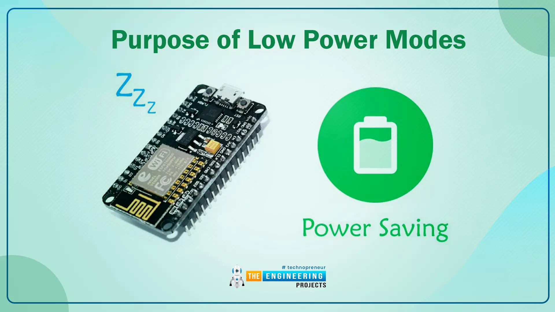
Hello readers, hope you all are doing great. In this tutorial, we will discuss low power modes in ESP32, their purpose and their implementation to increase the battery life by reducing power consumption.

Where To Buy?
No.ComponentsDistributorLink To Buy
1ESP32AmazonBuy Now

Purpose of Low Power Modes

Fig.1

Along with multiple wireless and processing features, ESP32 also provides us with a power-saving feature by offering sleep modes. When you are powering the ESP32 module from the live supply using an adaptor or a USB cable, there is nothing to worry about power consumption. But when you are using a battery, as a power source to ESP32, you need to manage the power consumption for longer battery life.

Low Power Modes in ESP32

When ESP32 is in sleep mode, a small amount of power is required to maintain the state of ESP32 in RAM (random access memory) and retain necessary data. Meanwhile, the power supply won’t be consumed by any unnecessary peripheral or inbuilt modules like Wi-Fi and Bluetooth.

ESP32 offers 5 power modes. Each mode is configurable and offers different power-saving capabilities:

  1. Active Mode
  2. Modem Sleep Mode
  3. Light Sleep Mode
  4. Deep Sleep Mode
  5. Hibernation Mode

Fig. 2

Active Mode:

  • In active mode, all the modules and features of ESP32, like processing cores, Wi-Fi, Bluetooth, radio etc. remain active all the time.
  • Most of the power consumption occurs in this power mode which can vary between 160 -240mA and sometimes the maximum consumption could reach up to 790mA (when both Wi-Fi and Bluetooth are enabled or active at the same time).

Modem Sleep Mode:

  • In this mode, radio, Wi-Fi, Bluetooth will be disabled and everything else will remain active. Power consumption in this mode varies from 3 to 20mA.
  • Sleep modes can switch between modem and active modes as per the predefined intervals, by following the associated sleep pattern.

Light Sleep Mode:

  • During this mode, the central processing unit is paused by turning/powering off its clock.
  • ULP- coprocessor and RTC (real-time clock) remain active during light sleep mode and power consumption is 0.8mA.

Deep Sleep mode:

  • In this mode, the Ultra Low Power (ULP) coprocessor remains active while the ESP32 core and other digital peripherals remain inactive.
  • The ULP coprocessor wakes up the core processor when required.
  • The amount of power consumed in this mode is 10uA.

Fig 3

Hibernation Mode:

    • In this mode, the ULP coprocessor and internal oscillator both are disabled.
  • Only a real-time clock (RTC) remains active to wake up the processor and other required modules from hibernation mode and the power consumption in this mode is extremely low that is approximately 2.5uA.

For a better understanding of low power modes in ESP32, we are going to implement deep sleep mode in esp32 and will also discuss how to wake up the device from deep sleep mode.

Deep Sleep mode and Wakeup Using Capacitive Touch-sensitive pins

To implement deep sleep modes we are going to use another ESP32 feature that is Capacitive Touch Sensing pins. These pins can sense the presence of a body that holds an electric charge.

So we are going to use these touch-sensitive pins for waking up ESP32 from deep sleep mode using the Arduino IDE compiler.

In Arduino IDE examples are given for deep sleep mode with various wake-up methods.

  • Follow the image attached below to open the example code:

Fig. 4 Example code.

  • Arduino IDE Code

#define Threshold 40 /* Greater the value, more the sensitivity */ RTC_DATA_ATTR int bootCount = 0; touch_pad_t touchPin; /* Method to print the reason by which ESP32 has been awaken from sleep */ void print_wakeup_reason(){ esp_sleep_wakeup_cause_t wakeup_reason;   wakeup_reason = esp_sleep_get_wakeup_cause();   switch(wakeup_reason) { case ESP_SLEEP_WAKEUP_EXT0 : Serial.println("Wakeup caused by external signal using RTC_IO"); break; case ESP_SLEEP_WAKEUP_EXT1 : Serial.println("Wakeup caused by external signal using RTC_CNTL"); break; case ESP_SLEEP_WAKEUP_TIMER : Serial.println("Wakeup caused by timer"); break; case ESP_SLEEP_WAKEUP_TOUCHPAD : Serial.println("Wakeup caused by touchpad"); break; case ESP_SLEEP_WAKEUP_ULP : Serial.println("Wakeup caused by ULP program"); break; default : Serial.printf("Wakeup was not caused by deep sleep: %d\n",wakeup_reason); break; } }   /* Method to print the touchpad by which ESP32 has been awaken from sleep */ void print_wakeup_touchpad(){ touchPin = esp_sleep_get_touchpad_wakeup_status();   switch(touchPin) { case 0 : Serial.println("Touch detected on GPIO 4"); break; case 1 : Serial.println("Touch detected on GPIO 0"); break; case 2 : Serial.println("Touch detected on GPIO 2"); break; case 3 : Serial.println("Touch detected on GPIO 15"); break; case 4 : Serial.println("Touch detected on GPIO 13"); break; case 5 : Serial.println("Touch detected on GPIO 12"); break; case 6 : Serial.println("Touch detected on GPIO 14"); break; case 7 : Serial.println("Touch detected on GPIO 27"); break; case 8 : Serial.println("Touch detected on GPIO 33"); break; case 9 : Serial.println("Touch detected on GPIO 32"); break; default : Serial.println("Wakeup not by touchpad"); break; } }   void callback(){ //placeholder callback function }   void setup(){ Serial.begin(115200); delay(1000); //Take some time to open up the Serial Monitor   //Increment boot number and print it every reboot ++bootCount; Serial.println("Boot number: " + String(bootCount));   //Print the wakeup reason for ESP32 and touchpad too print_wakeup_reason(); print_wakeup_touchpad();   //Setup interrupt on Touch Pad 3 (GPIO15) touchAttachInterrupt(T3, callback, Threshold);   //Configure Touchpad as wakeup source esp_sleep_enable_touchpad_wakeup();   //Go to sleep now Serial.println("Going to sleep now"); esp_deep_sleep_start(); Serial.println("This will never be printed"); }   void loop(){ //This will never be reached }

Code Description

  • The first step is to set the threshold value for touch-sensitive pins.
  • When a body, containing an electric charge touches a touch-sensitive pin, the threshold value decreases below 40, that decrease in the threshold value will make ESP32 wake up from deep sleep mode. In the example code threshold value is 40.
  • The next task is to store the data into RTC memory (using RTC_DATA_ATTR ) because in deep sleep mode only RTC remains active and all other peripherals, processors, wireless modules will be disabled.
  • ESP32 offers 8kB SRAM on RTC to store the data.
  • But when you press EN/reset button the data stored in RTC memory will also be erased.
  • bootCount an integer type variable is used to count the number of times ESP32 has woken up during sleep mode. The value of bootCount variable is stored in RTC memory.
  • The print_wakeup_reason() function is used to print the reason for ESP32 wakeup from deep sleep whether it is due to an external interrupt, timer, or touch-sensitive pins.
  • The ESP32 has multiple capacitive touch-sensitive GPIO pins which can be used to wake up esp32 from deep sleep mode.
  • Print_wakeup_touchpad() function is used to print the GPIO pin which made ESP32 wake up from sleep mode.
  • When you hold a capacitive sensitive pin for a longer duration the threshold value (initialized globally) decreases from its predefines value i.e., 40 which will cause ESP32 to wake up, at that time the callback() function comes into action.
  • This function will be used as an argument inside the touchAttachInterrupt() function.

Setup()

  • Inside the setup() function the first task is to start the serial monitor with a baud rate of 115200.
  • Next, if there is any increment in boot count due to wake up calls, then print that count on the serial monitor.

Call the respective functions to print the wake-up reason:
  • Print_wakeup_reason() is used to print whether the ESP32 wake-up is caused by an external interrupt, timer or a capacitive sensitive pin.
  • If the wake up is due to a capacitive sensitive pin then the print_wakeup_touchpad() function will print the GPIO pin number which caused the wake-up.
  • The next task is to attach the interrupt using touchAttachInterrupt() function, to capacitive sensitive GPIO pin which you will use to wake up ESP32.
  • In this example we are using GPIO 15 capacitive sensitive pin as a wakeup interrupt pin.
  • esp_sleep_enable_touchpad_wakeup() is used to enable touch sensor feature.
  • esp_deep_sleep_start() function is used to make ESP32 enter to deep sleep mode.
  • Once ESP32 enters the sleep mode no other operation or data communication is possible until it receives a wakeup call.

Fig 12

Loop()

  • In this example code, there is nothing, written inside the loop function. But you can change the code as per your requirements.

Code Testing

  • To test the code, use a connecting wire (male to female) and connect one side to ESP32’s touch-sensitive pin (which you have mentioned in the code as an interrupt).
  • When you touch that pin an interrupt will be generated to wake ESP32 from sleep.
  • You can see the results on a serial monitor or can check the current consumption or can run other functions once it is awake like blinking LED.
  • In this code, we are using GPIO_15 touch-sensitive pin.

Fig. 13 waking up esp32 using capacitive sensitive GPIO pin

We have attached a screenshot from the serial monitor for reference.

Fig. 14

Deep Sleep mode and Wakeup Using Interrupt method

Arduino IDE Code

#define uS_TO_S_FACTOR 1000000ULL /* Conversion factor for micro seconds to seconds */ #define TIME_TO_SLEEP 5 /* Time ESP32 will go to sleep (in seconds) */ RTC_DATA_ATTR int bootCount = 0; /* Method to print the reason by which ESP32 has been awaken from sleep */ void print_wakeup_reason(){ esp_sleep_wakeup_cause_t wakeup_reason; wakeup_reason = esp_sleep_get_wakeup_cause(); switch(wakeup_reason) { case ESP_SLEEP_WAKEUP_EXT0 : Serial.println("Wakeup caused by external signal using RTC_IO"); break; case ESP_SLEEP_WAKEUP_EXT1 : Serial.println("Wakeup caused by external signal using RTC_CNTL"); break; case ESP_SLEEP_WAKEUP_TIMER : Serial.println("Wakeup caused by timer"); break; case ESP_SLEEP_WAKEUP_TOUCHPAD : Serial.println("Wakeup caused by touchpad"); break; case ESP_SLEEP_WAKEUP_ULP : Serial.println("Wakeup caused by ULP program"); break; default : Serial.printf("Wakeup was not caused by deep sleep: %d\n",wakeup_reason); break; } }   void setup(){ Serial.begin(115200); delay(1000); //Take some time to open up the Serial Monitor   //Increment boot number and print it every reboot ++bootCount; Serial.println("Boot number: " + String(bootCount));   //Print the wakeup reason for ESP32 print_wakeup_reason();   /* First we configure the wake up source We set our ESP32 to wake up every 5 seconds */ esp_sleep_enable_timer_wakeup(TIME_TO_SLEEP * uS_TO_S_FACTOR); Serial.println("Setup ESP32 to sleep for every " + String(TIME_TO_SLEEP) + " Seconds");   /* Next we decide what all peripherals to shut down/keep on By default, ESP32 will automatically power down the peripherals not needed by the wakeup source, but if you want to be a poweruser this is for you. Read in detail at the API docs http://esp-idf.readthedocs.io/en/latest/api-reference/system/deep_sleep.html Left the line commented as an example of how to configure peripherals. The line below turns off all RTC peripherals in deep sleep. */ //esp_deep_sleep_pd_config(ESP_PD_DOMAIN_RTC_PERIPH, ESP_PD_OPTION_OFF); //Serial.println("Configured all RTC Peripherals to be powered down in sleep");   /* Now that we have setup a wake cause and if needed setup the peripherals state in deep sleep, we can now start going to deep sleep. In the case that no wake up sources were provided but deep sleep was started, it will sleep forever unless hardware reset occurs. */ Serial.println("Going to sleep now"); Serial.flush(); esp_deep_sleep_start(); Serial.println("This will never be printed"); }   void loop(){ //This is not going to be called }

Code Description

  • The first task is, to define the timer period for which ESP32 will be in deep sleep mode.
  • As we know that ESP32 operates at the MHz frequency range so the timer will be in microseconds. So, it is required to convert the time into seconds.
  • To add a timer of 5sec we need to multiply 5*1000000.
  • bootCount an integer type variable is used to count the number of times ESP32 has woken up during sleep mode. The value of bootCount variable is stored in RTC memory.

Fig 15

  • The print_wakeup_reason() function is used to print the reason for ESP32 wakeup from deep sleep whether it is due to an external interrupt, timer or touch-sensitive pins.

Fig. 16

Setup()

  • As discussed earlier, inside the setup function first we need to initialize the serial monitor at 115200 baud rate and then print the value of bootCount variable which is incrementing every time a wakeup interrupt occurs.

Fig. 17

  • The esp_sleep_enable_wakeup() function is used to enable the timer to generate a timer interrupt by passing time in microsecond as an argument.
  • In the beginning of code we have defined some global variable to add 5 sec timer (or 5000000us) and after every 5 sec ESP32 should wake up from deep sleep till 5 sec.

Fig. 18

  • esp_deep_sleep_start() function is used to make ESP32 enter the deep sleep mode.

Fig. 19

Testing

  • You can see the results of above code on serial monitor as shown is the image attached below.

Fig 20

This concludes the tutorial. I hope you found this useful, and I hope to see you soon for the new ESP32 tutorial.

ESP32 PWM(Pulse Width Modulation) in Arduino IDE

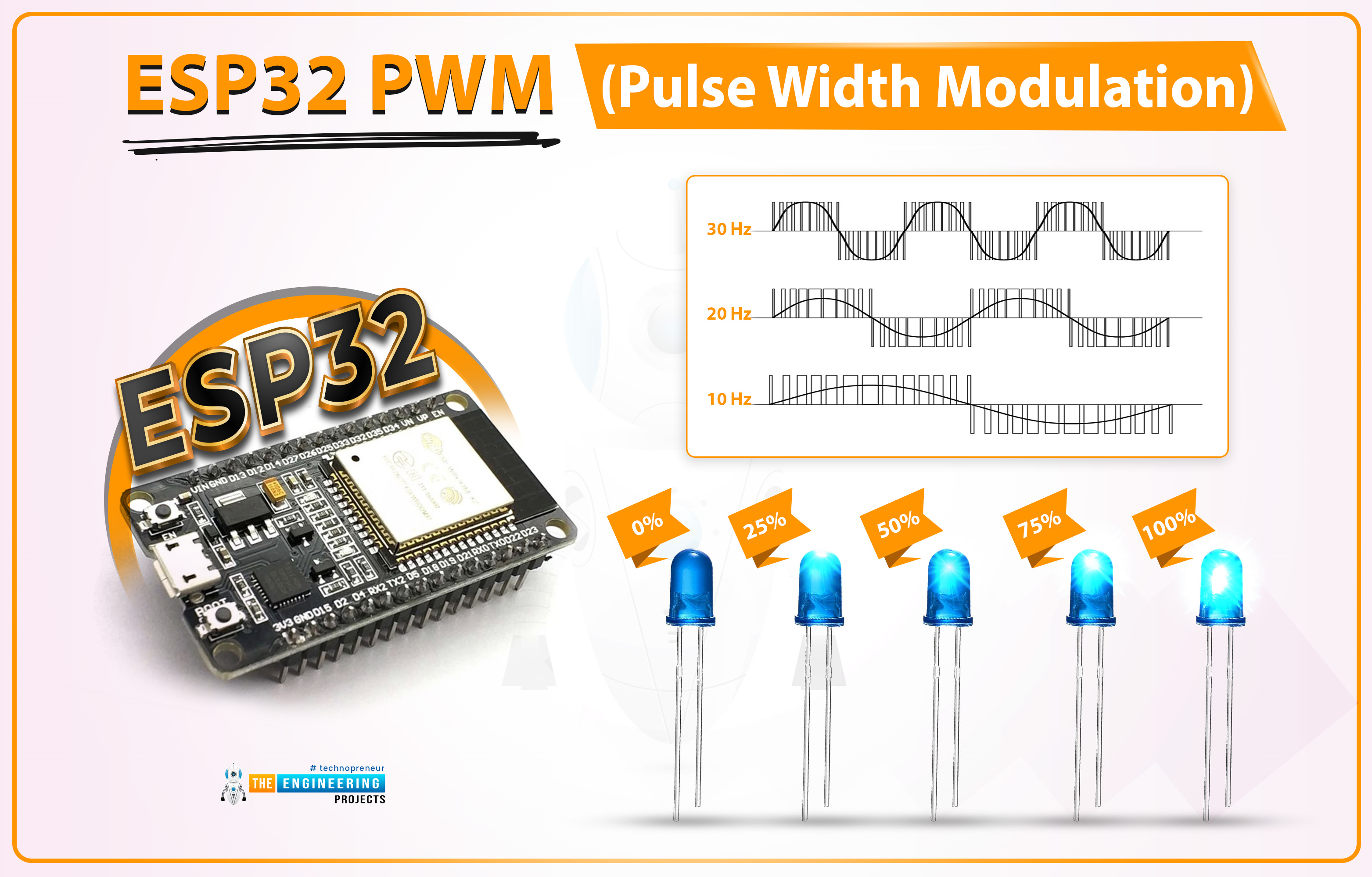
Hello readers, I hope you all are doing great. Welcome to the 3rd Lecture of Section 2 in the ESP32 Programming Series. In this tutorial, we are going to discuss another important feature of ESP32 i.e. PWM(Pulse Width Modulation).

Pulse Width Modulation is a technique to reduce the voltage by pulsating it. In today's lecture, we will first understand the basic concept of PWM, and after that will design two projects to fully grasp it. In the first project, we will control the brightness of an LED, while in the second one, we will control the speed of a DC Motor.

  • Here's the video demonstration of PWM Control in ESP32:

Before going forward, let's first have a look at the PWM working:

Where To Buy?
No.ComponentsDistributorLink To Buy
1ESP32AmazonBuy Now

What is Pulse Width Modulation?

PWM is used to control the power delivered to the load by pulsating the ON-Time of the voltage pulse, without causing any power loss. Let's understand the PWM concept with the help of below image:

  • As you can see in the above image, Figure A shows a simple 5V DC signal.
  • Figure D shows a simple circuit with a manual switch, now if we turn the switch ON & OFF manually, the Load will also behave in the same way. Its waveform is shown in Figure B, when the switch is ON, we are getting +5V and when it's OFF, output is 0V.
  • Instead of manual switching, if we place a fast automatic switching circuit (FETs, MOSFETs etc.), the output pulse won't show fluctuations, instead, it will get steady but its overall power will be reduced.
  • Let's understand the working of PWM with an example:

Suppose a DC Motor runs at 200RPM over 5V. Now, if we want to reduce its speed to 100 RPM, we need to reduce its input voltage to 2.5V(approx). So, either we can replace the 5V battery with a 2.5V Battery or use a PWM circuit to reduce the voltage level from 5V to 2.5V. In this specific case, the PWM pulse will be ON for 50% of the time and get OFF for the remaining 50% of the time.

The behavior of the PWM signal is determined by the following factors:

  • Frequency
  • Duty Cycle
  • Resolution

PWM Frequency:

  • The Frequency of a signal is defined as the number of cycles per second, denoted by "f" and the measuring unit is hertz(Hz).
  • The Frequency (f) of a signal is inversely proportional to its time period(t).
  • Let's understand the signal Frequency with the help of below image:

As you can see in the below figure, we have taken two signals for a duration of 1 second. The first signal completes 10 Cycles in 1 second, so we can say it has a frequency of 10Hz, while the second one has a frequency of 5Hz as it completes 5 cycles in 1 second. So, I hope now it's clear that the number of cycles per second is the frequency of a signal.

  • The frequency of a PWM signal depends on the provided clock source.
  • In the case of microcontrollers, the clock source is provided by the crystal oscillator. So, a 40MHz Crystal Oscillator can produce high-frequency PWM signals as compared to a 20MHz oscillator.

PWM Duty Cycle:

Duty Cycle is the ratio of ON time(when the signal is high) to the total time taken to complete the cycle. The duty cycle is represented in the form of a percentage (%) or ratio. Let's understand the PWM Duty Cycle with the help of below image:

  • The 1st graph shows no signal, so we can say it has a 0% Duty Cycle because there's no ON-Time.
  • The 2nd graph shows 5 cycles of a signal and in each cycle, the signal is ON only for 25% of the total time. So, its Duty Cycle is 25%.
  • In the 3rd graph, the signal has a duty cycle of 50% because it's HIGH for 50% of the cycle.
  • You can calculate the 4th graph, its duty cycle is 75% as it is HIGH for 75% of the total duration.
  • The last graph shows a pure DC Signal of 5V, and as it is HIGH for the whole cycle, its duty cycle will be 100%.

Resolution:

The resolution of a PWM signal defines the number of steps it can have from zero power to full power. The resolution of the PWM signal is configurable for example, the ESP32 module has a 1-16 bit resolution, which means we can configure maximum a of 65536 (2^16) steps from zero to full power.

Implementing PWM using ESP32

In the ESP WROOM-32 module, there are 16 PWM channels. All the channels are divided into two groups containing 8 channels in each group. The resolution can be programmed between 1 to 16 bits and frequency also depends upon the programmed resolution of the PWM signal.

Now

For the demonstration of PWM in ESP32 we are going to explain two examples:

  1. Controlling LED brightness using PWM
  2. Controlling DC motor speed using PWM

ESP32 Code for Controlling LED brightness using PWM

We are using Arduino IDE to compile and upload the code into the ESP WROOM-32 board.

  • If you are new to Arduino IDE and ESP32 then follow our previous tutorial, Introduction to ESP32 programming series for detailed information.
  • ESP32’s inbuilt LED is used in this code. You can also connect an external LED as per your requirements.

Arduino IDE Code:

// Global variable declaration to set PWM properties
const int ledChannel = 0; // select channel 0
const int resolution = 8; //8-bit resolutin i.e., 0-255
const int frequency = 5000; // set frequency in Hz
int dutyCycle = 0;

void setup()
{
    Serial.begin(115200);
    ledcSetup(ledChannel, frequency, resolution); // configure LED PWM functionalities
    ledcAttachPin(LED_BUILTIN, ledChannel); // attach the channel to the GPIO to be controlled
}

void loop()
{
    while(dutyCycle <200)
    {
        ledcWrite(ledChannel, dutyCycle++); // changing the LED brightness with PWM
        Serial.print(" duty Cycle ++ :");
        Serial.println(dutyCycle); // display the duty cycle on serial monitor
        delay(5);
    }
    while(dutyCycle>0)
    {
        ledcWrite(ledChannel, dutyCycle--); // changing the LED brightness with PWM
        Serial.print(" duty Cycle -- :");
        Serial.println(dutyCycle); // display the duty cycle on serial monitor
        delay(5);
    }
}

Code Description

Global Variable declaration:
  • The first step is to declare variables for setting PWM properties.
  • As we have already mentioned that ESP WROOM-32 has 16 PWM channels (0 to 15). So, the first step will be to select a PWM channel between 0-15. In the Arduino IDE code, we are using PWM channel_0 to generate a PWM signal.
  • The next step will be to choose the resolution. The maximum resolution for ESP32 is 16-bit. You can choose any value between 1-16. PWM resolution is the factor that decides the maximum duty cycle.
  • For example, if we choose 10-bit resolution then the maximum duty cycle of the output signal will be 2^10 that is 1024 (0-1023) and similarly, for 8-bit resolution the duty cycle will be 2^8=256 (0- 255).
  • 5KHz or 5000Hz is the PWM signal frequency.
  • We also need to initialize a variable to store the duty cycle value.

// Global variable declaration to set PWM properties
const int ledChannel = 0; // select channel 0
const int resolution = 8; //8-bit resolutin i.e., 0-255
const int frequency = 5000; // set frequency in Hz
int dutyCycle = 0;

Arduino Setup() Function

  • Inside setup() function we are going to start serial monitor at 115200 baud rate.

Serial.begin(115200);
  • To configure PWM properties we are calling the ledcSetup() function which uses PWM properties (like PWM channel, frequency and PWM resolution) as arguments.

ledcSetup(ledChannel, frequency, resolution); // configure LED PWM functionalities
  • ledcAttachPin() function is used to assign the LED_BUILTIN pin to the PWM channel.

ledcAttachPin(LED_BUILTIN, ledChannel); // attach the channel to the GPIO to be controlled

Arduino Loop() Function

  • Inside the loop function, we going to run a conditional control loop (while loop) to change the LED brightness along with the change in duty cycle.
  • At first, the value of the duty cycle is going to increase continuously until it reaches max 8-bit resolution ( that is 255).
  • The serial monitor will print the duty cycle value with some delay.

while(dutyCycle <200)
    {
        ledcWrite(ledChannel, dutyCycle++); // changing the LED brightness with PWM
        Serial.print(" duty Cycle ++ :");
        Serial.println(dutyCycle); // display the duty cycle on serial monitor
        delay(5);
    }

  • After increasing the duty cycle to maximum resolution another while loop is used to decrease the duty cycle to value 0 from 255 and proportionally the LED brightness and the PWM output will be printed on the serial monitor.

while(dutyCycle>0)
{
    ledcWrite(ledChannel, dutyCycle--); // changing the LED brightness with PWM
    Serial.print(" duty Cycle -- :");
    Serial.println(dutyCycle); // display the duty cycle on serial monitor
    delay(5);
}

Code Testing

  • You can see the change in the value of the duty cycle on the serial monitor. We have attached a screenshot below from the Arduino IDE serial monitor for reference.

  • For a better understanding of PWM output you can use an oscilloscope (either CRO or DSO) by connecting the PWM output pint and GND pint to the oscilloscope probe, if available.
  • You can also use a serial plotter to see the PWM output if you do not have an oscilloscope.
  • To access the serial plotter, use sort-cut key shift+ctrl+L or follow the image attached below:

Fig. 8 Arduino IDE Serial Plotter

  • We have attached a screenshot of the PWM output waveform from the serial plotter for better understanding.
  • You can vary the value of duty cycle anywhere between 0-8 bit resolution.
  • For example in the image attached below the duty cycle is 200.

Fig. 9 Serial plotter PWM output

ESP32 Code for Controlling DC motor speed using PWM

Fig. 10

In this example, we are going to implement PWM using ESP WROOM-32 to control the speed of a DC motor.

The speed of the DC motor depends upon the input power supply. So, by varying the power input we can also vary (increase or decrease) the speed of DC motor.

Hardware components required:

  • ESP WROOM-32 board
  • DC motor
  • L298N motor driver
  • Connecting wires
  • Data cable

L298N motor driver: A motor driver is used between the ESP32 board and DC motor to resolve the power compatibility issues.

Both the ESP32 board and DC motor operate at different power ratings due to which you can not connect the two devices directly. So a motor driver is used to receive a low power input from the ESP32 board and drive/run DC motor at slightly high power.

L298N can drive a DC motor that operated between 5 to 35 voltage range and maximum current of 2A.

There are various DC motor drivers available in the market for example L293D, DRV8833, MAX14870 single brushed motor driver etc. You can choose the driver of your choice depending upon the application and power ratings.

Fig. 11

FIG. 12 IC L298N pin-out

  • You can also change the direction of rotation by connecting the input as per the table drawn below:
IN_1 IN_2 Rotation
HIGH LOW DC motor rotates in a clockwise direction
LOW HIGH The motor rotates in an anti-clockwise direction
LOW LOW Motor STOP
HIGH HIGH Motor STOP

Table 1

Arduino Code

//configure GPIO pins to connect motor driver
int enable1Pin = 14;
int M_Pin1 = 26;
int M_Pin2 = 27;

// Setting PWM properties
const int freq = 10000;
const int pwmChannel = 0;
const int resolution = 8;
int dutyCycle = 150;

void setup()
{
    Serial.begin(115200);

    // sets the pins as outputs:
    pinMode(M_Pin1, OUTPUT);
    pinMode(M_Pin2, OUTPUT);
    pinMode(enable1Pin, OUTPUT);

    //Configure LED PWM functionalities
    ledcSetup(pwmChannel, freq, resolution);

    // attach the channel to the GPIO to be controlled
    ledcAttachPin(enable1Pin, pwmChannel);

    Serial.print("Testing DC Motor...");
}

void loop()
{
    // Move the DC motor in anti-clockwise direction at maximum speed
    Serial.println("Moving reverse");
    digitalWrite(M_Pin1, LOW);
    digitalWrite(M_Pin2, HIGH); 
    delay(500);

    // Move DC motor forward with increasing speed
    Serial.println("Moving Forward");
    digitalWrite(M_Pin1, HIGH);
    digitalWrite(M_Pin2, LOW);

    //----while loop----
    while (dutyCycle <= 255)
    {
        ledcWrite(pwmChannel, dutyCycle); 
        Serial.print("Speed increasing with duty cycle: ");
        Serial.println(dutyCycle);
        dutyCycle = dutyCycle +5;
        delay(100);
    }

    while (dutyCycle >150)
    {
        ledcWrite(pwmChannel, dutyCycle); 
        Serial.print("Speed decreasing with duty cycle: ");
        Serial.println(dutyCycle);
        dutyCycle = dutyCycle -5;
        delay(100);
    }

    // _____Stop the DC motor
    Serial.println("STOP DC motor");
    digitalWrite(M_Pin1, LOW);
    digitalWrite(M_Pin2, LOW);
    delay(500);
}

Code Description

  • The first step is to configure GPIOs which are to be connected with the DC motor driver (L298N).
  • Here we are using three GPIOs, the first one is connected with the Enable_A pin and the rest of the two are connected with motor inputs.
  • You can also control 2 motors with the same driver using Enable_2 and its respective input pins.

//configure GPIO pins to connect motor driver
int enable1Pin = 14;
int M_Pin1 = 26;
int M_Pin2 = 27;
  • The next step is to define variables to store PWM properties as discussed in the previous example.
  • You can vary the frequency and duty cycle of the PWM signal as per your requirements but, within the desired range.
  • Here we are assigning 10000Hz or 10KHz frequency with 8-bit resolution (0-255 duty cycle) and the initial duty cycle value is 150 for PWM channel 0.

// Setting PWM properties
const int freq = 10000;
const int pwmChannel = 0;
const int resolution = 8;
int dutyCycle = 150;

Arduino Setup() Function

  • Inside the setup function, the first task is to initialize the serial monitor with a 115200 baud rate.

Serial.begin(115200);
  • Set the operating mode of three GPIO pins (which are to be connected with motor driver board) as output.

// sets the pins as outputs:
pinMode(M_Pin1, OUTPUT);
pinMode(M_Pin2, OUTPUT);
pinMode(enable1Pin, OUTPUT);

  • Call the function ledcSetup() to configure PWM properties by passing PWM properties as arguments.

//Configure LED PWM functionalities
ledcSetup(pwmChannel, freq, resolution);
  • Next, you need to select the GPIO pin which will provide the PWM output from ESP32 to the motor driver using ledcAttachPin() function which uses the PWM output pin and PWM channel as two arguments.

// attach the channel to the GPIO to be controlled
ledcAttachPin(enable1Pin, pwmChannel);

Arduino Loop() Function

  • Start rotating the motor in the anti-clockwise direction. Follow Table 1 for more details regarding the direction of rotation.
  • Add the delay of 0.5 sec or as per your requirements.

Fig. 19

  • Rotate the DC motor in a clockwise direction by setting M_PIN1 as high ND m_Pin2 as low.

Fig. 20

  • As we have initialized the duty cycle variable with a value of 150. Now, increase the motor speed by increasing the value of the Duty cycle from 150 by increasing 5 steps continuously until it reaches the maximum value that is 255.

Fig. 21 Increasing speed

  • After reaching the maximum speed at 255 duty cycle, now let's decrease the speed of DC motor till 150 duty cycle with the decrease of 5 steps every time.

Fig. 22 Reducing speed

  • Stop duty cycle by either writing both the motor pins(M_Pin1, M_Pin2) to LOW or HIGH (like XOR gate).

Fig. 23 STOP DC motor

Code Testing

  • For a better understanding, open the serial monitor using shortcut keys ctrl+shift+M.
  • On the serial monitor, you can see the increase and decrease in duty cycle and can compare it with DC motor speed.

Fig. 24 PWM output on serial monitor

  • You can also check the PWM output on the Serial plotter by pressing the ctrl+shift+L keys.
  • It is visible through the waveform that the duty cycle is varying from 150 to 255 and reverse and proportionally the seed of the DC motor.

Fig. 25 PWM output on Serial Plotter

This concludes the tutorial. I hope you found this useful, and I hope to see you soon for the new ESP32 tutorial.

ESP32 Web Socket Server

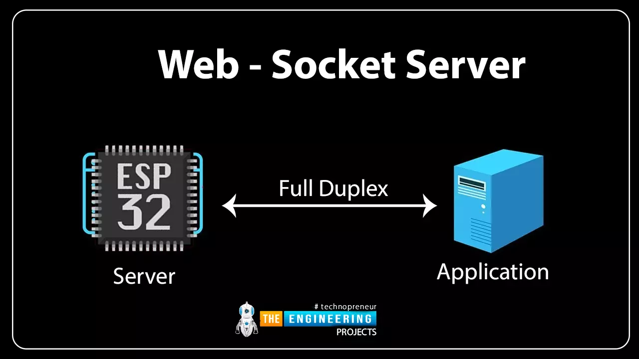
Hello readers, hope you all are doing great. In this tutorial, we will discuss another ESP32 protocol that is Web Socket and we will also explain how to create a web server using web socket protocol with ESP32. So, we will have a look at What is a web socket server, How web socket protocol is different from HTTP protocol, What is handshaking in networking, Three-way handshaking, Web socket application, Creating web socket server using ESP32 module etc. Let's get started:

Where To Buy?
No.ComponentsDistributorLink To Buy
1ESP32AmazonBuy Now

What is a web socket protocol?

Fig 1 Web-socket server

A Web Socket is a full-duplex (both the server and the client can send and receive data at the same time) computer communication protocol. Web socket protocol, like HTTP (hypertext transfer protocol), also works in server and client communication format. A web socket uses a process known as handshaking to establish communication between the server and client. This protocol is also known as the stateful protocol. When a client device requests communication with the server, a connection is established between the server and the client, and the connection remains in place until either the server or the client terminates it.

How web socket protocol is different from HTTP protocol?

  • Both, web socket and HTTP protocols are computer communication protocols and both the protocols work on the 4th layer of TCP (transmission control protocol). But still, there are multiple specifications that make them stand apart from each other.
  • Unlike web socket protocol, HTTP is a half-duplex protocol (half-duplex protocol means that the client and server can either transmit or receive data at a time). It is a connection-oriented protocol.

Fig. 2 HTTP protocol

  • When we need to update a web page over HTTP, we have to update the complete web page before updating any data. To overcome this drawback, the most efficient solution is using a web socket protocol to receive updated data in real time. Along with that web socket protocol also saves a significant number of clock cycles for resource-intensive applications.

Fig. 3 web socket protocol

  • Whenever a client sends an HTTP request to a server, a TCP connection will be open between the server and client and when the server responds to that request the TCP connection between server and client will be terminated immediately.
  • HTTP protocol uses three-way handshaking which guarantees the transmission of the data packet and re-transmit the lost data packet.
  • Web socket starts with ws:// (web socket) or wss:// (web socket secure) whereas, HTTP starts with http://.

What is Handshaking in networking?

  • It is the process of establishing a connection between server and client. Handshaking determines the protocol, error correction scheme and speed etc. to be used for communication.

Fig. 4 Handshaking

  • Handshaking is necessary at the start of each communication session to ensure successful server and client communication despite some hardware or software configuration differences.

Three-way handshaking

In TCP/IP (transmission control protocol/ internet protocol) network, three-way handshaking is used to create a communication channel between server and client.

Three-way handshaking steps are:

  • Establishing a connection between server and client.
  • Server receives an SYN (synchronize sequence packet) packet from the client device.
  • Client device receives the ACK (acknowledgment sequence number) signal from the server and responds with an ACK packet.

Fig. 5 Three-way handshaking

Web socket Application

Web socket is used in real-time applications where a client is required to respond quickly to a change or update. The various web socket applications are:

  • Chat application
  • Online education
  • Sports update
  • Location-based applications
  • Financial Tickers

Creating Web Socket Server Using ESP32 Module

To create a web socket server using ESP32 we are using Arduino IDE as a compiler. Arduino IDE will compile the code and will also upload the compiled code into the ESP32 hardware module.

If you are not familiar with using the Arduino IDE compiler for ESP32 programming then follow our #1 tutorial that is about Introduction to ESP32 programming series.

Code

Code description

  • Download the required libraries (AsyncTCP and ESP32 WebServer) from the given link:

https://github.com/me-no-dev/AsyncTCP

https://github.com/me-no-dev/ESPAsyncWebServer

Follow our tutorial Introduction to ESP32 programming series to learn about adding a library in Arduino IDE.

  • Import the required libraries.
  • We are using three libraries to create a web socket server:
  • WiFi.h: This library is used to connect ESP32’s wifi module with the internet. It makes a wi-fi device to serve either as a client or a server.
  • AsyncTCP.h: This library is an asynchronous TCP library, used to enable a multi-connection, trouble-free network environment.
  • ESPAsyncWebServer.h: This library is used to create an asynchronous web server.

Fig. 6 Libraries

  • Initialize a variable “LED_Status” to store the status of inbuilt LED (internally connected to GPIO 2.
  • Enter the SSID and password as per your network credentials.
  • To create a web server we need to assign a port and port 80 is used for a local server.
  • Here we are creating an AsyncWebserver object with port 80 and another object AsynchWebsocket to handle connection at /ws path.
  • After assigning the port and path for the webserver and web socket respectively, the next step will be to create and design a web page.
  • We are using HTML (hypertext markup language) to create a web page to display LED status and change the state of the LED.
  • The complete HTML code is stored inside a variable “index_html”, which is used to display and style web page content.
  • Inside the index_html variable, the Style tag consists of all the instructions regarding styling the web page like the text color, font size, background color, font face etc. You can those instructions as per your requirements.

Fig. 10 <style> tag

Fig: 11 Styling the button

  • Inside the body tag, all the instructions required to display the content like text, heading etc is defined.

Fig. 12 <body> tag

  • <h1>ESP32 Web-Socket Server</h1> is the heading to be displayed on the top of the webpage.
  • <h2>LED1</h2> is the second heading for LED.
  • A button with text written to change the status of LED from LOW to HIGH and vice- versa.
  • Java-Script: When the webserver interface is fully loaded in the browser, it is used to set up a web socket connection with the server and handle data exchange via web socket. It is written inside <script> tag.

Fig. 13 script tag

  • window.addEventListener('load', onLoad) Here the onload() function calls the initWebSocket() function and initButton() function to initialize the websocket connection with the server and add event listener to the button respectively.
  • Gateway is the entry point for the web socket which gets the IP address.
  • initWebSocket() initialize the web socket connection at the obtained IP address.
  • When a connection is established between the server and client, the client will send a message to the ESP32 server to ensure the connection.
  • initWebSocket() will be called again after 2 sec if somehow the connection is closed.

Fig 14 initWebSocket()

  • The next step will be to update the status of LED on the web page.
  • When the server receives the changes in the state of LED which are requested/made by the client, the ESP32 will update the status of the LED on hardware and then acknowledge to the client.

Fig. 15 Update LED status on the web page

  • The function notifyClients() is used to update the current status of LED to the client device.

Fig. 16 Notify clients

  • handlWebSocketMessage() is a callback function that will run when the server receives a new message from the client through a web Socket.

Fig. 17 handles web (client) socket message

  • To configure the web socket server a function onEvent() is defined, to handle different asynchronous steps for the web socket.
  • The function initWebSocket() is used to initialize web socket protocol.

Fig. 18 Initialize web socket

  • The processor() is used to search for a placeholder on the web page.
  • The %STATE% placeholder will be replaced with the current LED state i.e. HIGHT for ‘1’ and LOW for ‘0’.

Fig. 19 Placeholder

Setup()

  • Inside the setup(), first of all we will initialize the serial monitor with 115200 baud rate.
  • Then, set the LED as output and write the LOW or ‘0’ state for LED.

Fig. 20

  • Call the WiFI.begin() function, which is having arguments ssid and password.
  • Continuously check the Wi-Fi status and print on the serial monitor once connected.

Fig. 21 Wifi status

  • If the ESP32 is connected with wi-fi then fetch the IP address and print it on serial monitor.
  • Iinitialize the web socket by calling initWebSocket() function.

Fig. 22

  • Pass the index_html variable as an argument to serve the text stored, when you receive a request on the URL.
  • Pass the processor() as an argument to replace the placeholder.

Fig. 23

  • Start the server.

Fig. 24

Loop()

  • The cleanupClients() function is called continuously in the loop function to close the previous client connection when the maximum client-connection limit is reached. Sometimes evening after calling the close function, the browser does not properly terminate the connection which can crash the server.
  • To avoid the server crash, cleanupClients() function is used.
  • Keep updating the status of the LED to LED_Status variable.
  • Print the LED status on the serial monitor using serial.println(“ ”).

Testing/Results

  • For testing purposes, we are using the inbuilt LED which is connected to GPIO 2.
  • You can see the updated status of the LED on the web page with an IP address of (192.168.43.233 in our project).
  • In this code, ESP32 is acting as a server both the ESP32 module and laptop/ mobile phone should be connected to the same wi-fi network.
  • Compile and upload the code into ESP32 using Arduino IDE.
  • Open the serial monitor and copy the IP address.
  • Enter the IP address in the browser.
  • A web page will be displayed on the screen.
  • Now you can change the status of ESP32’s inbuilt LED by clicking on the “change LED status” button.
  • Screenshots of the Serial monitor and web page are attached below for better understanding.
  • In the first image, you can see the IP address and status of the LED is printed on the serial monitor.

Fig 26 Arduino IDE Serial monitor

Fig. 27 Web page displaying LED status HIGH

Fig 28 Web page displaying LED status LOW

Fig. 29 ESP32 LED HIGH

This concludes the tutorial. I hope you find it helpful. In our next tutorial, we will discuss PWM (pulse width modulation) using ESP32.

ESP32 Interrupts

Hello readers, hope you all are doing great. Today, we will discuss interrupts and timers in ESP32 and how to handle internal as well as external interrupts. So, we will discuss What is interrupt, Polling, ESP32 interrupt, Software interrupts, Hardware Interrupts, IRS (Interrupt Service routine), Steps to execute an interrupt or how is an interrupt handled in the microcontroller, Code description for ESP32 interrupts with Arduino IDE, Code description for hardware interrupts, Why is it preferred to use timer to add delay instead of using delay() function. So, let's get started:

Where To Buy?
No.ComponentsDistributorLink To Buy
1ESP32AmazonBuy Now

What is Interrupt?

  • Interrupts are used when a micro-controller needs to continuously monitor for an event while the same micro-controller is executing a particular task.

Fig 1 Interrupt

  • Each interrupts has a priority level and each interrupt is executed as per their priority level.
  • You can mask or unmask a particular interrupt depending upon their properties and your requirements.

Polling

Polling is a process that performs continuous monitoring. Basically, the processor continuously monitors the state of a specific device or a peripheral, and when the status of the device satisfies the condition, the device executes the task that was required. Then it moves on to the next device to monitor until each one has been served. The processor performs no other operations and devotes all of its processing time to monitoring, and all other tasks are suspended until the current one is completed.

Fig 2 polling vs Interrupt

So, to overcome the disadvantage of the polling method, we chose the Interrupt method.

ESP32 Interrupt

ESP32 module has a dual-core processor and each core consists of 32 interrupts. Basically interrupts are of two types:

Software Interrupts:

Fig 3 ESP32 software interrupt

Software interrupts are internal which occur in response to the execution of a software instruction. For example, a timer can be used to generate a software interrupt.

Hardware Interrupts:

Fig 4 ESP32 software interrupt

Hardware interrupts are the external interrupts that are caused by an external event. For example, an external push button connected to ESP32’s GPIO or a motion sensor will generate an interrupt (event) if a motion is detected.

ISR (Interrupt Service routine)

When an interrupt occurs during normal program execution, an ISR (interrupt service routine) or an interrupt handler is called into action. The normal program execution will be halted, and the interrupt will be executed based on the priority level of the interrupt.

Fig. 5 Interrupt service routing

Every interrupt has a fixed memory location where the address of the ISR is stored.

Interrupt Vector Table refers to a memory table or memory table that is used to store the location of an interrupt service routine.

Note: IRAM_ATTR attribute should be defined for interrupt handling. As per the ESP32 datasheet interrupt service routine should run inside the RAM. Because inside the RAM it is fast to execute a code than in flash memory and when an interrupt occurs all the other tasks will be blocked or halted till the time interrupt request is served.

Steps to execute an interrupt in ESP32

When an interrupt occurs, the microcontroller will go through the following steps:

  • The microcontroller will halt the current task and will store the address of the next instruction (Program Counter or PC) on the stack (lower byte first).
  • The microcontroller will execute the higher priority interrupt first and will block the lower priority interrupts.
  • It jumps to the interrupt vector table memory location that contains the address of the interrupt service routine (ISR).
  • The microcontroller reads the interrupt vector table and jumps to the address of the ISR. It begins executing the interrupt service subroutine.
  • The microcontroller returns to the location where it was interrupted after executing the RETI instruction. First, it obtains the program counter (PC) address from the stack by inserting the stack's top bytes into the PC. The execution will then begin at that address.

Fig. 6 ESP32 Interrupt Program flow

ESP32 Interrupt Code

We are using Arduino IDE to compile the code and then upload into the ESP32 board.

If you are not familiar with the procedure of getting started with Arduino IDE and hoe to compile a code in Arduino IDE then follow our previous tutorial that is Introduction to ESP32 programming series.

// Set GPIOs for LED and Push button const int led = 2; const int button = 0;   // Timer: Auxiliary variables #define timeSeconds 10   unsigned long now = millis(); unsigned long lastTrigger = 0; boolean startTimer = false;   // Checks if button input was detected, sets LED HIGH and starts a timer void IRAM_ATTR buttonInput() { Serial.println("input is available !!!"); digitalWrite(led, HIGH); startTimer = true; lastTrigger = millis(); }   void setup() { // Serial port for debugging purposes Serial.begin(115200);   pinMode(button, INPUT_PULLUP); attachInterrupt(digitalPinToInterrupt(button), buttonInput, RISING);   // Set LED to LOW pinMode(led, OUTPUT); digitalWrite(led, LOW); }   void loop() { now = millis(); // Turn off the LED after the number of seconds defined in the timeSeconds variable if(startTimer && (now - lastTrigger > (timeSeconds*500))) { digitalWrite(led, LOW); startTimer = false; } }

Code for ESP32 Interrupts with Arduino IDE

As we have already discussed that the interrupt could be software generated (internal interrupt) or due to hardware (external interrupt). This tutorial we are using hardware or external interrupt for demonstration. You can also use software interrupts or both in a single code, as per your requirements.

Code Description for Hardware interrupt

  • For the demonstration of hardware interrupt we are using a push button which is connected to the interrupt pin and a LED for the show output.
  • First of all, let us assign two GPIOs, one is for push button (input) and another is LED. We are using the built-in LED that is GPIO_2 and a built-in push button (named as BOOT on ESP32 board) connected to GPIO_0.

Fig. 7

In this code, we are using timer to add delay instead of using delay() function.(I will also explain that why it is preferred to use timer in order to create delay instead of using delay() function after the code demonstration).

  • Next, we are defining variables which are used to set the timer for adding delay after the interrupt is being detected.
  • The variable now is defining the current time
  • The variable lastTrigger is defining the time when the interrupt is detected.
  • The variable startTimer is used to start the time when an interrupt is detected.

IRAM_ATTR

  • It is required that the interrupt service routine should have the minimum possible execution time because it halts or blocks the normal program execution.
  • The attribute IRAM_ATTR is used to run the code (interrupt code) inside the internal RAM when an interrupt occurs because RAM (random access memory) is much faster than flash memory.
  • After the execution of the interrupt code or ISR the normal code will be stored or executed inside the flash memory.

Arduino Setup() Function

  • Inside the setup() function we are initializing the serial communication with a baud rate of 115200.
  • Set the push button GPIO pin a pulled up input pin.
  • attachInterrupt() function is used to set the button pin (GPIO_0) as an interrupt pin and it will button input (interrupt) during the falling edge.
  • A function called detachInterrupt() can be used if you no longer want to use a GPIO pin as an interrupt.
  • Change the state of the LED when an interrupt is detected for

Arduino Loop() Function

Inside the loop function which is continuously running, the buttonInput function will be called every time when an interrupt occurs , which we have defined previously inside the setup() function.

  • LED will turned off after the delay of 5sec once an interrupt is detected.
  • The variable “now” will be updated every time with the current time.
  • We can check the interrupt details on serial monitor as shown in the image below:

Fig 14 Serial monitor

Why it is preferred to use Timer instead of delay()?

Delay() function is a complete software process and it is mostly used because it is easier to implement delay using only software. On the other hand, when we switch to hardware delay or use a timer to add delay the process is a bit complicated to implement.

But, when we think of a practical perspective we prefer hardware delay over software delay. Because a software delay keeps the processor busy in a continuous loop and the processor need to keep all other tasks on halt.

On the other hand, if we use a timer to add delay the processor can complete some other task while the timer is playing its own part.

This concludes the tutorial. Hope you find it helpful. In our next tutorial, we will discuss the ESP32 Web Socket server.

Syed Zain Nasir

I am Syed Zain Nasir, the founder of <a href=https://www.TheEngineeringProjects.com/>The Engineering Projects</a> (TEP). I am a programmer since 2009 before that I just search things, make small projects and now I am sharing my knowledge through this platform.I also work as a freelancer and did many projects related to programming and electrical circuitry. <a href=https://plus.google.com/+SyedZainNasir/>My Google Profile+</a>

Share
Published by
Syed Zain Nasir