Introduction to Pixy Camera

Hello everyone! I hope you all will be absolutely fine and having fun. Today, I am going to give you an elaboration about Introduction to Pixy Camera. It is basically is an electronic device or sensor having fast vision. It is also known as fast vision sensor most of the time. Using this device we can teach to find objects in a very less time duration. It is an image sensor having a very powerful processor. Pixy is easy to interface with the micro-controllers e.g. Arduino. We can make different programs only to send the desired data from the device to micro-controller. In this way micro-controller can not overwhelm. Pixy camera is able to communicate with the micro-controller in several different ways e.g. serial communication, I2C protocol, digital out, analog out and SPI communication techniques. Using this type of communication between pixy camera and micro-controller we can also perform other tasks when camera is communicating with micro-controller. We can also attach multiple pixy cameras with a single micro-controller. Its normal mean of image detection is through RGB (Red Green Blue) color detection technique. Moreover, it can also detect different images using hue and saturation techniques. Light doesn't effect the image detection of this camera. Its a huge problem while doing image processing techniques. This module has an ability to find hundreds of objects simultaneously and it can remember seven different types of colors. It detects images with a very fast processing speed of 50 frames per second. It is a low cost and highly efficient device available in the market. The further detail about introduction to pixy camera will be given later in this section.

Introduction to Pixy Camera

Pixy camera is a fast vision electronic device. It can capture 50 frames per second. It can communicate with the mirco-controller using different types of communications e.g I2C protocol, SPI and serial communication. Its image detection technique is not effected by the light like all other devices. It cam remember 7 different colors simultaneously. Its a low cost device. It also uses hue & saturation technique for image detection. Pixy-camera is shown in the figure given below.
1. Pixy Camera Pins
  • It has six pins having assigned with different tasks.
  • All the pins are given in the table shown in the figure given below.
2. Pixy Camera Pinout
  • Pinout diagram tells us about the complete information of all the pins of any device.
  • Pixy-camera pinout diagram is given in the figure shown below.
3. Pixy Camera Technical Specifications
  • Technical specifications tell us about the efficiency and different tasks whether they can be performed by it or not.
  • Pixy-camera technical specifications are listed in the table shown in the figure given below.
4. Pixy Camera Features
  • Any device can become a lot popular only on the basis of its unique features.
  • Pixy-camera features are listed in the table given in the figure shown below.
5. Pixy Camera Communication Techniques
  • Pixy-camera has an ability to communicate with the micro-controller in different ways.
  • Alla the communication mediums are provided in the table shown in the figure below.
6. Pixy Camera Result Visualization
  • Its results can be visualized on an application named as Pixy Mon.
  • Pixy Mon is an applications that is able to run on computer or MAC.
  • Using this application we can visualize, that pixy-camera sees, in the form of either raw video or processed video.
  • While using pixy camera, you must know about How to Train Pixy Camera with Computer.
  • Pixy set the output port and manage colors.
  • USB cable maintains communication between pixy mon and pixy-camera.
7. Pixy Camera Problems
  • Each electronic device has its pros and cons, similarly pixy-camera has also some issues with it.
  • The two major problems associated with the pixy-camera are listed in the table shown in the figure given below.
8. Pixy Camera Applications
  • Pixy-camera has several different real life applications.
  • Some of the major applications are provided in the table shown in the figure below.
  The tutorial Introduction to Pixy Camera has provided the detailed discussion on the basics of this module. I hope this tutorial is proved to be an informative for you and you will enjoy this tutorial. You can ask us if you have any problem. I will try me best to help out you. I will share different informative topics in my upcoming tutorials. Till my upcoming tutorial, taker care and bye :)

Introduction to Laser Sensor

Hello everyone! I hope you all will be absolutely fine and having fun. Today, I am going to provide a detailed discussion on Introduction to Laser Sensor. Laser  sensor is basically an electronic device which we often use for the detection of accurate positions as well as small objects. Laser sensors transmit or radiate laser light. This laser light consists of light waves having same wave length. Due to this fact laser light travels in a parallel direction from the source emitting this light. Due to its travel in parallel direction it can be transmitted over long distances. This light is dangerous for the human beings. We must avoid by looking directly into the light. It causes serious eye damaging effect and even can make anyone blind. As we know optical fiber cables are used for the communication theses days and it uses only light to transmit data. If the communication is for shorter distance, LED will be used as a information transmitting source. If we want to communicate over long distances we must use laser because it has the light waves of same wave lengths and has a capability to be transmitted over long distances. If we use laser for the shorter distance communication, the medium will be overloaded with a lot of information and hence data will be damaged and can not be sent to the receiving end. Laser sensor has basically two wires but if it is attached on a small PCB board, then it has three pins which will be discussed later. The further information about laser sensor module will be provided later in this tutorial.

Introduction to Laser Sensor

Laser Sensor is an electronic device usually used to detect small objects. It is also used to detect the accurate positions. Laser light has light waves of same wave lengths. Due to the fact, laser light travels in a parallel direction. It is dangerous for humans because it can cause serious eye problems, if you look directly into the light when it is ON. It can cause blindness too. It can be used to transmit data over long distances, which is considered to be its major benefit. Laser sensor module is shown in the figure given below.
1. Laser Sensor Pins
  • Laser sensor has basically two pins, usually known as power pins.
  • Both of the pins are provided in the table shown in the figure below.
2. Laser Sensor Pins Description
  • We must know about the functions of all the input/output pins in order to use the device properly.
  • Laser sensor pin descriptions is given in the table provided in the figure given below.
3. Laser Sensor Working Principle
  • Laser radiated a laser beam as shown in the figure below.
  • Receiver lens concentrates the light reflected off the target, and produces an image on a light receiving element.
  • The concentrated light reflects at several different angles, when distance changes.
  • With the change in angle of the concentrated light, position of the image changes correspondingly.
  • I have provided the three visuals at different distances in the figure shown below.
  • From the three figures given below, you can easily understand the working principle of a laser sensor.
  • The laser principle for reference distance is shown in the figure below.
  • The laser principle for shorter distance is shown in the figure given below.
  • Laser principle for longer distance is shown in the figure given below.
4. Laser Sensor Ratings
  • Ratings provides us the basic and general specifications of any electronic device.
  • Laser sensor ratings are given in the table shown in the figure given below.
5. Laser Sensor Applications
  • Most of the times the electronic devices are known on the basis of their applications.
  • Laser sensor has a wide range of real life applications.
  • Some of the common applications are listed in the table shown in the figure given below.
6. Laser Sensor Advantage
  • Advantages are the parameters which can improve the efficiency of the particular device.
  • Laser Sensor advantages are shown in the table given in the figure below.
7. Laser Sensor Disadvantage
  • Like other devices laser sensor also has some serious disadvantages.
  • Few of the main and avoidable disadvantages are listed in the table shown in the figure given below.
In the tutorial Introduction to Laser Sensor, I have explained about the basic parameters associated with the laser sensors and which are important to be known before using it. I hope you have enjoyed the tutorial and hoping for your appreciation. If you have any sort of problem you can ask us in comments any time. Our team is always there to help to help you. I will share different amazing and informative topics in my upcoming tutorial. Till then take care and bye :)

PIR Sensor Arduino Interfacing

Hello everyone! I hope you all will be absolutely fine and having fun. Today, I am going to provide the detailed discussion on PIR Sensor Arduino Interfacing. PIR basically stands for Passive Infrared Sensor. Basically PIR is an electronic equipment which is often used to measure the infrared light radiating from the different objects in their field of view. It detects the infrared energy released from animals as well as from human beings, when this energy is higher than the certain threshold level PIR sensor shows an indication correspondingly. The energy detected by PIR sensor is usually in the form of heat i.e. emitted by humans as well as from animals. We can also test and verify our results in Proteus using PIR sensor. I have already shared PIR Sensor Library for Proteus. PIR sensor is most of the time used for sensing the motion of the different objects. It can sense the different objects up to 10 meters. It has three different pins. Each pin is assigned with the different task to be performed when the sensor is in working condition. PIR sensor has several different features like wide voltage supply ranges, automated induction, photosensitive control, low micro-power consumption, high output signal and many more. PIR (Passive Infra Red) sensor is most of the time used in security systems. Moreover, it can be used in OEM applications, automatic illuminating devices, building detection, building automation, alarm & security systems and at a lot more places in real life. The further detail about PIR Sensor Arduino Interfacing will be given later in this tutorial.

PIR Sensor Arduino Interfacing

PIR sensor stands for Passive Infra Red sensors. As it is clear from its name that PIR is an electronic device or sensor used to measure the infrared energy emitted by animals and human beings. This energy is emitted in the form of heat. When this energy is above the certain level, there is algorithm to show an an indication that the desired level has be reached. This tutorial is based on PIR interfacing with Arduino. PIR sensor is shown in the figure below along all of its pin names.
1. PIR Sensor Pins
  • PIR sensor has three pins voltage, output and ground respectively.
  • All of the pins are provided in the table shown in the figure given below.
2. PIR Sensor Pins Description
  • Each pin has different task to perform while the sensor is in working condition.
  • PIR sensor pin descriptions are listed in the table shown in the figure below.
3. PIR Working Principle
  • PIR sensor has two different slot which are sensitive to infrared light/energy.
  • When the sensor is in normal condition, both of the slots measure the same amount of infrared energy radiated by walls etc.
  • When a warm body e.g animals and human beings crosses its coverage area, they first cross PIR sensors's first slot, which produces positive differential change between two slots.
  • When an animal or human being leave from the sensing area, a corresponding negative differential change is produced.
  • By detecting these types of changes PIR sensor can detect the motion of different objects which radiates infrared energy.
  • I have tried to elaborate the PIR working principle through some visuals shown in the figure given below.
  • I have also provided the visuals about how PIR sensor generates an output signal after sensing different objects/
  • PIR sensor object sensing is given in the figure shown below.
4. PIR Sensor Schematic Diagram
  • To understand the internal structure of any electronic device, we must have a look at its schematic diagram.
  • PIR sensor schematic diagram is shown in the figure given below.
5. Apparatus Required
A list of apparatus required for PIR interfacing with Arduino is given below.
  • PIR (Passive Infra Red) Sensor
  • Arduino (Microcontroller)
  • Jumper wires
6. PIR Interfacing with Arduino Wiring Diagram
  • I have already shared a brief article on Interfacing PIR sensor with Arduino.
  • Now, this is a detailed article about the similar topic.
  • I have provided wiring diagram for PIR interfacing with Arduino.
  • You can make the similar wiring diagram and can test and verify your results as well.
  • PIR Sensor Arduino Interfacing wiring diagram is shown in the figure given below.
7. PIR Sensor Arduino Interfacing Source Code and Description
  • If you have never use Arduino software for programming then you should first go through How to Write Arduino Code.
  • I have provided the complete source code for PIR interfacing with Arduino.
  • You just need to copy and paste the entire code and upload it to your Arduino board and observe the results.
  • You can also made the same simulation on Proteus as well and can verify the results.
  • In case of Proteus simulation you must need to know about How to get Hex File from Arduino.
int LED = 13;                
int inputPin = 2;               
int PIR_STATE = LOW;             
int VALUE = 0;                   
 
void setup() {
  pinMode(LED, OUTPUT);      
 
  Serial.begin(9600);
}
 
void loop(){
  VALUE = digitalRead(inputPin); 
  if (VALUE == HIGH) {           
    digitalWrite(LED, HIGH); 
    if (PIR_STATE == LOW) {
      // we have just turned on
      Serial.println("Motion has been detected!");
      PIR_STATE = HIGH;
    }
  } else {
    digitalWrite(LED, LOW); 
    if (PIR_STATE == HIGH){
      // we have just turned of
      Serial.println("Motion has been stopped!");
      PIR_STATE = LOW;
    }
  }
}
  • I have initialized the LED pin, PIR state pin and the pin and a variable for reading sensor's data.
  • Then I have checked whether the detected value from the sensor is above or below the certain level.
  • Then I have decide to be print the certain values on Serial Monitor.
  • If it is above the certain level a message "Motion has been detected" will be displayed on the serial monitor through Serial Communication.
  • If the detected value is below the certain level then the message "Motion has been stopped" will be displayed on the serial monitor in Arduino software.
  • So, that was the brief description of the source code designed for PIR interfacing with Arduino.
  • You can download the complete wiring diagram along with the complete Arduino source code here by clicking on the button below.

8. PIR Sensor Interfacing with Arduino Actual Circuit Diagram
  • I have also provided the actual circuit diagram for PIR interfacing with Arduino.
  • Actual circuit diagram is shown in the figure given below.
9. PIR Sensor Ratings
  • To know the power, current and voltage requirements of an electronic device can be known through its ratings.
  • PIR sensor ratings are listed in the table given in the figure shown below.
10. PIR Sensor Features
  • A device can be popular on the basis of its amazing and unique features, which make it different from other devices.
  • PIR sensor some of the main features are listed in the table given in the figure shown below.
11. PIR Sensor Applications
  • PIR sensor has several different real applications.
  • Some of common applications associated with PIR sensor are provided in the table shown in the figure given below.
  • I have provided a circuit designed for security alarm system, which is its most common application.
  • The complete circuit design for security alarm system is given in the figure shown below.
  • PIR sensor's another application is making a timer circuit using PIR.
  • I have provided timer circuit using PIR sensor, shown in the figure given below.
  • Another most common application of PIR sensor is the motion detection.
  • Motion detection circuit diagram using PIR sensor is shown in the figure given below.
12. PIR Sensor Advantages
  • There are a lot of advantages associated with Passive Infrared Sensor, few of them are given below.
13. PIR Sensor Disadvantages
  • Infrared sensors also have some disadvantages but they are in a very small as compared to its disadvantage.
  • Infrared sensor disadvantage are listed in the table given in the figure shown below.
The tutorial PIR Sensor Arduino Interfacing has provided the detailed discussion about the interfacing of PIR sensor with Arduino. If you feel any problem in PIR Sensor Arduino Interfacing, you can ask me in comments anytime. I will try me level best to entertain you and to solve your problems. I will share further informative topic in my later tutorials. Till then take care and bye :)

DHT11 Arduino Interfacing

Hello everyone! I hope you all will be absolutely fine and having fun. Today, we will have a look at the DHT11 Arduino Interfacing. DHT11 is an embedded sensor, used to measure both temperature and humidity of the surroundings. It is made up of two different parts i.e. capacitive humidity sensor and a thermistor. DHT11 is a slow sensor but is quite efficient for the applications where we need to do some basic analog data exchange. There is a small chip inside this sensor which performs the function of analog to digital to analog conversion and gives the results for temperature as well as for humidity in digital form. This digital signal can be read easily through any micro-controller.

LM335 is another temperature sensor and to understand today's post more properly, you should also go through Introduction to LM335. DHT11 is a low cost sensor and is easily available in the market now a days. This property makes it more popular among the similar type of sensors. It provide precise results with the higher efficiency. It has a small size and low power consumption. It can transmit the signal up to 20 meters. It has four pins whose detail will be explained later. DHT11 has a lot of features including low cost, long term stability, fast response time, excellent quality, long distance signal transmission and many more. In real life DHT11 can be used at several different places e.g. home appliances, weather stations, consumer goods etc. the further detail about DHT11 Arduino Interfacing will be given later in this tutorial.

Where To Buy?
No.ComponentsDistributorLink To Buy
1DHT11AmazonBuy Now
2Arduino UnoAmazonBuy Now

What is DHT11 Sensor?

  • DHT11 is an electronic sensor, consists of 4 pins and is used to measure the temperature and humidity of the surroundings.
  • DHT Pinout is as follows:
    1. Pin#1: Vcc (+5V)
    2. Pin#2: Out (digital)
    3. Pin#3: NC (Not Connected)
    4. Pin#4: GND (Ground)
  • It has both a capacitive humidity sensor and a thermistor embedded in it.
  • It is a low-cost sensor but provides precise results and it gives value once every 2 seconds.
  • DHT11 measures the relative humidity of the surrounding.
  • It is used in home appliances, weather stations, medical humidity control, data loggers, HVAC and at several security places.
  • DHT11 along with its pinout is shown in the figure given below.

DHT11 Pinout

  • Before using any electronic device we must know about the functions of its all pins.
  • DHT Pinout is as follows:
    1. Pin#1: Vcc: We need to provide +5V to this pin.
    2. Pin#2: Out: Output Pin for reading DHT11 data.
    3. Pin#3: NC: It's an open pin and is not connected to anything(For future use).
    4. Pin#4: GND: Need to provide ground to this pin.
  • DHT11 pin description is provided in the below table:

DHT11 Working Principle

  • In order to measure temperature, DHT11 uses a thermistor also known as NTC (Negative Temperature Coefficient) temperature sensor.
  • A thermistor is simply a variable resistor, which changes its resistance with respect to the temperature.
  • A thermistor is made up of sintering of semiconductors in order to provide a large change in its resistance with the small changes in temperature.
  • NTC means the resistance decrease with the increase in temperature.
  • I have provided a visual display of the relation between temperature and resistance for the DHT11 sensor, shown in the below figure:
  • For humidity sensing, DHT11 uses a capacitive humidity sensor.
  • The humidity part consists of two electrodes having moisture-holding substrates in between them.
  • As the humidity level changes, the resistance between both of the electrodes or conductivity also changes correspondingly.
  • This change in conductivity or resistance is estimated and processed by an internal IC.
  • I have also provided the visual description of humidity sensing using DHT11 sensor, as given in the figure shown below.

DHT11 Temperature Sensing Characteristics

  • The temperature sensing characteristics of the DHT11 sensor are listed in the below table:

DHT11 Humidity Sensing Characteristics

  • The humidity sensing characteristics of the DHT11 sensor are listed in the below table:
Note: I have also made some LabVIEW simulations for temperature measuring and conversion, their links are shared below.

Components Required for DHT11 Arduino Interfacing

As its a simple project, so we are going to need few components, listed below:

  • DHT11 Sensor (Temperature and humidity sensor)
  • Arduino UNO (Microcontroller Board)
  • Jumper wires (Male to Female)

DHT11 Arduino Interfacing

  • The connections between Arduino and DHT11 pins are shown in the figure given below.
  • The circuit diagram for DHT11 Arduino Interfacing is given in the below figure:

Arduino Code

  • If you have not written Arduino code before, you must have a look at How to Write Arduino Code.
  • You just need to copy and paste the source code given below into your Arduino software.
  • After that just upload the code into your Arduino board to test the results.
#include<dht.h>// DHT11 humidity sensor library
dht DHT; //Creating sensor object
#define DHT11_PIN 2 // Sensor is connected to Arduino pin 2
void setup()
{
  Serial.begin(9600); //setting baud rate
  Serial.println("   =====================================================");
  Serial.println("   ||   Welcome to Temperarue and Humidity Detector   ||");
  Serial.println("   =====================================================");
  Serial.println("");
  }
void loop()//method used to run the code repeatedly
{
  int chk = DHT.read11(DHT11_PIN); //Reading data from sensor
  Serial.print(" Humidity = ");//prints on the serial monitor
  Serial.print(DHT.humidity);// prints obtained humidity on serial port
  Serial.print(" g/m^3");
  Serial.print("    \tTemperature = ");//prints on the serial monitor
  Serial.print(DHT.temperature, 1);//prints obtained temperature on serial port
  Serial.println(" degrees");
  
  delay(2000);//adding the delay of 2 seconds
  }
  • First of all, I have defined the library for the DHT11 sensor.
  • After that, I have read the humidity and temperature values from DHT11 sensor in digital form.
  • Then I have printed the digital values of both humidity and temperature on the Arduino Serial Monitor.
  • We can print the values obtained from the sensor on the serial monitor using Serial Communication.
  • So that was the brief description about DHT11 interfacing with Arduino.
  • You can download DHT11 library, wiring diagram and complete Arduino source code here by clicking on the button below.

Temperature & Humidity Results on Serial Monitor

  • I have printed the digital values obtained from DHT11 sensors.
  • Both temperature and humidity digital values are given in the figure shown below.

DHT11 Sensor Interfacing with Arduino Circuit Diagram

  • I have provided an actual circuit diagram for DHT11 sensor interfacing with Arduino.
  • Actual circuit diagram is given in the figure shown below.

DHT11 Features

  • The features are such parameters depending upon which a device can flop as well as features that can make a device more popular due to their uniqueness.
  • DHT11's major features are provided in the table given in the figure shown below.

DHT11 Applications

  • Most of the devices are usually known by their range of applications.
  • DHT11 sensor applications are given in the table shown in the figure below.

That is all from today's tutorial. If you have any problem you can ask me in comments any time you want. Till my next tutorial bye :)

Flame Sensor Arduino Interfacing

Hello everyone! I hope you all will be absolutely fine and having fun. Today, I am going to provide a detailed discussion on Flame Sensor Arduino Interfacing. Flame sensor is an electronic device which is capable of sensing/detection of fire or a high temperature zone. It gives an indication through an LED attached at its top, just after sensing the fire. These type of sensors are usually used for short ranges. They are able to detect the fire up to 3 feet. Flame sensors is the most common device available in the market these days due to its good results and cost efficiency. You should also have a look at Flame Sensor Library for Proteus. Flame sensors are available in the market in two types one having three pins and the other having four pins respectively. Both of the sensors can be easily interfaced to any micro-controller. I am using four pin flame sensor in this tutorial. You will see the complete wiring diagram for interfacing flame sensor with Arduino and the complete Arduino source code and its description as well. Flame sensor can detect fire or any other light sources whose wavelength is in the range of 760nm to 1100nm. This device consists of and IR sensor, an LED for indication, operational amplifier circuit and a potentio-meter. The device is sensitive to flame so when it detects the flame it turns on its LED to show an indication. The sensitivity of the flame sensor can be adjusted according to the requirements. It can be used at different places e.g. in offices, home, institutions, industrial applications.

Flame Sensor Arduino Interfacing

Flame Sensor is an electronic device which is used to sense the fire or any other light having wavelength between 700nm to 1100nm. It consists of either three or four pins both of them are compatible with all micro-controllers. It is sensitive to flame and gives the indication for the presence of the flame. It can be sued in homes, offices, industrial applications. Flame sensor along with its pi names are shown in the figure below.
1. Flame Sensor Pins
  • Flame sensor has four pins with different individual function.
  • Flame sensor pins are given in the figure shown below.
2. Flame Sensor Pins Description
  • Each pin has different tasks to perform.
  • Flame sensor pin descriptions are listed in the table shown in the figure given below.
3. Flame Sensor Working Principle
  • Flame sensor is very sensitive to flame and other lights.
  • Its analog output provides real time output voltage on the thermal resistance.
  • When the temperatures reaches at the certain threshold the output high and low signal threshold adjustable via potentio-meter , Its the task of digital output.
4. Flame Sensor Circuit Diagram
  • Flame sensor diagram is shown in the figure given below.
5. Apparatus Required for Flame Sensor Interfacing with Arduino
  • Arduino UNO (Micro-controller)
  • Flame Sensor
  • Jumper wires
  • Wero board
  • Light or another flame sensor
6. Flame Sensor & Arduino Pin Connections
  • Connections between Arduino and flame sensor pins are given in the table shown in the figure below.
7. Flame Sensor Arduino Interfacing - Wiring Diagram
  • Before hardware interfacing, you can also test your result on Proteus.
  • For Proteus simulation, you need to know about How to get Hex File from Arduino.
  • I have shared a brief tutorial on Interfacing of Flame Sensor with Arduino in my previous tutorial.
  • I have given a completely labeled wiring diagram for Flame Sensor Arduino Interfacing.
  • You can test & verify your results by making the same wiring diagram.
  • Wiring diagram for Flame Sensor Arduino Interfacing is shown in the figure given below.
8. Flame Sensor Interfacing with Arduino Source Code & Description
  • If you haven't written Arduino code ever, you must go through How to Write Arduino Code.
  • You just need to copy & to paste the complete source code given below in your Arduino software.
  • And just upload the code onto your Arduino board in order to verify the results.
int led_pin = 13 ;// initializing the pin 13 as the led pin

int flame_sensor_pin = 2 ;// initializing pin 7 as the sensor output pin
int flame_pin = HIGH ; // state of sensor

void setup ( )  {

  pinMode ( led_pin , OUTPUT ); // declaring led pin as output pin
  pinMode ( flame_sensor_pin , INPUT ); // declaring sensor pin as input pin for Arduino
  Serial.begin ( 9600 );// setting baud rate at 9600
}

void loop ( ) {
   flame_pin = digitalRead ( flame_sensor_pin ) ;  // reading from the sensor
  if (flame_pin == LOW )  // applying condition
  {
    Serial.println ( " FLAME , FLAME , FLAME " ) ;
    digitalWrite ( led_pin  , HIGH ) ;// if state is high, then turn high the led
  }
  
  else
  {
    Serial.println ( " no flame " ) ;
    digitalWrite ( led_pin , LOW ) ;  // otherwise turn it low
  } 
}
  • First of all I have defined the pins for led and the flame sensor.
  • The I have printed the digital information on the Serial Monitor obtained from the flame sensor.
  • The messages are displayed on the serial monitor via Serial Communication.
9. Flame Sensor Interfacing with Arduino
  • The actual circuit diagram for flame sensor interfacing with Arduino.
10. Flame Sensor Applications
  • Flame sensor has a lot of different applications.
  • Some of them are given below.
The tutorial Flame Sensor Interfacing with Arduino has explained the entire necessary detail about the flame sensor interfacing with Arduino. If you have any kind of problem you can ask me in comments anytime. I will try my level best to solve your issues. I hope you have enjoyed this tutorial. I will share other informative topics in my upcoming tutorials. Till my next tutorial take care and bye :)

Arduino Keypad Interfacing

Hello everyone! I hope you all will be absolutely fine and having fun. Today, we are going to work on Arduino Keypad Interfacing. First of all, I would like to tell you a bit about the keypad. After getting the basic idea about the keypad, we will start our discussion about Arduino Keypad Interfacing.  You should also have a look at Interfacing of Keypad with PIC Microcontroller.

In this tutorial, I am going to use a 4×4 keypad. It has sixteen buttons having four alphabetic characters. Let's have a look at the Arduino Keypad Interfacing:

Where To Buy?
No.ComponentsDistributorLink To Buy
1Jumper WiresAmazonBuy Now
2Keypad 4x4AmazonBuy Now
3Arduino UnoAmazonBuy Now

What is Keypad?

  • The keypad consists of multiple buttons, arranged in the form of a matrix(rows & columns) and is used in embedded projects.
  • They are cost-efficient and are easily available from online electronic stores.
  • Keypads are normally available in a 3×3, 4×3 and 4×4 format.
  • Keypad has several applications in real life based projects e.g. mobile phones, calculators, laptops, personal computers, television remote, toy remote, microwave oven, photocopy machine, bank’s ATM machine, tablets and a lot more.
  • A simple 4x4 Keypad is shown in the figure given below:
 

Keypad Pinout

  • I am using a 4×4 keypad in this tutorial, it has total of eight (8) pins.
  • All of these pins are provided in the table shown in the figure below:
  • From the above table, we can see that keypad’s first four pins are associated with its four rows.
  • The last four pins are assigned to the four columns of the keypad.
  • 4×4 Keypad’s pins functions are listed in the table provided in the figure given below.

Components Required for Arduino Keypad Interfacing

  • Components required for this project are:
    • Arduino UNO.
    • 4x4 Keypad.
    • Jumper Wires(Male to Female).

Keypad & Arduino Connections

  • The connections between the keypad and Arduino are provided in the figure given below:

Circuit Diagram of Keypad Arduino Interfacing

  • I have made a circuit diagram for keypad interfacing with Arduino.
  • A complete labeled circuit diagram is given in the figure shown below:
  • You can make a similar diagram and can easily test & verify your results on the serial monitor.

Arduino Code

  • You just need to copy this code into your Arduino software.
  • After successfully uploading the code to your Arduino board you will be able to verify the results.
#include <Keypad.h>

const byte ROWS = 4; //four rows
const byte COLS = 4; //four columns
//define the cymbols on the buttons of the keypads
char hexaKeys[ROWS][COLS] = {
  {'1','2','3','A'},
  {'4','5','6','B'},
  {'7','8','9','C'},
  {'*','0','#','D'}
};
byte rowPins[ROWS] = {9, 8, 7, 6}; //connect to the row pinouts of the keypad
byte colPins[COLS] = {5, 4, 3, 2}; //connect to the column pinouts of the keypad

//initialize an instance of class NewKeypad
Keypad customKeypad = Keypad( makeKeymap(hexaKeys), rowPins, colPins, ROWS, COLS); 

void setup(){
  Serial.begin(9600);
}
  
void loop(){
  char customKey = customKeypad.getKey();
  
  if (customKey){
    Serial.println(customKey);
  }
}
  • First of all, I have defined the number of rows and columns of the keypad.
  • Then I have declared the complete keypad characters in terms of rows and columns.
  • After that, I have defined the row and column pin of the keypad attached to the Arduino pins.
  • Then I have simply read the data sent from the keypad and displayed it on the serial monitor.
  • You can download a completely labeled wiring diagram and Arduino source code here by clicking on the below button:
Wiring Diagram & Arduino Code

In the tutorial Keypad Interfacing with Arduino, I have explained the basics of the keypad as well as the keypad interfacing with Arduino UNO. I have tried my level best to cover up all the necessary information. If you found something missing, please let me know then. I will update my tutorial correspondingly as soon as possible. I hope you have enjoyed the complete tutorial and I am hoping for your positive response. If you have any problem you can freely ask as in comments anytime. I will share different topics in my upcoming tutorials. Take care and bye till the next tutorial :)

Introduction to MC34063

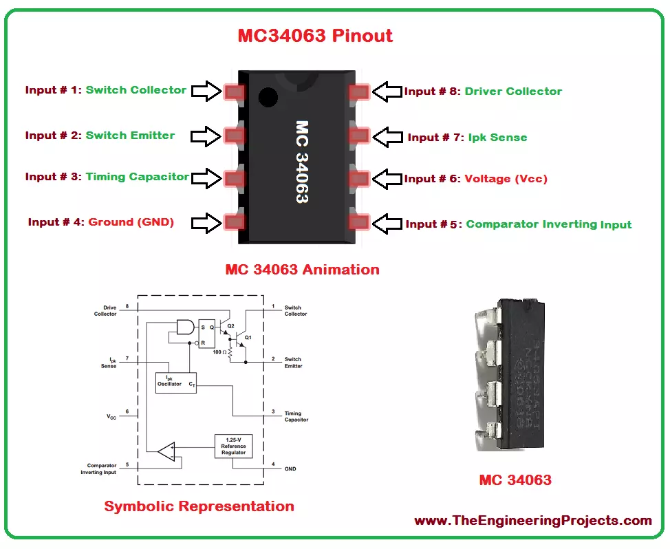
Hello everyone! I hope you all will be absolutely fine and having fun. Today, I am going to share a detailed Introduction to MC34063. It's normally required for the construction of DC to DC converters. MC34063 has a high current output switch, Pulse Width Modulation (PWM) controller with current limiting, compensated reference of internal temperature, a comparator and a driver. For the inverting, boost and buck applications there is no need of a huge complicated external components, instead they can be performed using minimum external components. MC 34063 operates properly in the temperature ranging from 0 to 70 degree celsius. MC34063 ha s wide range of applications in real life e.g. portable equipment, Human Machine Interface (HMI), test and measurement, telecommunications, computing and consumer, cable solutions etc.

Introduction to MC34063

  • MC34063 is basically a monolithic control circuit having all the functions required for the construction of DC to DC converters i.e. buck converter, boost converter or inverters etc.
  • It consists of multiple functions, which are:
    • Comparator.
    • Oscillator.
    • High current output switch.
    • Active Peak Current Limit.
  • MC 34063 requires minimum externals equipment for buck, boost applications.
  • It has a lot applications including, cable solutions, blood gas analyzer, telecommunications etc.
  • The current, voltage and power ratings of MC 34063 are shown in the table given below:
MC34063 Maximum Ratings
No. Parameter Symbol Value Unit
1 Power Supply Voltage Vcc 40 V
2 Comparator Input Voltage Range Vir -0.3 to +40 V
3 Switch Collector Voltage Vc(switch) 40 V
4 Switch Emitter Voltage Ve(switch) 40 V
5 Switch Collector to Emitter Voltage Vce(switch) 40 V
6 Driver Collector Voltage Vc(driver) 40 V
7 Driver Collector Current Ic(driver) 100 mA
8 Switch Current Isw 1.5 A
1. MC34063 Pinout
  • MC34063 is available in DIP, SOIC & SON packages.
  • These packages of MC 34063 has eight (8) pins each.
  • Each of these pins along with its name is shown in the table given below:
MC34063 Pinout
Pin No. Pin Name
1 Switch Collector
2 Switch Emitter
3 Timing Capacitor
4 Ground (GND)
5 Comparator Inverting Input
6 Voltage (Vcc)
7 Ipk
8 Driver Collector
  • I have also labelled these Pins on the IC for better understanding:
2. MC34063 Pins Configuration
  • MC 34063 pins configuration along with the functions associated each of the pin is provided in the table shown below.
  • All the eight pins of MC 30463 with the functions associated with them are shown in table above.
3. MC34063 Proteus Simulation
  • As I have told earlier, MC34063 is used mostly for buck or boost applications.
  • So, I have designed this simple buck converter Proteus Simulation of MC34063, where I have converted voltage from 12V to 5V.
  • Here's the circuit diagram of buck converter shown in below figure:
  • You can see in above figure that input voltage of this buck converter is 12V while the output voltage is 5V.
  • The circuit I have designed in Proteus is kind of a basic circuit of MC34063.
  • By changing the values of resistors and inductor, you can change the output voltage.
  • You can download this Proteus Simulation of buck converter by clicking below button:

[dt_default_button link="https://www.theengineeringprojects.com/ElectronicComponents/Introduction%20to%20MC34063.zip" button_alignment="default" animation="fadeIn" size="medium" default_btn_bg_color="" bg_hover_color="" text_color="" text_hover_color="" icon="fa fa-chevron-circle-right" icon_align="left"]Download Proteus Simulation[/dt_default_button]

4. MC34063 Packages
  • MC 34063 has different packages, a few of which are shown in the table given below.
  • The three packages including PDIP, SOIC and SON along with their dimensions are shown in the above table.
5. MC34063 Features
  • The different features associated with MC 34063 are provided in the table shown below.
  • The description of the features associated with the device MC 34063 are provided in chronological order in the table shown above.
6. MC34063 Schematic Diagram
  • The internal circuitry of the device MC 34063 is shown in the figure given below.
  • From the above figure, you can see that MC 34063 consista of oscillator, 1.25V reference regulator, gate and a combination of transistors etc.
7. MC34063 Applications
There are a lot of applications associated with MC34063, a few of which are given below.
  • Human Machine Interfaces (HMI).
  • Portable devices.
  • Measurement and test.
  • Gas and blood analyzer.
  • Consumer
  • Computing
  • Telecommunications.
  • Cable solutions.
  • These are the few applications associated with MC 34063.
So, that is all from the tutorial Introduction to MC34063. I hope you enjoyed this exciting tutorial. If you are facing any sort of issue regarding anything, you can ask me in comments anytime you want, without even feeling any kind of hesitation. I will try my level best to sortout your problems, if possible. Our entire team is also 24/7 there to entertain you. I will explore further hardware equipment in my upcoming tutorials. So till then, Take Care :)

Introduction to LM386

Hello everyone! I hope you all will be absolutely fine and having fun. Today, I am going to explain you about Introduction to LM386. Its a power amplifier specially designed for low voltage consuming applications. The gain of LM 386 is set around 20 internally. But the gain could be increased due to the insertion of external resistor and capacitor between the pin number 1 and 8. The gain could increase to any value from 20 to 200. The LM-386 inputs are ground referenced. The output are biased to the half of the input voltage levels automatically. When LM 386 operates on 6V, its quiescent power drain is around 24mW. This property of LM-386 makes it ideal for the battery operation. Its major features include battery operation, minimum external parts / equipment, low quiescent current drain, wide supply voltages. LM 386 has avery wide range of applications including intercoms, power converters, TV sound systems, ultrasonic drivers, portable tape player amplifiers, line drivers, AM FM radio amplifier, small servo drivers. Futher detail about LM-386 will be given later in this tutorial. [otw_is sidebar=otw-sidebar-7]

Introduction to LM386

LM386 is a power amplifier used for low voltage application requirement. Its gain is internally set around 20 but due to the external resistor and capacitor gain can vary between 20 to 200. It is assumed to be ideal for the battery operation when operating around 6V. Its has a lot of real life applications e.g. servo drivers, line drivers, TV sound systems, FM radio amplifier etc. LM-386 is show in the figure below.
1. LM386 Pinout
  • LM 386 has eight (8) pins in total having different individual functions.
  • All of the pins along with their symbol are given in the table shown below.
2. LM386 Pins Configuration
  • A properly labeled pin diagram of any device results in better standing of the user.
  • I have made a completely labeled diagram of LM-386 diode along with its animation.
  • The complete pinout diagram along with animation, symbolic representation and the real image of LM 386 is shown in the figure below.
3. LM386 Packages
  • LM 386 has different type of packages LM386N-1, LM386N-3, LM386N-4 and LM386M-1.
  • All of theses packages along with their dimensions and part number are given in the table shown below.
4. LM386 Ratings
  • The current, voltage and power ratings of any device shows its power requirement i.e. how much amount of current and voltage is sufficient for its operation.
  • I have provided LM 386 current, power and voltage ratings in the table shown below.
5. LM386 Schematic
  • The schematic diagram of a device helps us to understand its internal functionality.
  • I have provided the labeled schematic diagram of LM-386 as shown in the figure below.
 
6. LM386 Applications
  • LM386 has a wide range of real life applications, a few of which are given below.
  • AM-FM radio amplifiers.
  • Amplifier with a gain of 20 shown in the figures below.
  • Whereas the amplifier with a gain of 200 shown in the figures below.
  • Line drivers.
  • TV sound systems.
  • Ultrasonic drivers.
  • Power converters.
  • Small servo drivers.
  • Portable tape players.
So, thats all from the tutorial Introduction to LM386. I hope you enjoyed this amazing tutorial. If you have any sort of problem, you can ask me in comments, any time you want, without even feeling a bit of hesitation. I will try me level best to sort out your issues in a better way, if possible. Our team is also 24/7 available to help you out. I will explore further IC's and diodes in my upcoming tutorial and will share them with you as well for sure. So, till then, Take Care :)

Introduction to UA741

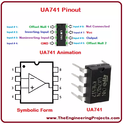
Hello everyone! I hope you all will be fine and having fun. Today, I am going to give you an elaboration on Introduction to UA741. UA 741 is basically a general purpose operational amplifier. This amplifier is considered to be ideal for the voltage follower applications because latch-up operations are no there in its case and it moreover it has High Common Mode Input Voltage Range (HCMIVR). UA-741 is a high performance operational amplifier made up of single silicon chip. UA 741 is stable without using external components, due to the internal frequency compensation and this device is safe from the short  circuiting. In order to cancel the effect of offset voltages we can use a small valued potentiometer/resistor. UA-741 can operate in a temperature ranging from 0 degrees celsius to 70 degrees celsius. This device has several different features including latch-up free operation, large common mode input voltage ranges, short circuit protection, large differential voltage ranges, capability of nulling offset voltages. UA 741 has a lot applications e.g. Digital Versatile Disk (DVD) recorders, audio mixers, DVD players etc.

Introduction to UA741

UA741 is a general purpose amplifier. It is known as an ideal amplifier for voltage follower applications. UA 741 has good stability without even using the external components. This stability is due to the latch-up free operations and high common mode input voltage ranges. It has amazing features like short circuit protection, latch up free operation, no frequency compensation, offset voltage nulling capability, large common mode voltages etc. Its real life applications include audio mixers, DVD recorders, DVD players etc. UA-741 is shown in the figure below.
1. UA741 Pins
  • UA741 has eight (8) pins in total each having different functionality.
  • All of the eight pins along with their names are shown in the table given below.
2. UA741 Pins Description
  • Each of the 8 pins has its own individual feature.
  • The function associated with each pin is given in the table show below.
3. UA741 Pinout
  • Labeled pinout diagram of any equipment provides help in better understanding of the user.
  • A completely labeled diagram of UA 741 along with its animation and schematic is given below.
  • The complete pin diagram along with animation, symbolic representation and the real image of UA-741 is shown in the figure below.
 
4. UA741 Packages
  • UA 741 has 3 type of packages PDIP (8), SO (8), and SOIC (8).
  • The all packages are provided in the table given below below.
5. UA741 Packages Dimensions
  • Each of the three packages has different dimensions.
  • All of the three packages are shown in the table given below.
6. UA741 Ratings
  • The ratings of any equipment like voltage rating, current rating and power rating show the power requirement of that device e.g. how much power, voltage and current is required for its operation.
  • UA 741's current, voltage, power ratings are given in the table shown below.
7. UA741 Schematic
  • Schematic representation of an equipment presents the internal functionality of that equipment.
  • A labeled schematic diagram of UA-741 is given in the figure shown below.
8. UA741 Features
UA741 has several different features as given below.
  • Latch-up free operations.
  • High gain.
  • No frequency compensation required.
  • Large input voltage range.
  • Short circuit protection.
  • Capability of nulling offset voltage.
  • Large differential voltage ranges.
9. UA741 Applications
UA 741 has a lot of real life applications, few of those applications are given below.
  • Functions generator.
  • Integrators.
  • DVD recorders.
  • Summing amplifiers.
  • DVD players.
  • Active filters.
  • Audio mixers.
  • Voltage followers.
This is the detailed discussion about Introduction to UA741. I hope you have enjoyed this exciting tutorial. If you have any of problem, you can ask me in comments any time you want, without feeling any hesitation. I will try my best to solve your issues in some better way, if possible. Our team is also here to help you. I will explore further IC's in my later tutorial and will surely share all of them with you as well. Till then, Take Care :)

Introduction to NE555

Hello everyone! I hope you all will be absolutely fine and having fun. Today, I am going to share my knowledge about Introduction to NE555. NE 555 is a precise timing circuit device. It can produce the precise time delays and oscillations. The time interval can be controlled by external resistor and capacitor when NE-555 operates in mono stable mode.Whereas in adjustable mode two external resistors and one capacitor controls the duty cycle and frequency. NE555 is an Integrated Circuit (IC/Chip) which can be used in different types of timers.  The output circuit is capable of bearing current up to 200mA. NE-555 timer works on voltage ranging from 5V to 15V. The output level have compatibility at 5V supply. NE 555 timer can be used in oscillator applications and pulse generation as well. Further detail about NE-555 will be given later in this tutorial.

Introduction to NE555

NE555 is a timing circuit Integrated Circuit (IC). It produces the accurate oscillations and time delays. It has two modes of operations i.e. mono stable mode and adjustable mode. In mono stable mode time interval is controlled by external resistor and capacitor. Whereas adjustable mode includes the control of duty cycle with two external resistors and a single capacitor. NE 555 timer has several different applications including finger print biometric, RFID reader, Iris biometrics etc. NE 555 timer is shown in the figure below.
1. NE555 Pins
  • NE555 timer has eight (8) pins in total four (4) on the left side of the IC and the remaining four (4) on the right side of the IC.
  • All of the pins are shown in chronological order in the table shown below.
2. NE555 Pinout
  • A properly labeled pin diagram of the device helps user in their better understanding.
  • I have provided a properly labeled diagram of NE 555 along with its animation and schematic.
  • A proper pin diagram along with animation, symbolic representation and the real image of NE-555 is shown in the figure below.
 
3. NE555 Packages
  • NE 555 has four (4) different types of packages TSSOP, SOIC (16), PDIP (16) and SOP (16).
  • All of the four packages are given in the table shown below.
4. NE555 Package Dimensions
  • Each of the package has different individual dimensions.
  • The dimensions of all of the MAX 232 packages are shown in the table given below.
5. NE555 Functional Diagram
  • The functional diagram of any device presents the complete working of that device.
  • Functional diagram of NE 555 is shown in the figure below.
6. NE555 Features
The features associated with NE 555 timer are given below.
  • Timing from micro seconds to hours.
  • Adjustable or mono stable operation.
  • Adjustable duty cycle.
  • TTL compatible output up to 200mA.
  • Lead (Pb) free/
  • RoHS compliant.
  • Green molding compund.
7. NE555 Ratings
  • Current, power and voltage ratings of a device presents the power requirement of that device i.e. how much voltage, power and current is necessary for its operation.
  • I have provided NE555 current, voltage, power ratings in the table shown below.
8. NE555 Applications
NE 555 timer has several different real life applications, some of them are given below.
  • RFID reader.
  • Finger print biometrics.
  • Iris biometrics.
So, that was all the necessary detail about Introduction to NE555. I hope you enjoyed my tutorial. If you have any sort of problems, you can ask me in comments, any time you want so, without even feeling any type of hesitation. I will try my best to sort out your issues in a better way, if possible. Our team is also available to entertain you. I will explore further IC's in my upcoming tutorials and will share all of them with you as well. So, till then, Take Care :)
Syed Zain Nasir

I am Syed Zain Nasir, the founder of <a href=https://www.TheEngineeringProjects.com/>The Engineering Projects</a> (TEP). I am a programmer since 2009 before that I just search things, make small projects and now I am sharing my knowledge through this platform.I also work as a freelancer and did many projects related to programming and electrical circuitry. <a href=https://plus.google.com/+SyedZainNasir/>My Google Profile+</a>

Share
Published by
Syed Zain Nasir