Hey guys! I hope you are doing good and having fun. Today, I am going to unlock the details on the Introduction to Resistors. Resistor is a two terminal component that is used to restrict the flow of current. Resistors are widely used in electrical circuits. They come in different forms ranging from variable resistors to fixed resistors. Depending on the feature of resistors, both are used in many applications. I am going to cover all aspects relating to resistors. Let's get started.
Introduction to Resistors
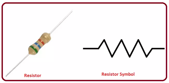
A resistor is a two-terminal device that is used to resist the flow of current. It is one of the most commonly used components in electrical circuits.
Resistance of any resister is described in ohms. Ohm is denoted by the Greek letter om ...
Hey Fellas! Hope you are doing great. Today I am going to give you the details on Introduction to 2n5320. It is basically a Bipolar NPN (Negative Positive Negative) Transistor (BJT), which contains two layers of N-doped semiconductor and one layer of P-doped semiconductor. P, layer lies between two N layers. Here P represents the Base of the transistor and two N layers show emitter and collector respectively.
This NPN transistor has a wide range of applications. It is mainly used for power amplification and switching purpose.You should also have a look at Introduction to BC547 which is also an NPN transistor. So, let's get started with Introduction to 2n5320:
Introduction to 2n5320
2n5320 is a bipolar Switching Silicon transistor, which is mo ...
Hello friends, I hope you all are doing great and having fun in your lives. In today's tutorial, we are gonna design a Heart Beat Monitor using Arduino in Proteus ISIS. You should download this Heart Beat Sensor Library V2.0 for Proteus because we are gonna use that to detect heart beat in Proteus.
I have also used a 20x4 LCD which will display our heart rate value. You should download this New LCD Library for Proteus. I have counted the heart beat for ten seconds and then I have multiplied it with 6 to get the heartbeat per minute which is abbreviated as bpm (beats per minute). So, let's get started with Heart Beat Monitor using Arduino in Proteus ISIS.
Heart Beat Monitor using Arduino in Proteus
First of all, click the below button to downloa ...
Hello friends, I hope you all are doing great. In today's tutorials, I am gonna share a new C945 Library for Proteus. If you have searched for this transistor in Proteus, then you must have known that it's not available in Proteus. We have designed this transistor in Proteus and here's its library.
If you don't know much about this transistor then you should have a look at Introduction to C945, in which I have explained in detail the basics of this transistor. Today, first of all, I will show you How to install this library and after that we will design a simple Proteus Simulation in which we will see How to simulate C945 in Proteus. You should also check this amazing list of New Proteus Libraries for Engineering Students. So, let's get started wi ...
Hello friends, I hope you all are doing great. In today's tutorial, we are gonna design a project named DC Motor Control using XBee & Arduino in Proteus ISIS. I have shared the complete code and have also explained it in detail. You can also download the complete working Proteus Simulation given at the end of this tutorial. In this project, I have designed two Proteus Simulations.
The first Simulation is of Remote control in which I have used a keypad. The second simulation contains our two DC Motors and I am controlling the direction of those DC Motors with my Remote Control. XBee Module is used for sending wireless data. The code will also work on hardware as I have tested it myself. So, let's get started with DC Motor Control using XBee &am ...
Hello everyone, I hope you all are doing great. In today's post, I am going to share a Final Year Project in detail, named as Real Time Security Control System using XBee and GSM. I will give you all the details so that you can easily design it on your own. I've given the Proteus Simulation to download below. In that zip file, you will get both the Arduino codes and Proteus Simulations.
I have divided this whole project design into four parts. If you got into any trouble in your project, then ask in comments and I will try my best to resolve them. So, today we are gonna have a look at the basics of this Security project. There are a lot of systems introduced in the market these days that are used to transfer sensor data from one node to another ei ...
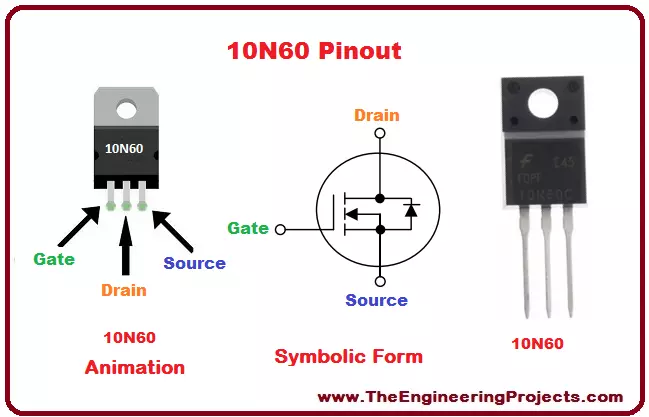
Hello everyone! I hope you all will be absolutely fine and having fun. Today, I am going to provide you a detailed discussion on Introduction to 10N60. Before going into the details of this article you should also have a look at Introduction to 4N60, 78M05, 2N3772, 2SC3320, 20N60. It is basically a high voltage Metal Oxide Semiconductor Field Effect Transistor (MOSFET). It is a power MOSFET and is able to control the certain level of the power. 10-N-60 is also a high current power MOSFET. This device has three terminals and is made up of silicon. It has around 10 ampere of current conduction capability i.e. this device is able to conduct 10A of current through it. 10-N-60 has a lot of amazing features.
It features include low on-state resistance ...
Buy This Project
Hello everyone, I hope you all are doing great. Today, I am going to share a new Project which is Smart Blind Stick using Arduino in Proteus ISIS. I have designed its complete Simulation which I am gonna share today. We have designed this Proteus simulation off Smart Blind Stick after quite a lot of effort that's why its not free. We have placed a small amount on it and you can buy it from our shop via PayPal. You need to click on above button in order to buy this project's code and Simulation. If you have any problem in understanding this project, then you can ask in comments and I will try my best to resolve your issues.
Smart Blind Stick project is designed quite a lot in engineering universities. That's why, I thought of sha ...
Hello everyone! I hope you will absolutely fine and having fun. Today, I am going to give you a detailed discussion on the topic Introduction to 4N60. I have shared characteristics of the different IC's in my previous tutorials in Introduction to 75N75, SG3524, 2N3772, L298, L293D, 2SC3320 and 20N60. You must need to go through all these tutorials for the better understanding of today's article. 4N-60 is a high voltage Metal Oxide Semiconductor Field Effect Transistor (MOSFET). It is a three pin device including drain (D), gate (G) and source (S).
4N60 is basically a power MOSFET and is able to handle the certain levels of power. It is specially designed to achieve the different characteristics e.g. high speed switching time, low charge on gate ...
Hello everyone, I hope you all are doing great. Today, I am going to share a new L298 Motor Driver Library for Proteus. It has never been designed before and we are proudly presenting it for the first time. I hope you guys are gonna like it. You should also have a look at DC Motor Speed Control using L298 in which I have used the same module in hardware design. But today we are gonna see it in action in Proteus Simulation and its quite exciting for me as well. :)
If you don't know much about L298 then you should also have a look at Introduction to L298, in which I have discussed the basics of L298 module, it will be quite informative for you. If you got into any trouble regarding this L298 Motor Driver Library for Proteus, then you can ask in comm ...