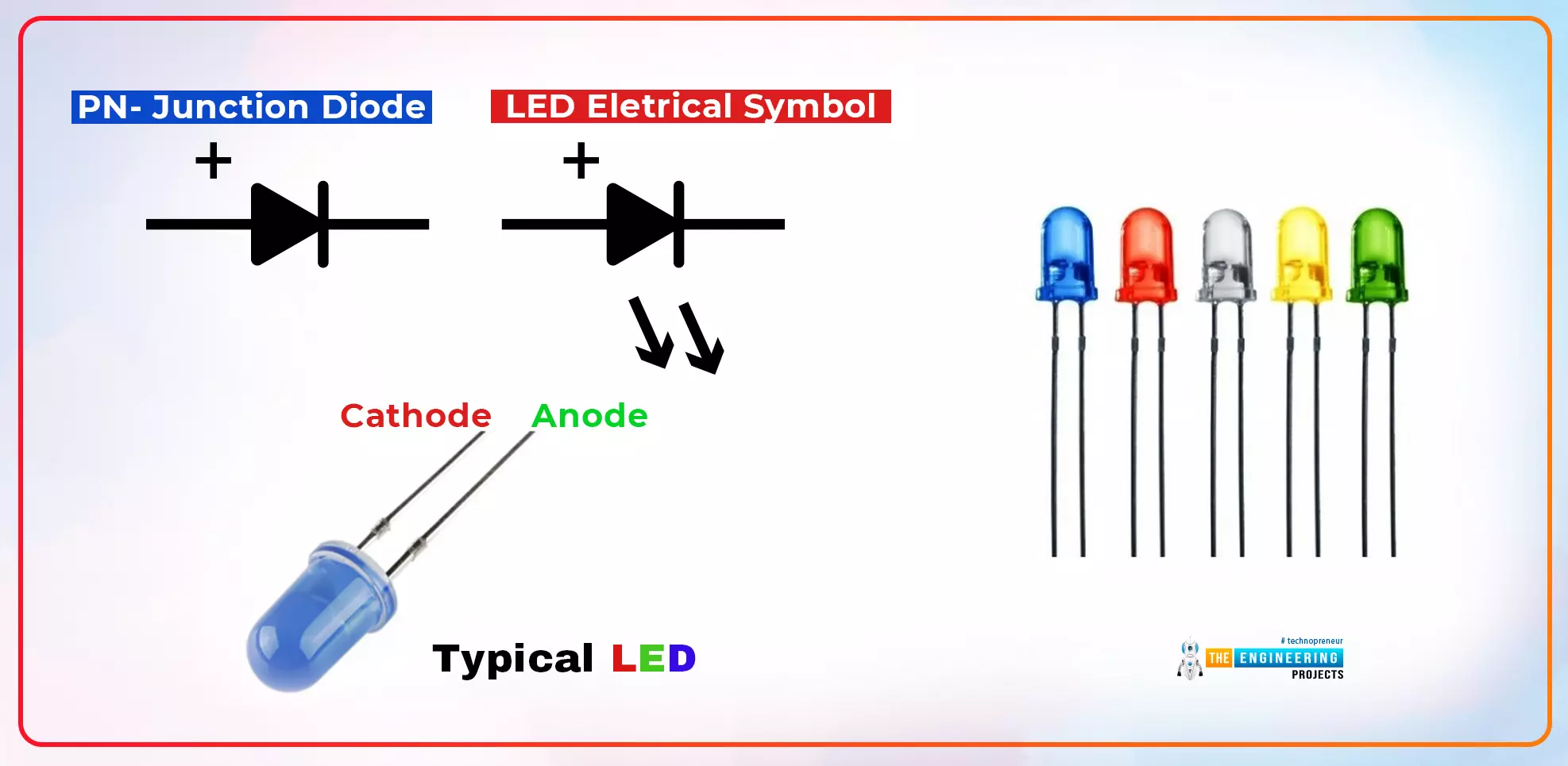
Introduction to Arduino IDE

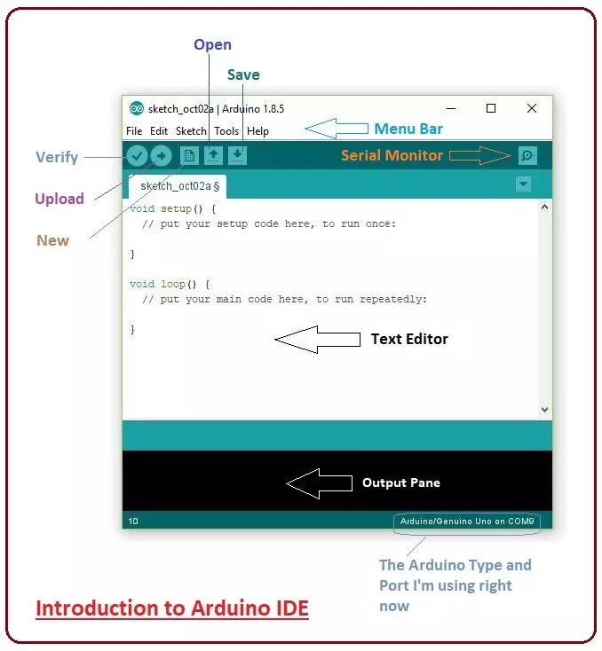
Hey Guys! Hope you are doing well. Today, I'll discuss the detailed Introduction to Arduino IDE, where IDE stands for Integrated Development Environment - An official software introduced by Arduino.cc, that is mainly used for writing, compiling and uploading the code in almost all Arduino modules/boards. Arduino IDE is open-source software and is easily available to download & install from Arduino's Official Site.

In this post, I'll take you through the brief Introduction of the Software, how you can install it, and make it ready for your required Arduino module. Let's dive in and get down to the nitty-gritty of this Software.

Where To Buy?
No.ComponentsDistributorLink To Buy
1Arduino UnoAmazonBuy Now

Introduction to Arduino IDE

  • Arduino IDE is an open-source software, designed by Arduino.cc and mainly used for writing, compiling & uploading code to almost all Arduino Modules.
  • It is an official Arduino software, making code compilation too easy that even a common person with no prior technical knowledge can get their feet wet with the learning process.
  • It is available for all operating systems i.e. MAC, Windows, Linux and runs on the Java Platform that comes with inbuilt functions and commands that play a vital role in debugging, editing and compiling the code.
  • A range of Arduino modules available including Arduino Uno, Arduino Mega, Arduino Leonardo, Arduino Micro and many more.
  • Each of them contains a microcontroller on the board that is actually programmed and accepts the information in the form of code.
  • The main code, also known as a sketch, created on the IDE platform will ultimately generate a Hex File which is then transferred and uploaded in the controller on the board.
  • The IDE environment mainly contains two basic parts: Editor and Compiler where former is used for writing the required code and later is used for compiling and uploading the code into the given Arduino Module.
  • This environment supports both C and C++ languages.

How to Download Arduino IDE

You can download the Software from Arduino main website. As I said earlier, the software is available for common operating systems like Linux, Windows, and MAX, so make sure you are downloading the correct software version that is easily compatible with your operating system.

  • If you aim to download the Windows app version, make sure you have Windows 8.1 or Windows 10, as the app version is not compatible with Windows 7 or older version of this operating system.
  • You can download the latest version of Arduino IDE for Windows (Non-Admin standalone version), by clicking below button:
Download Arduino IDE

The IDE environment is mainly distributed into three sections

  1. Menu Bar
  2. Text Editor
  3. Output Pane

As you download and open the IDE software, it will appear like an image below:

The bar appearing on the top is called Menu Bar that comes with five different options as follow

  • File - You can open a new window for writing the code or open an existing one. The following table shows the number of further subdivisions the file option is categorized into.
  • As you go to the preference section and check the compilation section, the Output Pane will show the code compilation as you click the upload button.
  • And at the end of the compilation, it will show you the hex file it has generated for the recent sketch that will send to the Arduino Board for the specific task you aim to achieve.
  • Edit - Used for copying and pasting the code with further modification for font
  • Sketch - For compiling and programming
  • Tools - Mainly used for testing projects. The Programmer section in this panel is used for burning a bootloader to the new microcontroller.
  • Help - In case you are feeling skeptical about software, complete help is available from getting started to troubleshooting.

The Six Buttons appearing under the Menu tab are connected with the running program as follows.

  • The checkmark appearing in the circular button is used to verify the code. Click this once you have written your code.
  • The arrow key will upload and transfer the required code to the Arduino board.
  • The dotted paper is used for creating a new file.
  • The upward arrow is reserved for opening an existing Arduino project.
  • The downward arrow is used to save the current running code.
  • The button appearing on the top right corner is a Serial Monitor - A separate pop-up window that acts as an independent terminal and plays a vital role in sending and receiving the Serial Data. You can also go to the Tools panel and select Serial Monitor, or pressing Ctrl+Shift+M all at once will open it instantly. The Serial Monitor will actually help to debug the written Sketches where you can get a hold of how your program is operating. Your Arduino Module should be connected to your computer by USB cable in order to activate the Serial Monitor.
  • You need to select the baud rate of the Arduino Board you are using right now. For my Arduino Uno Baud Rate is 9600, as you write the following code and click the Serial Monitor, the output will show as the image below.
  • The main screen below the Menu bard is known as a simple text editor used for writing the required code.
  • The bottom of the main screen is described as an Output Pane that mainly highlights the compilation status of the running code: the memory used by the code, and errors that occurred in the program. You need to fix those errors before you intend to upload the hex file into your Arduino Module.
  • More or less, Arduino C language works similar to the regular C language used for any embedded system microcontroller, however, there are some dedicated libraries used for calling and executing specific functions on the board.

Arduino Libraries

  • Libraries are very useful for adding extra functionality into the Arduino Module.
  • There is a list of libraries you can check by clicking the Sketch button in the menu bar and going to Include Library.
  • As you click the Include Library and Add the respective library it will be on the top of the sketch with a #include sign. Suppose, I Include the EEPROM library, it will appear on the text editor as

#include <EEPROM.h>

  • Most of the libraries are preinstalled and come with the Arduino software. However, you can also download them from external sources.

Making Pins Input or Output

The digitalRead and digitalWrite commands are used for addressing and making the Arduino pins as an input and output respectively.

These commands are text sensitive i.e. you need to write them down the exact way they are given like digitalWrite starting with small "d" and write with capital "W". Writing it down with Digitalwrite or digitalwrite won't be calling or addressing any function.

How to Select the Board

  • In order to upload the sketch, you need to select the relevant board you are using and the ports for that operating system.
  • As you click the Tools on the menu, it will open like the figure below:
  • Just go to the "Board" section and select the board you aim to work on. Similarly, COM1, COM2, COM4, COM5, COM7 or higher are reserved for the serial and USB board. You can look for the USB serial device in the ports section of the Windows Device Manager.
  • The following figure shows the COM4 that I have used for my project, indicating the Arduino Uno with the COM4 port at the right bottom corner of the screen.
  • After correct selection of both Board and Serial Port, click the verify and then upload button appearing in the upper left corner of the six-button section or you can go to the Sketch section and press verify/compile and then upload.
  • The sketch is written in the text editor and is then saved with the file extension .ino.

It is important to note that the recent Arduino Modules will reset automatically as you compile and press the upload button the IDE software, however, the older versions may require the physical reset on the board.

  • Once you upload the code, TX and RX LEDs will blink on the board, indicating the desired program is running successfully.
Note: The port selection criteria mentioned above are dedicated to Windows operating system only, you can check this Guide if you are using MAC or Linux.
  • The amazing thing about this software is that no prior arrangement or bulk of the mess is required to install this software, you will be writing your first program within 2 minutes after the installation of the IDE environment.

Arduino Bootloader

  • As you go to the Tools section, you will find a bootloader at the end.
  • It is very helpful to burn the code directly into the controller, setting you free from buying the external burner to burn the required code.

When you buy the new Arduino Module, the bootloader is already installed inside the controller. However, if you intend to buy a controller and put it in the Arduino module, you need to burn the bootloader again inside the controller by going to the Tools section and selecting the burn bootloader.

That's all for today. I hope I have given you everything you needed to know about Arduino IDE. If you are unsure or have any questions, you can ask me in the comment section below. I'd love to help you the best way I can. You are most welcome to keep us updated with your valuable feedback and suggestions, they help us provide you quality work so you keep coming back for what we have to offer. Thanks for reading the article.

Introduction to Arduino Micro

Hey Guys! Hope you are getting along with life pretty well. Welcome you onboard. Today, I'll unlock the details on the Introduction to Arduino Micro. It is a Micro board, based on the ATmega32U4 microcontroller and comes with built-in USB, making it easily compatible with the computer. Arduino Micro, as the name suggests, is the smallest board in the Arduino Community. It is comparable to its counterparts like Arduino Nano and Arduino Promini. In this tutorial, I'll discuss each and everything related to Micro board including its main features, pinout, pin description, the software used and applications. Let's dive in and explore everything you need to know about this tiny board.

Introduction to Arduino Micro

  • Arduino Micro is the smallest board in the Arduino Community and is mainly based on the ATmega32U4 microcontroller.
  • It contains a built-in USB on the tiny easy to integrate interface, that helps in laying out a prompt connection with the computer.
  • Don't get into the illusion of performing complex functions that require more memory space, as this little toy comes with flash memory around 32 KB while EEPROM and SRAM are 2.5 KB and 1 KB respectively, still enough to wet your technical appetite.
  • The maximum length and width of the Micro PCB are 4.8cm and 1.77cm respectively, however, with the attached USB port the dimensions will slightly be larger than the given parameters, exceeding from the edge of the PCB layout.
  • Breadboard compatibility makes this device easy to use for getting a hands-on experience before incorporating it in the relevant project with all prerequisites.
  • You can download Arduino Micro Datasheet by clicking below button:
Download Arduino Micro Datasheet
  • The ATmega32U4 microcontroller available on the board features UART communication with TX and RX pins.
  • The Micro board incorporates resettable poly-fuse that that is mainly used for securing computer's USB ports from shorts and overcurrent by providing an extra layer of protection.
  • If the current escalates from the required value to the USB port, the fuse will jump in and work as an emergency switch, breaking the connection between the board and computer. It is advised to keep the provided current to the USB port under 500mA.

1. Arduino Micro Features

If you are aiming to pick this Arduino module for your relevant project, it is advised to get a hold of its features in order to avoid any hassle in future. The following figure shows the main features of Arduino Micro.
Microcontroller ATmega32U4
CPU 8-Bit
Digital I/O Pins 24
PWM Output 7
Analog Input 12
Flash Memory (Program Memory) 32 KB
SRAM 2.5 KB
EEPROM 1 KB
Input Voltage 7-12 V
Operating Voltage 5 V
Oscillator up to 16 MHz
Software Used Arduino Software (IDE)
Reset Button Yes
ICSP Header Yes
USB Port 1
UART (Serial Communication) Yes
  • Serial communication along with SPI and I2C communications are available on the board. The physical reset button is added that helps to stop the running function and puts the controller in the initial condition from where it takes and implements the stored information from scratch.

2. Arduino Micro Pinout

Following figure shows the Arduino Micro Pinout diagram.
  • You may have heard, at times, tiny things work wonders. Same is true with this module. It is nothing but a technical peripheral device with a number of features laid out and housed in one package.
  • Still, as I have mentioned earlier, it operates perfectly if you plan to design the simple project that requires less memory space. Arduino Due and Arduino Leonardo are preferred to meet your technical needs if your project requirements are complex and require more memory space in order to design and drive automation in the relevant project.
  • The built-in USB communication on the board removes the need for a secondary processor and helps it to appear to a connected computer as a keyboard and mouse, in addition to a virtual (CDC) serial / COM port.

3. Arduino Micro Pin Description

Until now, you have got a brief overview of this device and how this module can be a good fit for your project. In this section, I'll discuss the pin description with images, you can easily grab the idea what are the major functions associated with each pin. Let's get to the point.
Analog Input
There are 12 analog inputs on the board. You can see them in the figure below.
Communication Protocols
Communication protocols like serial, SPI and I2C are incorporated on the board. You can see them highlighted on the figure below.
PWM Output
Seven pins are used for PWM output purpose. It is a process for getting analog results with digital means. You can see PWM in the figure below.
Power Source
The 5V is a voltage at which board operates while 3.3V is the operating voltage of each pin. The Vin is the input voltage that ranges between +7 to +12 V and is a  voltage from the external power source, not from a USB port. There are two ground pins on the board. The AREF predicts the Analogue reference voltage that helps to inject the Arduino a reference voltage from an external power supply. You can see the power source in the figure below.
External Interrupt
PCINT are the external interrupts generated on any digital I/O pin. The following figure shows the pins on which external interpret can be generated.
ICSP Header Pins
ICPS head is added on the board and it stands for In-Circuit Serial Programming - A feature used for programming Arduino with another Arduino. And if USB port is not available, it comes out handy for connecting the board with a computer for uploading a sketch.

4. Programming

  • Arduino Software, called IDE, is mainly used for programming the Arduino module and it works perfectly with common operating systems like Windows, Linux or MAC. You can download it from the Arduino site and it is compatible with all versions in the Arduino family.
  • You are ready to use the software as you install it. Some simple LED programs are already available on the software so you can easily start working on the board and compile the default program with the intention you are getting the results on the fly.
  • Built-in bootloader that comes with the board lets you off the hook from wresting your mind for compiling and burning the code using the external burner.
  • Micro board features a serial peripheral interface (SPI) that is mainly used in the communication between the microcontroller and other peripheral devices such as shift registers and sensors. Two pins are used for SPI communication i.e. MOSI (Master Output Slave Input) and MISO (Master Input Slave Output) - they are used for sending and receiving the data by the microcontroller.
  • The Serial Monitor is added in Arduino Software, that plays a vital role in transmitting textual data to or from the board.
  • The TX and RX pins are used for serial communication where TX pin transmits the serial data while RX receives the serial data.
  • The board is capable to perform I2C communication using two pins called SDA and SCL.

5. Difference between Arduino ProMini and Arduino Micro

  • There is a little difference between Arduino ProMini and Micro board, however, peripherals on these boards are same.  The built-in USB in the Micro board proves to be a candid difference between two modules while Promini requires FTDI cable in order to generate USB power and communication to the board.
  • The USB on Micro board can act as a number of ways: Keyboard or mouse, USB hard drive, USB to serial Converter and MIDI controller.
  • The Arduino Pro Mini incorporates ATmega328 microcontroller while Arduino Micro comes with ATmega32U4. Flash memory is the same on both modules however, SRAM differs slightly with 2KB on the ProMini and 2.5 KB on the Micro board.
  • Last not least, the Arduino Pro Mini features 2 hardware interrupts while the Micro board comes with 5 hardware interrupts.

6. Arduino Micro Projects and Applications

Arduino micro comes with a wide range of applications with the ability to groove in hard to reach places. It offers a high number of connections with a minimum interface. The outstanding ability of this board to disguise keyboard or mouse while connected with a computer makes it an ideal choice for many computer applications. You can use this board for the development of the following projects.
  • USB Joystick
  • Electric Bike
  • Windows PC lock/unlock application
  • Creating wireless keyboard
  • Automatic Pill Dispenser
  • USB Trackpad
  • Water Level Meter
There is a list of projects you can create but I have mentioned a few of them to give you an idea what this tiny thing can help in designing a product ranging from embedded, automation to computer applications. That's all for today. I hope I have given you everything you needed to know about Arduino Micro. However, if you are unsure and consider something is left unsaid, making it difficult for you to grab the basic idea, you can approach me in the comment section below. I'd love to help you the best way I can. Keep your feedback and suggestions coming and help us create a quality content as per your needs and requirements. Thanks for reading the article.

Introduction to Arduino LilyPad

Hi Friends! Hope you are doing well. Today, I'll give you a detailed Introduction to Arduino LilyPad. It is an Arduino Microcontroller Board, based on ATmega168/ATmega328 and is introduced by Leah Buechley and SparkFun Electronics.

This board is mainly developed for e-textiles and wearables projects. As per the designed purpose, it can be attached to fabric, sensors, power supplies, and actuators. You may need a conductive thread for joining this board with the required object.

In this post, I'll try to cover each and everything related to Arduino LilyPad, what is this about and how it is used for the development of desired projects. Let's jump right in and get down to the nitty-gritty of this board.

Where To Buy?
No.ComponentsDistributorLink To Buy
1Arduino LilypadAmazonBuy Now

Introduction to Arduino LilyPad

  • Arduino LilyPad is an Arduino Main Board that is mainly designed for e-textiles and wearables projects and is based on the Atmega168/Atmega328 microcontroller.
  • LilyPad is nothing but an Arduino-programmed microcontroller and works similar to other Arduino boards available.
  • It comes in a round shape unlike other Arduino boards so that it could fit easily in wearables.
  • However, the ability of this board to be sewn down with the fabric or sensor through conductive thread puts it ahead and stands out of the boards available in the Arduino community.
  • There are 22 wide open pin-holes, appear around the edge of the whole rounded shape that is mainly used for the connection with the fabric and sensor through a conductive thread.
  • Out of these 22 pinholes, one is reserved for +5V, and one for ground.
  • The LilyPad Arduino incorporates 6 analog inputs that can also be used as digital I/O. They are marked as A0 through A5 on the board, providing 10 bits of resolution. It is important to note that, the analog inputs measure from ground to 5 volts, however, the upper end of their range can be modified using the analogReference() function.
  • The board contains 14 digital pins that can be employed as an input or output, using pinMode(), digitalWrite(), and digitalRead() functions.
  • Like other boards in the Arduino, this Pad is programmed by Arduino IDE - an official software mainly used for programming the Arduino Boards, that is developed by Arduino.cc
  • The board comes with a wide voltage range and operates anywhere between 2.7 V to 5.5 V. The pins on the board come with the ability to control and handle the input or output of the attached device.
  • There are two ways to keep your Pad null and void: increase the operating voltage above 5.5 V or plug the power in reverse order.
  • As I mentioned earlier bootloader is used for storing the code and burning it on the board, however, you can also bypass the bootloader and program the ATmega328 using ICSP (In-Circuit Serial Programming) header.

Arduino LilyPad Features

Following are the main features of the Arduino LilyPad.
Microcontroller ATmega168 or ATmega328V
Digital I/O Pins 14
Analog Input Channels 6
PWM Channels 6
Crystal Oscillator 8 MHz
Flash Memory 16 KB (of which 2 KB used by bootloader)
Bootloader Memory Out of 16KB in the Flash Memory, 2KB is reserved for Bootloader
SRAM1 KB 1 KB
EEPROM 512 bytes
Operating Voltage 2 to 5 V
DC Current per I/O Pin 40 mA
Internal pull-up resistor 20 kO

Arduino LilyPad Pinout

  • Arduino Lilypad Pinout is shown in the below figure:
  • There is a candid difference between external interrupt pins and PCINT pins. Former is the dedicated hardware pin used for generating the interrupt while later is the interrupt that can be created on any digital I/O pin.
  • There are 6 PWM tabs on the board, shown by the dashed lines on the pinout image above. These PWM pins can also be used as digital I/O pins.

How to program Arduino LilyPad?

You can layout the LilyPad connection by following the given steps.
  • Be careful while connecting the power and ground pins of the board. The +5V power must be connected to the positive tab on the board and the ground tab of the board should be connected to the ground of the power source. The reverse connection can cause severe damage to the board and in a worst-case scenario, your board may stop working all at once.
  • There are two ways to generate a regulated +5V power source: Using a +5V pin of the Mini USB Adapter or employing another 2.7-5.5V power source using a Lithium rechargeable battery.
The following figure shows the LilyPad connection with Mini USB Adapter:
  • You can see the two circular tabs on the board marked as TX and RX that are mainly used in two ways: For uploading new sketches to the board and establishing a serial communication with other devices.
  • Apart from using your own power supply, you can also use Mini USB Adapter or Arduino NG board for connecting the Pad with the computer.

The following figure shows the connection of the Arduino UNO with LilyPad:

Note: Don't forget to remove the ATmega8 or ATmega168 from the NG before connecting it with the LilyPad. You can use alligator clips and jumper wires for connecting the +, -, TX and RX tabs on the LilyPad with the corresponding pins on the NG board.

Applications

  • LilyPad is really very handy for e-textile and wearable products, because of its small size.
  • Arduino Lilypad is used in IoT products and embedded projects as well.
  • The circular tabs covering the whole Pad at the edge are mainly used for the connection between Pad and wearable products.

That's all for today. I hope this read has succeeded in grappling your attention and resonated with your field of interest. If you are feeling dubious in any area of the information related to the Pad that I have left unfolded, you can approach me in the comment section below. I'd love to help you according to the best of my expertise. Keep visiting us for valuable information related to engineering and technology. Thanks for reading the article.

How to use digitalWrite Arduino Command

Hey Friends! Hope you are doing well. Today, I'll discuss the details on How to use digitalWrite Arduino Command. The digitalWrite command in Arduino is used for writing the status of the digital Pin. The Pin assigned to this command must be an OUTPUT pin so that it can transfer data to other components like LEDs, motors, and actuators and use them as per your needs and requirements. Arduino boards have always been a great choice for both experts and newbies, as they come with built-in peripheral functions, and no need of external components is required to drive automation and develop some basic functions on the relevant project. Basic Arduino Software is used as a compiler and no separate burner is required to burn the required code into the board. You can simply plug the board with the computer through a USB cable and burn and compile the program by a single click on the software.

How to use digitalWrite Arduino Command

  • digitalWrite Arduino Command is used to write the status of digital Pins, and can make them either HIGH or LOW. The Pin needs to be an OUTPUT Pin.
  • We are working on Arduino UNO, that comes with 14 digital I/O pins and 6 analog pins. You can set these pins as an input or output using pinMode based on your technical requirements.
  • These pins are labeled as 0 to 13 on the board including two serial pins called Tx and Rx appearing at the start and marked as 1 and 0 pins respectively.
  • We set Pins as an INPUT when we want to read or receive data from some component like sensors. And making pins as an OUTPUT will require a digitalWrite function to write or send data to the required device like LEDs, motors etc.
  • When any pin is set an as OUTPUT using the pinMode Arduino Command, it will appear as HIGH or LOW depending on the voltage applying on the pin. For voltage above 3.3V it will appear as HIGH and for GND (ground) it will appear as LOW on the software.
  • Before connecting an LED to pin, make sure to set pinMode as OUTPUT when you call the digitalWrite function, otherwise LED won't be flashing with clear bright light.
Syntax for digitalWrite Arduino
  • Here’s the syntax used for digitalWrite Arduino command:

digitalWrite(pin, value);

where:
  • The "pin" defines the Arduino pin number used. It has to be an OUTPUT Pin.
  • And "value" defines if the pin will be HIGH or LOW.
  • For example:

digitalWrite(8, HIGH);

Note: 
  • It is worth mentioning here that digitalWrite command doesn’t store or return any value unlike most of the commands used in Arduino that help in storing some value.
Difference between analogWrite and digitalWrite
Both terms analogWrite and digitalWrite are used for same purpose i.e. sending data from Arduino, but:
  • The former is used to send data in analog form i.e. 0V - 5V.
  • The later only defines the HIGH and LOW value of the desired pin where HIGH is an indication, pin is getting 5V and LOW is an indication pin is set to ground or zero voltage.
That's all for today. I hope you have found this article informative. If you are unsure or have any question, you can ask me in the comment section below. I'd love to help you according to the best of my expertise. You are most welcome to keep us updated with your valuable feedback and suggestion - they help us provide you quality work so you keep coming back every now and then. Thanks for reading the article.

How to use pinMode Arduino Command

Hi Friends! Hope you are doing well. In this post, I'll uncover the details on How to use pinMode Arduino Command. The pinMode defines the Arduino Pins, if they are used as an input or output. The INPUT_PULLUP is another option achieved by pinMode, that is mainly used to place a virtual pull-up resistor to the input pins. We have started Arduino Tutorials for Beginners quite a while now for the newbies, who are really interested to get a hands-on experience with Arduino. Generally, Arduino is known as a Microcontroller, but it is a step ahead of it. The PIC microcontrollers require some basic circuit to start with but Arduino brings revolution in the automation industry by removing the need of developing any basic circuit. Although Atmega328 is the Microcontroller used in Arduino UNO. Also, the burner is required to burn the program in PIC Microcontrollers, while there is no need to connect separate burner with the Arduino - simply plug it with the computer through a USB cable and start playing with it. In this tutorial, we will thoroughly discuss what is pinMode and how to use it in the Arduino module. Let's jump right in and explore what is this about and everything you need to know.

How to use pinMode in Arduino

  • The Arduino Board comes with GPIO (general purpose input output) pins that can be used in two ways i.e. input, output.
  • pinMode Arduino Command is used to define the operation of these Input/output pins, there are three types of modes that can be assigned using this command and are named as:
    • OUTPUT.
    • INPUT.
    • INPUT_PULLUP.
  • There are 14 digital and 6 analog pins in the module that mainly depend on the pinMode for setting up their mode of operation as an input or output.
  • In this post we mainly discuss the Arduino UNO, that is based on ATmega328 microcontroller, however, you can use other modules like Pro Mini, Mega or Leonardo as per your needs and requirements. The pinMode works same in the module no matter what type of Arduino version you are using.
Syntax for pinMode Arduino
Here's the syntax for our pinMode Arduino command:

pinMode(pin#, mode);

where:
  • Pin defines the Arduino pin number used.
  • There are three types of modes that can be assigned to pins of Arduino, which are:
    • OUTPUT
    • INPUT
    • INPUT_PULLUP
Let's use Pin # 8 of Arduino and assign all possible modes to it:

pinMode(8, OUTPUT);

pinMode(8, INPUT);

pinMode(8, INPUT_PULLUP);

Note: 
  • It is important to note that, unlike most of the functions used in the C code for Arduino module, this pinMode doesn't store or return any value.
  • You have to use any one of these three modes at a time.
Modes of pinMode Arduino
  • In the previous section, we have discussed the basic syntax of pinMode, and I hope you have pretty much got the basic idea behind it.
  • The only thing worth mentioning here is the difference between INPUT and INPUT_PULLUP.
  • So, here's a simple code where I have made Pin # 8 as an INPUT and read its status on Serial Monitor.
int Pin = 8;

int Status = 0;

void setup()
{
  Serial.begin(9600);
  pinMode(Pin, INPUT);          
}

void loop()
{
  Status = digitalRead(Pin);       
  
  if(Status == HIGH)
  {
    Serial.println("HIGH");
  }

  if(Status == LOW)
  {
    Serial.println("LOW");
  }
 
}
  • Let's have a look at the Serial Monitor:
  • While taking the above image, Pin # 8 was in open state and we are getting just random values.
  • We are getting these random values i.e. HIGH, LOW because our Pin#8 is neither connected to +5V nor GND.
  • Arduino seems confused here, and we can remove this confusion by simply changing INPUT to INPUT_PULLUP.
  • As we run the Serial Monitor, we will get something shown below:
  • You can see how we are getting HIGH value only, while the pin is still in open state.
  • We can conclude, when we have nothing on our INPUT pin then INPUT_PULLUP will make the pin HIGH.
Difference between Read and Write
There are two ways to send or receive data. You can either define the pin as an input that helps in reading the data from an external device like sensors. Or you can define pin as an output that helps in writing and sending a command to LEDs, motors or actuators for executing the desired functions. That's all for today. I hope you have found this post informative as per your needs and requirements and can easily use this pinMode Arduino Command. If you are feeling skeptical or have any question, you can ask me in the comment section below. I'll try and help you according to the best of my expertise. Thanks for reading the article.

Introduction to CR2032

Hey Guys! Hope you are doing well. Welcome you onboard. Today, I'll discuss the details on the Introduction to CR2032 Battery. It is known as a coin cell or button cell that comes in cylindrical form and is mainly used in pocket calculators, wrist watches, artificial cardiac pacemakers, hearing aids, and automobile key-less entry transmitters. Low self-discharge and an ability to retain a charge for a long time make this device a good pick for high power devices. More often than not, it is called a lithium energizer where high capacity is a major concern. It falls under the category of disposable primary cells, where common cathode material is a silver oxide, manganese dioxide, or carbon monofluoride and common anode materials are zinc or lithium. In this post, I'll try to cover each and everything related to CR2032, so you don't need to wrestle your mind browsing a whole internet and find all information in one place. Let's jump right in and get down to the major details on this tiny device.

Introduction to CR2032

  • CR2032 is a coin cell battery, also known as lithium energizer, that is mainly used in high power devices such as hearing aids, glucose monitors and automobile keyless entry transmitters.
  • It provides a long service life to the devices it is incorporated in, allowing them to cover it by making a solid cylindrical shape. It can withstand high temperatures ranging from -22 to 140 F and can hold a bunch of power, enough to retain the charge for almost full 8 years.
  • High capacity makes it a good replacement for BR2032, 5004LC, DL2032, and ECR2032.
  • It is advised to keep this device away from the hunting eyes of kids, as swallowing it may cause serious injury or death in some cases due to chemical burns.
  • Battery compartments are mainly used to keep the device safe and away from the children. These compartments can be shaped using two methods: an external mechanical tool like a screwdriver or coin is needed to unlock the battery compartment or using spare hand by applying two independent movements of the securing mechanism. They are designed in a way that can house a variety of cells where capacities will vary by size.
  • The point worth mentioning here is that these Coin Lithium Cells are not interchangeable, however, thickness and diameter can be modified based on the cell designation.
CR2032 Features
Following are the main features of CR2032.
Classification Coin Cell Battery or Lithium Energizer
Product Name CR2032
Output Voltage 3V
Chemical System Lithium / Manganese Dioxide (Li/MnO2)
Capacity 235 mAh
Energy Density 198 milliwatt hr/g
Weight 3 gram
Lithium Content 0.109 grams
Self Discharge 1% / year
Type Non-Rechargeable
Maximum Operating Temperature 70 °C
Minimum Operating Temperature -30 °C
 
  • Some cells made from different chemical compositions are mechanically interchangeable that can directly relate to the voltage stability and service cell life.
  • Be careful while selecting the coin cell for a relevant device, wrong selection can severely affect the device performance, resulting in short life or hindrance in the operating process.
CR2032 Dimensions
The following figure shows the dimensions of CR2032.
  • The dimensions are given in mm vs inches.
  • These dimensions are specific to the CR2032 battery, however, these Coin Cells come in a variety of dimensions and are used as per technical needs and requirements.
CR2032 Applications
CR2032 are used in a wide range of applications and can easily adjust in the hard to reach places due to its smaller size. Following are the major applications of CR2032.
  • Wrist-watches
  • Toys and games
  • Pocket calculators
  • Heart-rate monitors
  • Artificial cardiac pacemakers
  • Glucose monitors
  • Implantable cardiac defibrillators
  • Hearing aids
  • Keyless entry transmitters
That's all for today. I hope I have given you everything you needed to known about CR2032 battery. If you are unsure or have any question, you can comment me in the section below. I'll try and help you according to the best of my knowledge. You are most welcome to feed us with your valuable feedback and suggestions, they keep you in a constant loop and help us provide you quality work as per your demands. Thanks for reading the article.

Introduction to IRF3205

Hi Fellas! I am back to give you a daily dose of valuable information. Today, I'll give you a detailed Introduction to IRF3205. It is an N-Channel HEXFET Power MOSFET that comes in a TO-220AB package and operates on 55V and 110A. It is mainly used for dynamic dv/dt rating and consumer full bridge applications. Additionally, it falls under the category of ultra LOW on-resistance devices based on Advanced Process Technology, making it a building block of the electronic applications where fast switching is a major concern. In this post, I'll cover each and everything related to this transistor, its main features, working, pinout, and applications. Let's get down to the nitty-gritty of this tiny component.

Introduction to IRF3205

  • IRF3205 is an N-Channel HEXFET Power MOSFET that is mainly based on Advanced Process Technology and used for fast switching purpose.
  • International Rectifier has introduced this device with the aim to generate extremely low on-resistance per silicon area.
  • This power MOSFET is known as the voltage controlled device that mainly contains three terminals called:
    • Drain
    • Gate
    • Source
  • The voltage at Gate Terminal is used to handle the conductivity on other two terminals.
  • The low thermal resistance and operating temperature around 175°C make this device an ideal choice for commercial industrial applications, providing power dissipation of around 50 watts.
  • This Power MOSFET differs from the normal MOSFET, where former comes with gate layered with thick oxide and can experience high input voltage while the later comes with thin gate oxide without the ability to withstand high voltage i.e. applying high voltage will drastically affect the overall performance of the device.
  • It features benchmark high package current ratings - appropriate for high power DC motors, power tools, and industrial applications.
IRF3205 Pinout
  • IRF3205 Pinout consists of 3 Pins in total.
  • All these pins, along with their name & type are shown in below table:
IRF3205 Pinout
Pin# Name Symbol Type Function
1 Gate G P-Type Controls the current between Drain & Source
2 Drain D N-Type Electrons Emitter
3 Source S N-Type Electrons Collector
  • Movement of electrons plays an important role in the current flowing from drain to source terminal.
  • The output current is highly dependent on the voltage applied to the gate terminal.
Working
  • The gate, source and drain in this MOSFET are analogous to the base, collector, and emitter in the BJT (Bipolar Junction Transistors)
  • The source and drain are made up of n-type material while component body and the substrate is made up of p-type material.
  • Adding silicon dioxide on the substrate layer gives this device a metal oxide semiconductor construction.
  • It is a unipolar device where conduction is carried out by the movement of electrons.
  • An insulating layer is inserted in the device that makes gate terminals separated from the entire body. The region between drain and source is called N-channel that is controlled by the voltage present at the gate terminal.
  • MOSFET stays ahead of the curve when they are compared to BJT as the former needs no input current to control a large amount of current on remaining two terminals.
  • Applying a positive voltage at this MOS structure will change the charge distribution in the semiconductor where holes present under the oxide layer deal with the force, allowing the holes to move downward.
  • It is important to note that, the bound negative charges are connected with acceptors atoms that are mainly responsible for flocking the depletion region.
  • The electrons, if applied with abundance, will help in increasing the overall channel conductivity, changing the substrate into the N-type material.
IRF3205 Proteus Simulation
  • As I have told you earlier, IRF3205 is an N-channel Mosfet used for fast switching, that's why it's an ideal selection for designing H-Bridge.
  • I have designed this Proteus Simulation where I have converted DC voltage into AC and if you look at it closely then I have used IRF3205 MOSFET in the H-Bridge:
  • Moreover, I have used IRF5210 for the counter P-Type Mostel in H-Bridge.
  • If you run your simulation then you will get AC sine wave in your oscilloscope, as shown in below figure:
  • You can download this simulation by clicking the below button:

Download Proteus Simulation

IRF3205 Features
  • Dynamic dv/dt Rating
  • N Channel power MOSFET
  • 55V, 110A
  • TO-220
  • 175°C Operating Temperature
  • Fully Avalanche Rated
  • Ultra Low On-Resistance
  • Advanced Process Technology
  • Fast Switching
IFR3205 Absolute Maximum Ratings
Following figures shows the absolute maximum ratings of IRF3205.
  • These are the stress ratings that are important for the execution of the electronic circuit. If these stress ratings are exceeded from absolute maximum ratings, they can affect the overall nature and performance of the project, resulting in keeping your project in a total stall.
  • Similarly, if these ratings are applied for the maximum period of time above normal operating conditions they can affect the reliability of the device.
  • It is preferred to get a hold of these ratings before placing the device in the circuit, making sure if it undergoes the same operating conditions and stress ratings as provided by the manufacturer.
Applications
  • Fast switching applications
  • Consumer Full-Bridge
  • Industrical and Commercial applications
  • Full-Bridge
  • Push-Pull
That's all for today. I hope I have given you everything you needed to know about IRF3205. If you are unsure or have any question, you can ask me in the comment section below. I'd love to help you in any way I can. Feel free to keep us updated with your valuable feedback and suggestions - they help us provide you quality work as per your needs and requirements. Thanks for reading the article.

Introduction to IRF4905

Hey Guys! Welcome you onboard. Today, I'll discuss the details on the Introduction to IRF4905. It is a P-Channel HEXFET Power MOSFET available in a TO-220AB package and is based on Advanced Process Technology. It is mainly used for fast switching purpose, capable of providing ultra-low on-resistance. This tiny device comes with three terminals called gate, drain and source where the gate terminal is used to control the current on remaining two terminals. The area between source and drain is known as a channel that is widely dependent on the voltage applied to the gate terminal. In this post, I'll cover each and everything related to this P channel MOSFET, its main features, working, pinout and applications. Let's jump right in and explore everything you need to know.

Introduction to IRF4905

  • IRF4905 is a P-Channel HEXFET Power MOSFET available in a TO-220AB package and is based on Advanced Process Technology.
  • It comes with three main terminals called drain, gate and source that are analogous to the emitter, base, and collector in the BJT (Bipolar Junction Transistors)
  • It is a unipolar device where only one charge carriers i.e. holes are responsible for the current conduction.
  • There are two types of MOSFET available for the development of electronic projects i.e. P channel and N channel both make use of single charge carriers where former contain holes as the major charge carriers and later contain electrons as the major charge carriers.
  • This device falls under the category of Power MOSFET, different from normal MOSFET, where former contains thick gate oxide that can withstand high input voltage while the later comes with thin gate oxide, making it unable to bear high input voltage.
Working of IRF4905
  • In this MOSFET transistor, gate plays a vital role to handle the conductivity in the channel between drain and source. As it is a P-Channel - holes will be responsible for the current conduction.
  • In this components, the body and substrate are composed of N-type material while the drain and source are composed of P-type material - Laying out an exact oppositive composition as compared to N-Channel MOSFET.
  • Following figure shows the internal construction of IRF4905.
  • Applying negative voltage at the gate terminal will move the oxide layer downward in the substrate layer with a strong repulsive force, allowing positive holes to be accumulated around the gate region.
  • The negative voltage applied at the gate terminal attracts the holes, helping to produce the p-type conducting channel using n-type substrate material.
IRF4905 Pinout
Following figure shows the pinout of IRF4905.
IRF 4905 Features
  • Dynamic dv/dt rating
  • Advance Process Technology
  • P-Channel
  • Fast Switching
  • 175 C operating temperature
  • Fully Avalanche Rated
  • Ultra Low On Resistance
IRF4905 Absolute Maximum Ratings
Following figure shows the absolute maximum ratings of this P-Channel MOSFET.
  • These are the stress ratings of this transistor which play a vital role in the execution of the electronic circuit. If these stress ratings are exceeded from absolute maximum ratings, they can affect the overall performance of the project.
  • Also, if these ratings are applied for the maximum period of time above normal operating conditions, they can drastically affect the reliability of the device.
  • It is advised to check these ratings before placing the device in the circuit in order to avoid any hassle in the future.
Applications
  • Commercial and Industrial Applications
  • Fast Switching
  • Amplification Purpose
That's all for today. I hope you have found this article useful. If you are feeling skeptical or have any question, you can ask me in the comment section below. I'd love to guide you according to the best of my expertise. You are most welcome to feed us with your valuable suggestions - they help us provide you quality work as per your needs and requirements. Thanks for reading the article.

Introduction to Arduino Due

Hey Fellas! I am back to give you a daily dose of useful information. Today, I'll uncover the details on the Introduction to Arduino Due. It is a microcontroller board based on Atmel SAM3X8E, 32-Bit ARM microcontroller. It is developed by Arcuino.cc with the intention to provide an easy pathway for the beginners to get a hands-on experience with the module without any prior technical knowledge. You can just plug the device into the computer through a USB cable and start playing with it right away. Arduino Modules are a step ahead of a single microcontroller. If your project is mainly based on a microcontroller, you need to buy external peripherals and connect them with the controller in order to lay out an automation into your project. Arduino Boards has made things easy more than ever before. Although, more or less, they are known are microcontrollers, they have a leg over them because of built-in peripherals and an ability to perform a number of functions on a single chip. Also, no external burner is required for Arduino, as it comes with a built-in burner. You just have to write and compile the required code into the Arduino Software and burn in the module through a single click on the computer. In this post, I'll cover each and everything related to Arduino Due i.e. its main features, pinout, pin description, compilers used and applications. Let's get down to the nitty-gritty of this tiny module and explore everything you need to know.

Introduction to Arduino Due

  • Arduino Due is a microcontroller board that is mainly based on Atmel SAM3X8E (32-Bit ARM microcontroller). It is a big module as compared to Arduino Nano or Arduino Uno and comes with more number of pins and memory space as compared to them.
  • It contains 54 digital that can work both ways: input or output. Out of these digital pins, 12 can be used to generate PWM outputs.
  • This module contains everything in bulk required for the automation project including 12 analog inputs, and 4 UARTs serial module.
  • I was floored when I came to know this module comes with clock frequency around 84 MHz. Yes, you heard that right. The splendid oscillator will help in processing speed grow skyrocket.
  • Two USB ports are available where one is used as a programming USB Port while other is Native USB Port. Don't you worry, I'll make it clear the difference between them. Just follow along.
  • Most of the Arduino Boards run at 5 V but this module is an exception that operates at 3.3V. The pins incorporated on the cannot withstand voltage higher than this. Doing so can drastically affect the board performance and can make your pins null and void.
  • JTAG is added on the board that is mainly used for testing the physical connection between the onboard pins.
  • The Arduino Due can be programmed using a common Arduino Software (IDE), that is compatible with all Arduino boards and can work both ways: online and offline.
  • This module incorporates 2 DAC (digital to analog), 2 TWI, a power jack (you can power up the device by connecting it with a computer through USB cable or using this power jack), an SPI header reset button, an erase button and reset button. Bunch of functions, making your task easy.
  • As per the voltage constraint, Arduino shields that operate at 5V are not compatible with this Due module. However, the shields that come with Arduino R3 layout work efficiently including Arduino WiFi shield and Ethernet Shield as they operate at 3.3V.

1. Arduino Due Features

You have got a brief overview of the device. I have compiled the main features of this device at one place. Following table shows the main features of Arduino Due.  
Microcontroller Atmel SAM3X8E ARM Cortex-M3
CPU 32-Bit
Digital I/O Pins 54
PWM Output 12
Analog Input 12
Flash Memory (Program Memory) 512 KB
SRAM 96 KB (two banks: 64 KB and 32 KB)
Operating Voltage 3.3V
Input Voltage 7-12 V
Manufacturer Arduino.cc
Oscillator up to 84 MHz
Software Used Arduino Software (IDE)
Reset Button 1
Erase Button 1
DAC (Digital to Analog Converter) 2
UART (Serial Communication) 4
SPI Communication Yes
TWI (I2C Communication) 2
Arduino Shield Compatibility Yes (that operate at 3.3V)
USB (2) Programming USB (1) Native USB (1)
Power Jack 1
JTAG Header 1
DC current for 3.3V 800mA
Total DC output current on all I/O lines 130mA

2. Arduino Due Pinout

Now, you have got a hold of the main features of this module. In this section, I'll highlight the pinout of the chip. Following figure shows the pinout of Arduino Due.  
  • I know it is quite overwhelming and difficult to digest at one glance, but don't you worry I have broken it down in the pin description with images.

3. Arduino Due Pin Description

The function associated with each pin will help you understand the purpose of each pin in the relevant project they can be used for. Following table shows the description of each pin.
Digital I/O Pins 54 There are 54 digital I/O pins, out of which 12 can be used as PWM outputs.
Analog Pins A0 to A11 These pins are used for an analog pins on the board. They are 12 in numbers.
Digital to Analog Converter DAC0, DAC1 Two digital to analog converter with 12bit resolution.
Erase Button 1 Erases the information by holding down this button
Reset Button 1 Resets the board
External Interrupts Digital I/O Pins All 54 pins can be used for generating an external interrupt
UART 4 Board comes with 4 pairs of TX and RX serial pins for laying out serial communication. These pins include (A9,A8), (D4,D5), (A13,A12), (A11,A10)
SPI Serial Peripheral Communication (MOSI, MISO, SCK, RESET) Pin used (A26, A25, A27, Reset)
TWI Two Wire Interface (2 module) There are two I2C communication incorporated on the board with pins at A18, A17, B13, B12
CAN Interface 2 CAN (Controller Area Network) Interface is used for communication between controllers. Pins include
Power Source +5V, +3.3V, GND and Vin +5V- Connected to 5V +3.3V (Operating Voltage) Vin- Input Voltage - Connected to +7V to +12V (recommended) GND - Connected to Ground
  You have got clear about the functions associated with each pin. Now, I'll highlight the functions of each pin with images, making it easy for you to look at the information without much hassle.
Digital I/O Pins
Arduino Due comes with four ports named PORTA, PORTB, PORTC, and PORTD. There are 54 digitals I/O pins. The pins with PINK color on the pinout mention above are used as digital I/O pins.
Analog Pins
There are 12 analog pins on the board. They are a part of PORTA and PORTB and appear on the board as follow.  
USB Ports and Power Jack
There are two USB ports available on the board where one is programming USB port and other is native USB port. Both ports can be used for programming purpose, however, the native port also acts as a USB host for connected peripherals like keyboards and smartphones. There is one power jack on the board for powering up the device.
UART
There are four UART channels added on the board. They are used for the serial communication with the external devices where TX is the Serial Transmit Pin while RX is the Serial Receive Pin. They appear on the board as follow.
TWI
There are two TWI (Two Wire Interface) modules incorporated on the board, also known as the I2C protocol, and are used to establish the communication between low-speed devices like ADC and DAC converters and microcontrollers. It is a two wire communication and comes with two lines: Serial Clock (SCL) and Serial Data (SDA). The former is a clock signal that is used to synchronize the data transfer between the devices while the later is used to hold the desired data.
PWM Output
Out of 54 digital pins, 12 are used for PWM output. They appear on the board as follow.
JTAG Header
JTAG header is a remarkable addition in the board that most of the board lack in the Arduino Community. It is a common hardware interface that sets a pathway to communicate directly with external chips on a board. It was introduced by the Joint (European) Test Access Group with the intention of testing the physical connections between pins on a chip. It comes with fours pins known as TCK, TMS, TDI, and TDO. This header incorporates on the board as follows.
Reset and Erase button
There is one reset and one erase button is added on the device. Former is used to reset the controller while later is used to erase the stored information on the board. They appear on the board as follow.
Power Source
There are four power sources mentioned as 5V, 3.3V, Vin and Ground. The 3.3V is the operating voltage of each pin while Vin is the input voltage with the recommended voltage range of 7V to 12V. You can power the controller with Vin or 5V. These voltage sources appear on the board as follow.
4. Programming and Communication
  • Almost all Arduino Boards can be programmed by Arduino Software called IDE. It is easy to use and a common person with no prior technical can learn the software without much difficulty. It is readily available, just download the software and select the board you aim to work on. As I mentioned earlier, no external burner is required to burn the code into the controller. Arduino software works perfectly with common operating systems like Windows, Linux or MAC.
  • This module comes with a bunch of communication protocols to communicate with external devices. The UART is useful for setting up a serial communication. One serial module is okay, right? Wrong. There are four of them, giving you the flexibility to establish serial communication with more than one devices. Serial library in the software is mainly used for the serial communication between board and external devices.
  • The Serial Monitor is a remarkable addition in Arduino Software, mainly used for transmitting textual data to or from the board.
  • The TX and RX pins incorporate an LED on each pin that flashes as the data is transmitted.
  • Two Wire Interface is also included in the device that comes with two lines SDA and SCL. There are two TWI channels available on the board. Arduino Software Wire Libary is used to access the TWI bus.
  • Arduino Due comes with a serial peripheral interface (SPI) that plays a vital role in the communication between the microcontroller and other peripheral devices such as shift registers and sensors. There are two pins used for SPI communication i.e. MOSI (Master Output Slave Input) and MISO (Master Input Slave Output). The former is used for receiving the data while later helps in sending data by the microcontroller.

5. Difference between Arduino Due and Arduino Mega

There is a vital difference between both modules in terms of operating voltage, memory space, number of pins and processing speed. Arduino Due can perform the functions with greater pace as compared to Arduino Mega. More powerful built-in peripherals and more memory space put Arduino Due ahead of Mega. However, there are some limitations. Arduino Due is not compatible with the 3.3V devices, also, SAM3Xchip provides a complex and intimidating interface that can scare the hell of the person who is practicing this module very first time. It is advised to work with a smaller module like Arduino Uno in the start, and as you get a solid grip on the module, you can move to the complex interface.

6. Arduino Due Applications

Arduino Due is a little bit bulky, covers large space and is used in a wide range of applications where fast processing speed is the end result. Following are the main applications of the board.
  • Industrial Automation
  • Home and Security Systems
  • Virtual Reality Applications
  • Android Applications
  • GSM Based Projects
  • Embedded System
That's all for today. I hope I have given you everything you needed to get started with this module. If you are still living in doubt, you can approach me in the comment section below. I'll guide you the best way I can. Your feedback and suggestions are the piece of nuggets for us, on which we generate and shape our content - so keep that coming. Thanks for reading the article.

Introduction to ATmega128

Hey Guys! Hope you are doing well. I am back to feed you with valuable information relating to engineering and technology. Today, I'll uncover the details on the Introduction to ATmega128. It is an AVR, 8-bit low power microcontroller, that comes with a 64-pin interface and is based on RISC architecture.  Availability of 133 Powerful Instructions with single clock cycle and 32 x 8 General Purpose Working Registers make this device an ideal choice for many applications where decent code execution is required. The memory space incorporates on this module is more than normal AVR controllers including Program memory around 128K, enough to store the number of instructions on a single chip. In this post, I'll try to cover each and everything related to ATmega128, so you can get clear idea what is this about before aiming to pick it for your relevant project. Let's jump right in and get down to the nitty-gritty of this module.

Introduction to ATmega128

  • ATmega128 is an AVR, 8-bit low power microcontroller that contains 64-pin interface and is based on RISC architecture.
  • It is mainly used in an embedded system and industrial automation.
  • This AVR controller differs from PIC controllers in accordance with the instruction set where AVR requires one clock cycle to execute a number of instructions while PIC controllers need a number of clock cycles to execute a single instruction.
  • The ADC is included in the device that makes it an ideal choice for sensor interfacing where it receives the analog signal and converts it to a digital one. There are total 8 channels available on the ADC module.
  • Apart from communications protocols like SPI, I2C, and USRAT, this tiny module comes with watchdog timers, external interrupts, power up timer, 6 sleep modes and programming enable pin.
  • The Program Memory is based on Flash and comes with a memory space around 128K while EEPROM and SRAM are 4K each.
  • If you are an expert or newbie, you need this module every now and then for the development of the electronic projects where automation is a major concern. Ability to perform a number of functions without buying external components makes this device highly economical and best choice for the tech geeks.

1. ATmega128 Features

This AVR microcontroller comes with very useful features. Large memory space and number of pins make this device a step ahead for driving automation in the relevant project. Following table shows the main features of ATmega128.
No. of Pins 64
CPU 8-Bit AVR
Operating Voltage 4.5 to 5.5 V
Program Memory 128K
Program Memory Type Flash
RAM 4K
EEPROM 4K
ADC Number of ADC Channels 10-Bit 8
Analog Comparator Yes
PWM Channels 6
Oscillator up to 16 MHz
Timer (4) 16-Bit Timer (2) 8-Bit Timer (2)
Packages (3) PDIP TQFP QFN
Power Up Timer Yes
I/O Pins 53
Manufacturer Microchip
SPI Yes
I2C Yes
Watchdog Timer Yes
Brown out Detection (BOD) Yes
USART Yes
Sleep Modes 6
Minimum Operating Temperature -40 C
Maximum Operating Temperature 85 C

2. ATmega128 Pinout and Pin Description

The pinout and pin description of each pin will help you understand the major functions associated with each pin. Some pins are able to perform more than one functions on each pin.
Pinout
Following figure shows the pinout of ATmega128.  
  • The AVCC is the voltage applied to the ADC module while AREF is the reference voltage applied to the controller. The VCC and GND are the voltage supply and ground pins respectively.
Pin Description
Following table shows the description of each pin.
1 PEN Programming Enable
2 PE0 RXD PDI I/O Pin Serial Receive Pin (USART)
3 PE1 TXD PDO I/O Pin Serial Transmit Pin (USART)
4 PE2 XCK0 AIN0 I/O Pin External Interrupt PinAnalog Comparator Positive
5 PE3 OC3A AIN1 I/O Pin Dedicated Pin for Timer (PWM Channel) Analog Comparator Negative
6 PE4 OC3B INT4 I/O Pin Dedicated Pin for Timer (PWM Channel) Interrupt
7 PE5 OC3C INT5 I/O Pin Dedicated Pin for Timer (PWM Channel) Interrupt
8 PE6 T3 INT6 I/O Pin Timer 3 Interrupt
9 PE7 ICP3 INT7 I/O Pin Timer/Counter3 Input Capture Pin Interrupt
10 PB0 SS I/O Pin SS (Slave Select Input for SPI).  This pin is set to low when the controller acts as a slave
11 PB1 SCK I/O Pin SCK (Serial Clock for SPI). This clock is shared between the controller and external devices for accurate data transfer
12 PB2 MOSI I/O Pin MOSI (Master Output Slave Input) for SPI communication. The data is received by this pin when the microcontroller acts as a slave
13 PB3 MISO I/O Pin MISO (Master Input Slave Output) for SPI communication. The data is sent to the master using this pin when microcontroller acts as a slave
14 PB4 OC0 I/O Pin PWM Channel Output
15 PB5 OC1A I/O Pin PWM Channel Output
16 PB6 OC1B I/O Pin PWM Channel Output
17 PB7 OC2 OC1C I/O Pin PWM Channel Output
18 PG3 TOSC2 I/O Pin MISO (Master Input Slave Output) for SPI communication. When the controller acts as a slave, the data is sent by a controller to master through this pin Interrupt
19 PG4 TOSC1 I/O Pin SCK (SPI Bus Serial Clock). This clock is shared between the controller and other devices for data transfer Interrupt
20 RESET Voltage Supply Pin for ADC
21 VCC Voltage Reference
22 GND Ground Pin
23 XTAL2 Crystal Oscillator Output
24 XTAL1 Crystal Oscillator Input
25 PD0 SCL INT0 I/O Pin I2C communication External Interrupt 0
26 PD1 SDA INT1 I/O Pin I2C communication External Interrupt 1
27 PD2 RXD1 INT2 I/O Pin Serial Communication Receive Pin (USART) External Interrupt 2
28 PD3 TXD1 INT3 I/O Pin Serial Communication Transmit Pin (USART) External Interrupt 3
29 PD4 ICP1 I/O Pin Timer/Counter1 Input Capture Pin
30 PD5 XCK1 I/O Pin External Clock I/O for USART
31 PD6 T1 I/O Pin Timer 1
32 PD7 T2 I/O Pin Timer 2
33 PG0 WR I/O Pin Control Pin for writing to the external memory
34 PG1 RD I/O Pin Control Pin for reading from the external data memory
35 PC0 A8 I/O Pin
36 PC1 A9 I/O Pin
37 PC2 A10 I/O Pin
38 PC3 A11 I/O Pin
39 PC4 A12 I/O Pin
40 PC5 A13 I/O
41 PC6 A14 I/O Pin
42 PC7 A15 I/O Pin
43 PG2 ALE I/O Pin ALE (Address Latch Enable), it is used when multiple memory chips are connected to the microcontroller and only one of them needs to be selected
44 PA7 AD7 I/O Pin
45 PA6 AD6 I/O Pin
46 PA5 AD5 I/O Pin
47 PA4 AD4 I/O Pin
48 PA3 AD3 I/O Pin
49 PA2 AD2 I/O Pin
50 PA1 AD1 I/O Pin
51 PA0 AD0 I/O Pin
52 VCC Voltage Supply Pin
53 GND Ground
54 PF7 ADC7 TDI I/O Pin ADC Channel 7 JTAG Interface
55 PF6 ADC6 TDO I/O Pin ADC Channel 6 JTAG Interface
56 PF5 ADC5 TMS I/O Pin ADC Channel 5 JTAG Interface
57 PF4 ADC4 TCK I/O Pin ADC Channel 4 JTAG Interface
58 PF3 ADC3 I/O Pin ADC Channel 3
59 PF2 ADC2 I/O Pin ADC Channel 2
60 PF1 ADC1 I/O Pin ADC Channel 1
61 PF0 ADC0 I/O Pin ADC Channel 0
62 AREF Reference Voltage
63 GND Ground
64 AVCC Voltage Supply Pin for ADC

3. ATmega128 Main Functions

ATmega128 can perform a number of functions on a single chip. Large memory space with more number of pins interface put this device ahead of other controllers available in the AVR community. Following are the major functions associated to this tiny module.
Timer
Atmega128 comes with four timers i.e. two 8-bit and two 16-bit timers. These timers play a vital role in creating a delay of any running functions and can be used both ways i.e. timers as well as counters where former is used to control the internal functions of the controller and increments the instruction cycle, while later counts the number of intervals by incrementing the rising and falling edge of the pin and is mainly used for external functions. Two other timers added in the device are
  • Oscillator Start-up Timers
  • Power Up Timer
Oscillator start-up timer resets the controller to stabilize the crystal oscillator. And power-up timer is used to generating a minor delay once you power on the device, helps in stabilizing the power signals.
Number of Sleep Modes
This device incorporates Six Sleeping Modes for power saving purpose. These modes include:
  • Power-save
  • Power-down
  • Idle
  • ADC Noise Reduction
  • Standby
  • Extended Standby
Brown Out Detect (BOD)
The BOD, also known as BOR (Brown Out Reset), is a valuable addition to the device that helps in resetting the module once the Vcc (voltage supply) goes below a brownout threshold voltage. In this mode, multiple voltage ranges are produced to save the module once the power drops at the voltage supply line. If you aim to bring back the device from BOD function, it is advised to enable the Power Up Timer for creating a slight delay.
Watchdog Timer
Most of the chips, if not all, produced by Microchip, incorporate a built-in watchdog timer that resets the controller if the running program hangs up during compilation or gets stuck in the infinite loop. The main purpose of this timer is to prevent the controller from resetting it manually, giving you a slight edge over other processors where you need to wrestle your mind to manually reset the controller in case there comes a glitch in the running function. The watchdog timer behaves like a countdown timer.
Interrupt
The interrupts are very helpful for calling the desired function that puts the main running function on hold until the required instruction is executed. The controller goes back to the main program once the interrupt is executed.
I2C Communication
I2C protocol is used to layout the communication between low-speed devices like ADC and DAC converters and microcontrollers. It is a two wire communication that mainly contains two lines
  • Serial Clock (SCL)
  • Serial Data (SDA)
The former is a clock signal, mainly used to synchronize the data transfer between the devices and is generated by the master device, while the later is used to hold the desired data.
SPI Communication
ATmega128 houses a serial peripheral interface (SPI) that is mainly used for communication between the microcontroller and other peripheral devices such as sensors, shift registers, and SD cards. Separate clock and data lines are available, layered with a select line for selecting the relevant device for communication. Two pins used for SPI communication are as follow
  • MOSI (Master Output Slave Input)
  • MISO (Master Input Slave Output)
The MOSI pin is used for receiving the data when the microcontroller acts as a slave. Similarly, MISO helps in sending data by the microcontroller while later acts as a slave mode.

4. ATmega128 Compilers

Compilers are the basic software used for writing and compiling the code into the AVR controller. Some are free to use and some are paid. If you are getting your hands-on very first time with the controllers, it is advised to go with the free version, you can move to paid version as you grow and learn with the passage of time. Following are some basic compilers mainly used for AVR microcontrollers.
  • The IAR is a paid compiler and comes with a professional interface. As per the testimonials and personal experience of some of the experts, this compiler proves to the best version for the AVR microcontrollers.
  • CodeVision houses a CodeWizard and turns out to be highly economical for the controllers.
  • The GCC Port is another good pick to start with, but it comes with a bit complex interface. It works with both Windows and Linux operating systems.
  • ImageCraft is a valuable addition for compiling the code, but it doesn't incorporate some GUI features like editor and project management that may put you in big trouble during the code execution.

5. ATmega128 Memory Interface

Two memory types are mainly used in ATmeag128 named as Program Memory (Flash Memory) and SRAM memory where former makes use of a single pipelining for the execution of the instructions and later is a volatile memory mainly depends on the power supply source.  This AVR module incorporates a Harvard Architecture where separate memories spaces are reserved for both data and program. The memory space in the controller is nothing but a combination of the linear and regular memory maps. The Fast Access File Register is layered with 32 x 8 – Bit general purpose working registers. The single clock cycle is enough for accessing these registers and laying out the ALU (Arithmetic Logic Unit) operation where the result is stored in the Register file.
Program Memory (ROM)
Program memory has a memory space around 128K where recent instruction is called followed by the next instruction, executing the instructions in every clock cycle.
  • It is mainly categorized into two parts named as the Boot Program section and Application Program section. The former comes with Applications Flash Memory that plays the main part for SPM instruction writing.
Data Memory (RAM)
The data memory has a memory space around 4K. Five different addressing modes in the AVR architecture are used for addressing this RAM memory. These modes are named as
  • Direct
  • Indirect
  • Indirect with Displacement
  • Indirect with Pre-decrement
  • Indirect with Post-increment.
Three address registers, known as X, Y, and Z, increment and decrement in indirect addressing modes. Control registers are present in the flexible interrupt module that mainly come with global interrupt enable bit laying in the Status Register. These interrupts come with an Interrupt Vector Table where Interrupt Vector is a major part of it and both are inversely proportional to each other. It is important to note that, the Interrupt Vector table depends on the Interrupt Vector Position.
  • The ALU module operates in a single clock cycle and is divided into three main functions called direct, arithmetic and bit functions, that are directly connected with 32 general purpose registers.

6. ATmega128 Block Diagram

Following figure shows the block diagram of ATmega128.
  • ATmega128 comes with six software selectable power saving modes. The Power-down is very helpful for freezing the Oscillator and stops all other module functions while keeping the register contents saved. The functions remain disabled until the next interrupt is called and executed.
  • Similarly, the Idle mode allows the interrupt system, SPI Port, SRAM, Timers/Counter to function while keeping the CPU disabled.
  • The ADC Noise Reduction mode plays a vital role in minimizing the switching noise and freezes entire module except asynchronous ADC and Timers.
  • In the Power-save mode, the entire device is sleeping except asynchronous timer which continues to run.
  • The Standby mode puts the whole device in sleep mode except Crystal Oscialltor which continues to run, helping to consume low power. The Extended Standby mode allows both the Oscillator and the Asynchronous Timer to run while the rest of the device sleeps.
ATmega128 Applications
  • Embedded systems
  • Industrial Automation
  • Students Projects
  • Making of quadcopters
  • Home automation
That's all for today. I hope I have given you everything you needed to know about ATmega128. If you are unsure or have any question, you can approach me in the comment section below. I'll try and help you according to the best of my knowledge. Feel free to keep us updated with your valuable suggestions, so we keep providing quality work and you keep visiting us every now and then. Thanks for reading the article.
Syed Zain Nasir

I am Syed Zain Nasir, the founder of <a href=https://www.TheEngineeringProjects.com/>The Engineering Projects</a> (TEP). I am a programmer since 2009 before that I just search things, make small projects and now I am sharing my knowledge through this platform.I also work as a freelancer and did many projects related to programming and electrical circuitry. <a href=https://plus.google.com/+SyedZainNasir/>My Google Profile+</a>

Share
Published by
Syed Zain Nasir