Hey Learners! Welcome to The Engineering Projects. We hope you are doing great. Our team is working on transistors and today, we'll design a circuit for using the 2N2222 Transistor. In this chapter you will learn:
What is H Bridge with 2N2222 Transistor?
How do the 2N2222 Transistor works?
What is the working of H Bridge?
How can we run the circuit of H Bridge in Proteus using 2N2222 Transistor?
By the same token, you will also learn important information about the topic in DID YOU KNOW Sections.
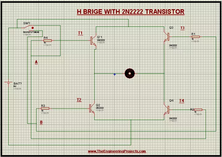
Introduction to H-Bridge
In electronic circuits, the direction of quantities like the flow of current, EMF, Electric field lines matter a lot. The H Bridge is used to control such motors through its specialized circuitry. The H Bridge is defined ...
Hey learners! Welcome to another exciting electrical experiment in Proteus. At the present day, we'll perform the inversion of voltage. For this purpose, we will use the implementation of Transformer as Step-up Transformer. Prior to start, let's have the basic information about the 12V to 220V Step up inverter using Transformer in Proteus. In this tutorial, we'll learn:
What is a 12V to 220V inverter?
What is the function of the transformer in the 12V to 220V inverter?
How can we implement the Step up inverter using a Transformer in Proteus?
What are some applications of the 12V to 220V inverter?
Moreover, there will be some useful pieces of information in DID YOU KNOW sections.;
12V to 220V inverter
In electronic appliances, the circuitr ...
Hello Engineers! Welcome to the board. We hope you are having a good day. In this tutorial, we teach you about Pulse Width Modulation. We'll discuss some important points about the topic. Let's have a look at the Topics of the tutorial:
What is Pulse Width Modulation?
What is 555 Timer?
how does 555 Timer is used in the Pulse Width modulation circuit?
How do we design the circuit of Pulse Width Modulation in Proteus ISIS?
In addition, you will have some useful information bout Pulse Width Modulator in DID YOU KNOW section.
Pulse Width Modulation
Pulse width Modulation is a useful technique in the world of Modern Electronics. Let's have a look at the information about Pulse Width Modulation.
Abbreviation of Pulse Width Modulation
The Abb ...
Hello Pupils! I welcome you to the board. I hope you are fine. In today's tutorial, we will design a project Metal Detector using 555 Timer in Proteus ISIS. All of us perceive the situations when at the public places such as on airports or in shopping malls where sharp metallic objects such as a knife or illegal guns or even a nail cutter are not allowed, there are walkthrough gates at every entrance so that any person with the forbidden material when passes through the gate, the alarming buzzer automatically switched on. This happened because the walkthrough gates have the Metal Detector circuit in them that works immediately when such a situation occurs.
In this session, we'll learn:
What are Metal Detectors?
How does the 555 Timer collabor ...
Hey Geeks! Welcome to The Engineering Projects. We hope you are having a reproductive day. We know that sirens are the special sounds that are the symbol that something unusual is occurring or about to occur. You may have experienced the Siren of the Walkthrough Gates at the airport when a person having the knife or other forbidden material pass through it. Or you have heard the Siren of the ambulance and seen that all the traffic gives the way to the ambulance when they hear the special Siren of the Ambulance. The same is the case with the police Siren.
The Police sirens are the special sound and it is set with the help of 555 Timer Integrated Circuit. You will learn how can one design a Police siren using the 555 Timer circuit in this tutorial. ...
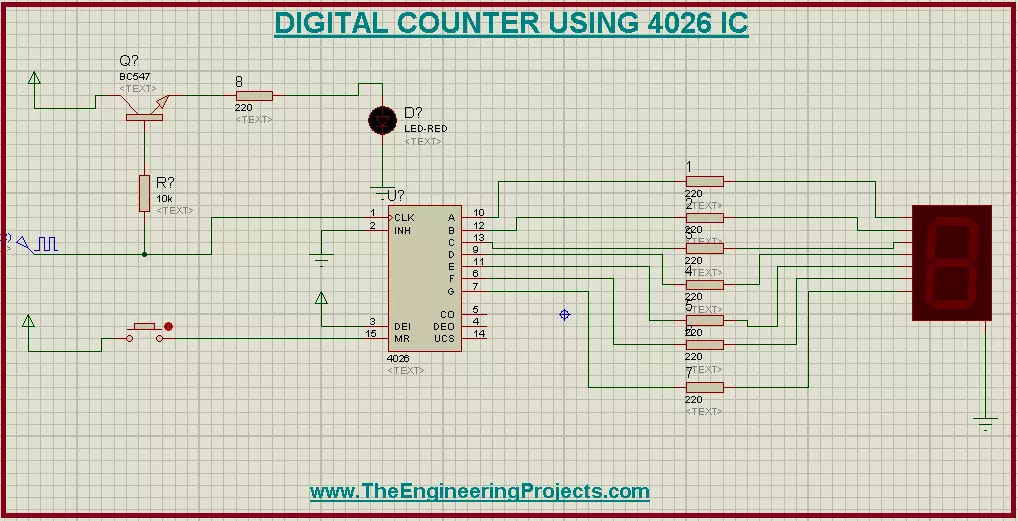
Hello Mentees! Welcome to the board. We hope you are doing great. We are working on another interesting yet easy Project in the Proteus ISIS and that is Digital Counter using 4026 IC in the Proteus. Counters are used in thousands of electronic experiments as well as in our daily life. Who is not5 familiar with Digital Watches and calculators. At the same token, the counters are used in the digital display microwave ovens and many household appliances as well.
In this session you will find the answers to the following questions:
What is 4026 IC?
What are Digital counters using 4026 IC?
How does Digital Counter using 4026 IC works?
How does we design the circuit of the Digital Counter circuit using 4026 IC in Proteus ISIS?
How can you con ...
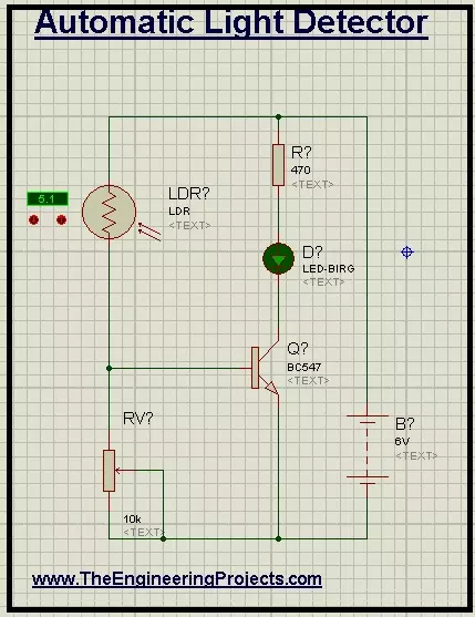
Hello Learners! We hope you are fine. Welcome to The Engineering Projects. The Automatic Light Detector is the device that automatically senses the light incident on it. Let's have a glance about the main points of discussion:
What is Automatic Light Detector?
What are different components and their functions in the Automatic Light Detector?
How does the circuit of Automatic Light Detector works?
How can we implement the circuit of Automatic Light Detector in Proteus ISIS?
Moreover, you'll have some chunks of interesting information in DID YOU KNOW sections.
Automatic Light Detector
Automatic Light detectors or automatic Light sensors are interesting devices. They have special mechanism in their circuit that senses the density of the ligh ...
Hi Friends! Glad to have you on board. In this post today, we’ll cover How to Download Proteus Library of Arduino Modules.
If you are a regular reader of our blog, you must have noticed that we are sharing Proteus Libraries of different embedded sensors & modules on regular basis. Moreover, we have also launched version 2.0 of few libraries. So, today I am going to provide links to download Proteus Library of all Arduino Boards designed by TEP.
So, let's get started with How to Download Proteus Library of Arduino Modules:
Download Proteus Library of Arduino Modules V2.0
It's the most advanced version of Arduino Proteus Library and consists of 6 Arduino Boards in total, named as:
Arduino UNO
Arduino Mega 2560
Arduino Mega 1280
Ardu ...
Hi Everyone! Glad to have you on board. In this post, we’ll cover the Arduino Pro Mini Library for Proteus V2.0.
I have already discussed its previous version i.e. Arduino Pro Mini Proteus Library V(1.0). I keep getting bug reportings from our blog readers (for previous versions), so I have tried to remove these bugs in this newer version. But if you still find any bug/error, you can approach me in the section below.
We have already shared many Proteus Libraries for Embedded sensors and these days we are trying to improve their versions.
First, we will download this library in zip format and then will use it in our Proteus software to simulate Arduino Pro Mini.
Before we go further, first we’ll detail what is Arduino Pro Mini.
What is Arduino ...
Hi Everyone! Glad to have you on board. Today, I am going to share a new version of Arduino Mega 1280 Library for Proteus V2.0. I have already shared its previous version i.e. Arduino Mega 1280 Proteus LibraryV(1.0). I have recevied many bug reportings from engineering students(for previous version), so I have tried to improve its performance in this newer version, but still if you find any bug/error, use the comments section.
We have already shared numerous Proteus Libraries of Embedded sensors and these days, we are in the the process of upgrading their versions.
First, we will download Proteus library zip file and then will add it in our Proteus software to simulate Arduino Mega 1280. Before moving further, first we’ll learn what is Arduino M ...