Solar Inverter in Proteus

Hello student! Welcome to The Engineering Projects. We hope you are doing good. We are glad to introduce and use the Solar Panel Library in Proteus. We work day and night to meet the trends in technology. This resulted in the design of new libraries in Proteus Software by TEP and today we'll talk about the project based upon one of our library i.e, Solar Panel.

Solar Panels work very great in this era when all of the scientists are working to have a power source that is cheap, environmentally friendly, and clean. Solar energy fits in all these dimensions. We are designing a solar inverter in our today's experiment. This inverter is the best idea for the engineering project because it has endless scope, it is easy and trouble-free. In this report, you will learn:

  1. What are solar inverters?
  2. How do we add the Library for Solar Panel?
  3. How does the circuit of the Solar Inverter works?
  4. What is the procedure to design a Solar inverter in Proteus ISIS?

In addition, we'll look at some interesting points in DID YOU KNOW sections.

Solar Inverters

The inverters are the devices that convert the DC power to AC power. These inverters are indispensable because a large number of electronics works on AC and the cons and pros of AC or DC device depends upon the requirement of the device. In this way, we may define the solar inverters as:

"The solar inverters are the devices designed to convert the solar energy stored in the solar panel in the form of Direct current, into the alternating current by the mean of its circuit." 

The energy is stored in the form of solar energy that comes directly from the sun. This makes it suitable to use for thousands of devices and users can get the ultimate solution of the power source with minimum or no cost once set up is completed.

DID YOU KNOW?
  • The solar panels are also called the photovoltaic module and these are made by the photovoltaic cells that store the energy coming from the sun and convert it into the direct current.

Addition of library for solar panel

As we said earlier, the idea of the Solar Panel lin=brary is new. We design this library to improve the experimentation and many circuits are been design by using solar energy and solar system. When you search for the "Solar Panel", you won't have this. In order to have it in your Pick Library option, just download it from our site. You can add it in really straightforward and easy steps:

  1. First of all, you need to download the zip file of the Solar Panel Library for Proteus.
  2. From the downloaded folder, unzip the library files into the Library folder of the Proteus.

You can also read the full description if you have any confusion about the installation.

Components of the Solar Inverter

The Solar Inverter consists of some simple passive components such as resistors, capacitors, diodes etc. along with other components. Out of which,  some of them are important to discuss. Just have a look at them:

 Solar Panel

Solar Panels are the best source to produce electricity. The Solar cells work when the sunlight strikes the surface of the Solar Panel, the photovoltaic cells capture the sunlight and convert them into another form of energy i.e. electric current. This energy is then stored in the battery or can be used directly to run the devices.

DID YOU KNOW?
  • In solar panels, the collection of the photovoltaic Module is called PV Panel.
  • On the other hand, the system of PV Panel is usually called an array.

Battery

We all know a battery is used to power up the components in the circuit. yet, in our circuit, the battery will be used to store the energy produced by the solar panel. This process continues until the switch is opened. Once the switch is opened, the battery will be used to run the inverter.

Relay in Solar Inverter

The relay is an engrossing component. It works as the controller of the circuit. The working of the relay seems like the switch but it has a magnetic coil in it that magnetizes and de-magnetizes, according to the requirement of the user. This plays an important part in the charging and discharging of the battery as well as the working of the Solar Panel.

Working of Solar energy Inverter

The Working of the solar inverter starts when the user plays the simulation. In this case, we always assume that the direct sunlight is striking to the solar panel and it is producing energy. We can say, the circuit of the solar inverter consists of 2 mini circuits connected with each other.

  1. The circuit of the solar panel is the medium of energy.
  2. The circuit of the battery absorbs the energy coming from the solar panel and releases the energy when the user requires it.

Both of the circuits are joined and disjoined with the help of switches. As far as the switch of the Solar Panel is closed, the circuit does not show any output. When the switch is turned closed(connected) then the energy from the solar panel starts moving towards the relay.

  • The Relay is magnetized and it produces the path for current to flow towards the battery and charge it.
  • In this mode, if the switch of battery is opened, the LED does not show output, but the battery still charges.
  • If the switch of battery is closed, the battery is getting charged and shows the output at a time.

One can stop the charging process by switching the solar panel off. The output of the battery will still be seen because of the charging process until the battery has the energy.

Simulation of the Solar Panel Inverter in Proteus ISIS

To simulate the circuit of the Solar Panel Inverter, go along with these steps:

Material Required

  1. Solar Panel
  2. Diode
  3. Transformer
  4. LED
  5. Resistor
  6. Capacitor
  7. Switch
  8. Battery
  9. Ground
  10. Connecting Wires

Procedure for the Solar Panel Inverter Simulation

  • Fire up your Proteus Software.
  • Create a new project.
  • Go to the "P" button and choose the 1st eight elements given in the list above.
  • Arrange all the components one after the other on the screen.
  • At this time, we are going to change the values of some components.
  • Change the value of R1=1K, R2= 18, C1=470uF,Battery=9V.
  • Connect the components with one another by following the image given next:
  • You can see in the image, the red-colored wire shows the voltage and the arrows are indicating the flow of current when both the switches are closed.
  • You will notice, as soon as you play the button, the terminal of the Relay changes its position.
  • The lights of the LEDs indicate the working of the circuit of the Solar power inverter.

Consequently, we saw about the theory and the practical performance of Solar inverters in Proteus ISIS and we learned how can we add the library of solar panels in the Proteus.

555 Timer TV Remote Control Jammer in Proteus

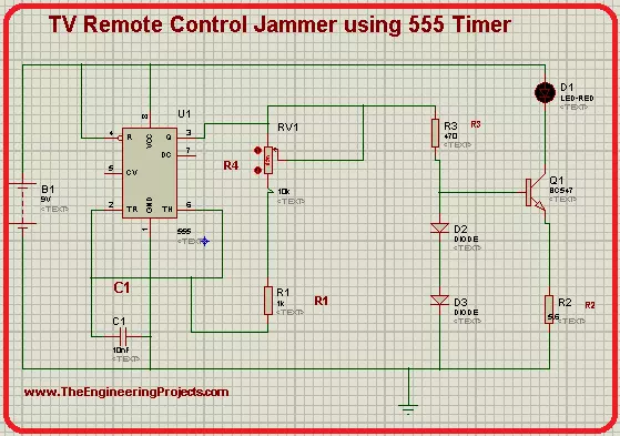
Hey pupils, welcome to The Engineering Projects. We hope you are doing great. In today's simulation in Proteus ISIS, we'll seek the knowledge of an interesting topic. We are going to design a Television remote jammer in Proteus. We all are familiar with the TV Remote controller device and know it works when a light signal emitted by it is sensed by the television. Have a glance at the topics we will see in detail today:

  1. Introduction to 555 Timer TV Remote Control Jammer.
  2. Components of the circuit.
  3. Working principle of 555 Timer Jammer.
  4. Simulation of the Jammer of TV Remote Control using 555 Timer.

Moreover, you will also learn some interesting facts about the topic in DID YOU KNOW sections. let's jump to our first topic.

555 Timer TV Remote Control Jammer

Remote controls do not require any introduction. We all use many types of remote controller devices in our daily lives. The TV Remote controls work on the principle of Infrared light. Yet, what if we do not want to give any access to other users or there is a requirement of blocking the signals from the remote controller device. In this case, jammers are useful because they do not alter any functioning of remote controls and just distract the television to sense the light signals. On this basis, we define the 555 Timer TV Remote Control Jammer as:

  • The 555 Timer TV Remote Jammer is a device used to jam the Infrared Lights emitted by the remote control, by producing a constant pulse of signals and distract the remote controller signals.

Before starting the working of the TV Remote control Jammer, let's have a piece of quick information on how does the TV Remote works. When we press the button of the remote, it sequentially emits the pulses. These pulses are then received by the IR Reciever present in the Television. Each time, every button has its own frequency of pulses so that the IR Reciever can sense which button is pressed. Then the TV act according to our command.

Now, in the case, when we want to cease the television to sense these signals, we just create a pulse, more powerful than TV remote controller, to disturb the pulse from the TV remote controller, so that the TV will not be able to sense pulses from TV Remote. We'll find how does this works in a bit.

DID YOU KNOW?
  • In electronics, the Jammer is any device that is used to prevent the instruments to sense the signals, waves or other mediums to cease their response.

Components used in TV Remote Jammer

In our circuit, we are going to use different components such as diodes, resistors, capacitors, etc. Out of them, 555 Timers and transistors are important to understand.

555 Timer in TV Remote control Jammer

The 555 Timer is an excellent Integrated circuit used in thousands of electronic circuits. It is used to transmit the pulses and control the flow of the circuit. The main reason behind its large number of projects and circuits is its modes. Basically, the 555 Timer can be used in three modes:

  • Astable Mode
  • Bistable Mode
  • Monostable Mode

For our circuit, we'll go for Astable Multivariable mode. This mode is chosen so because the IR waves from the remote control have very specific wave frequencies. In this way, when the waves from TV control Jammer will be Astable, this will be better to distract the TV from the remote's pulses. The 555 Timers is an 8 pin IC. In our circuit, pin 5 and pin 7 of the 555 Timer will remain unconnected. Other pins will be connected according to their respected functions.

Transistor in Remote Control Jammer

It's an NPN Transistor with three terminals called Emitter, Collector, and Base Terminals. In our experiment, the BC547 transistor will be used. The transistor will act as an amplifier in the circuit to make the pulses generated by the 555 Timer more clear, strong, and effective.

Complete List of Components required

  1. 555 Timer IC
  2. Resistor
  3. Diode
  4. Capacitor
  5. POT HG
  6. LED
  7. Battery
  8. BC547
  9. Ground Terminal

Working of TV Remote Control Jammer using 555 Timer

  1. The working of the circuit starts when the 9V Battery starts its work.
  2. This power enters 555 Timer through its two pins. The 555 Timer, in our case, is in Astable mode.
  3. In this way, the 555 timer generates a pulse that is not stable.
  1. To make the pulses more strong and effective, we use the Transistor. The transistor here works as an amplifier and amplifies the pulses coming towards it through its base terminal.
  2. The output of 555 Timer IC then passes through a couple of Diodes that are connected to the base and Emitter terminal of the BC547.
  3. Ultimately, the pulses of the 555 Timer IC pass through the LED and then to the collector Terminal of the Transistor.
  4. The LED shows the speed of the output pulses.
  5. This abrupt pulse is enough to distract the Infrared Reciever of the Television.
  6. So, as a result, we get a strong pulse of 36KHz-38KHz carrier frequency,

TV Remote Jammer circuit using 555 timers in Proteus

The simulation of the circuit is easy if you follow the steps given below carefully. So Let's go ahead.

Procedure to design circuit of TV Remote Jammer

  • Excite you Proteus Software and start a new Project.
  • Hit the "P" button then choose the first 8 components from the window that appeared.
  • Now arrange all the chosen components on the screen by following the image given next.
  • Go to the left side of the screen>Termnals mode>Ground and attach this ground terminal below the circuit.
DID YOU KNOW?
  • The mode of 555 Timer is identified by the components and their manner of connection with 555 Timer.
  • You can change the frequency of the pulses by changing the values of the components.
  • This change can easily be detected by observing the speed of the power entering the LED.
  • To connect them, let's use connecting wires.
  • You can alter the values of some components as:
POT HG: 1K, R1: 1K, R2: 5.6, R3:470, C:110nF,Battery:9V.
  • Go to virtual instrument Mode>Oscilloscope and fix it with the LED's output.
  • Finally, at the present moment, we are going to simulate our circuit.
  • Click on the play button and set the values of voltage and frequency through nobs.
  • The output of the oscilloscope will show that waves are formed frequently.

In the end, we conclude that we can design the circuit of the TV remote control jammer using the 555 Timer in Proteus. We had a short introduction to how does TV Remote works, we saw how can we jam its signal, we found how does the circuit works and at the end, we design a full circuit of a TV remote control jammer with the help of 555 timers in Proteus ISIS. This circuit emits a constant bit of 1.775 meters per second and the frequency ranges from 36KHz to 38KHz.

Traffic Light Circuit using 555 Timer in Proteus

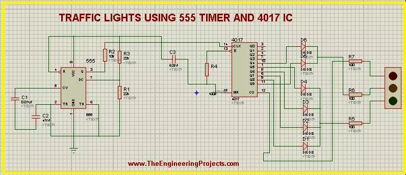
Hey pals! Welcome to the board. We are talking about a fascinating experiment about The Engineering Projects. We all know about the Traffic Lights. But today, we'll see inside the Traffic Lights and find some interesting working of the circuit of Traffic Lights. Before this, just have a look at the topics of discussion:

  1. What is the Traffic Lights circuit with 555 Timer?
  2. What does the 555 timer do in Traffic Lights?
  3. What is the purpose of the 4017 IC Counter in the circuit?
  4. How does the circuit of Traffic Lights work with 555 Timer IC?
  5. How can we perform experiments with the circuit of 555 Timer Traffic Lights in Proteus ISIS?

In addition, we'll see some important points about the topic in DID YOU KNOW sections.

Traffic Lights circuit with 555 Timer

Whenever we rush toward any road that has a heavy flow of vehicles, we always follow some traffic rules. One of the most fundamental traffic rules is to follow the traffic lights. These traffic lights direct the vehicles to start or stop moving at the road according to our turn. These turns are decided by the Traffic Lights. The traffic Lights show the different colored lights and these lights turn on and off in a sequence. We know all these things, but we are revising these to get the logic behind the scene. we define the Traffic Lights technically as:

"The traffic lights are the combination of three LEDs colored as red, amber and green that are connected in a specialized circuit that gives the output from the LEDs in a specific format and this format is used to control the flow of traffic."

These LEDs are enclosed in a metallic body. Traffic Light signals are so useful that 99% of the countries use them. This makes the circuit one of the most fundamental and common circuits to understand.

There are many devices through which the Traffic Lights may be controlled. Out of which, two are common:

  1. Traffic Lights with the D Flip Flop.
  2. Traffic Lights with 555 Timer

We have discussed the 1st method in our previous tutorial, Let's have a look at the next one.

555 Timer IC Performance in Traffic Lights

before starting the simulation, let's have a look at its components briefly. The circuit of Traffic Lights uses a very common yet powerful device i.e, 555 Timer IC. The 555 Timer is so useful that it is said that annually, a billion of 555 Timers are produced and it is considered as the most popular IC of the year 2017. We introduce the 555 Timer as:

"The 555 Timer is a common 8 pins Integrated Circuit used in a variety of oscillation generators and Timers to generate a pulse of the signals that control the output sequentially."

In our experiment, we'll apply the Mono-stable Multi-vibrator mode of the 555 timer. The output of 555 Timer in this mode is in the form of a single pulse of current that has a specific length. This pulse is sometimes called the one-shot pulse.

4017 IC in the 555 Timer Traffic Lights

The 4017 is the special IC that is usually coupled with the 555 Timer. It works on the pulse generated by the 555 Timer and the definition for the 4017 IC is given as:

  • "The 4017 is 16 pins counter and decoder of 555 Timer IC that generates a decade counter output from its output pins and the outputs advances from one to another with the positive edge of the clock pulse."

Once the clock pulse of 4017 IC in the traffic Lights goes from low to high, the IC started its cycle again and we get a sequential Logic output. The pins 3 to 12 of the 4017 IC Counter are said to be the output pins of the 4017 and we'll connect the traffic lights with them.

Working of Traffic Lights using 555 Timer IC

  1. The Working of the circuit starts with the power connected to the Vcc terminal of 555 Timer IC.
  2. the power in the 555 Timer in Mono-stable Multi-vibrator mode produces a uniform pulse of current that is stabilized with the help of capacitors used with the 555 Timer IC.
  3. The current is then fed into the clock terminal of the 4017 decade counter IC that decodes these pulses of 555 Timer IC and produces the stream of output at its output terminals.
  4. The terminals of the 4017 IC are connected to the diodes in a specific manner. These diodes conduct the electricity on only one side and so that a specialized sequence of the current is found at the outputs of these diodes.
  5. There are two sets of the diode connections. Four diodes are connected in a set and two in another. The output of 1st set is fed to Green Light of the Traffic Lights. The Amber and Red lights of the circuit are connected with the second set.
  6. The output of these two sets is connected with the resistor and then finally this current passes to the traffic Lights signal.
  7. In the end, we get a specialized, clear and automatic output from the traffic lights.

Simulation of the circuit of 555 Timer Traffic Lights in Proteus ISIS

At the moment, we are going to design the circuit of the experiments. So let's start.

Devices required for 555 Timer Traffic Lights

  1. 555 Timer IC
  2. 4017 IC
  3. Capacitors - 3
  4. Resistors - 7
  5. Diodes - 6
  6. Traffic lights
  • Fire up your Proteus Software.
  • Choose the material from pick Library through "P" button.
Let's divide the circuit design into three parts:
  1. 555 Timer connections
  2. 4017 IC Counter connections
  3. Connection of 555 Timer and 4017 IC

555 Timer Connections

  • Choose the 555 Timer from the component's area and arrange it on the left side working area.
  • Select the resistor then  arrange three resistors with pin 3, 6 and 7.
  • Take capacitor and set two capacitors with pin 2 and 5 of 555 Timer.
  • Go to terminal mode and set a Ground terminal at the Ground pin of the 555 Timer.
  • Connect all the components of 555 Timer IC as:

Connections of 4017 IC

  • Go to components, choose 4017 IC.
  • Select diode and arrange the 7 diodes with the output pins on the right side of 4017 IC.
  • Take care with the direction of the diodes.
  • Set a resistor between the pins 13 and 16 of 4017 IC.
  • Arrange three resistors  just after the diodes.
  • Now set a Traffic Light signal on the right side of the resistors.

DID YOU KNOW?????????????????????????????

It is said by AAA, the average American spends 58.6 hours every year waiting at the red light of traffic signal.
  • The circuit now looks like the image given next:

Connection of ICs

  • Now, at the moment, we'll connect the ICs to finally set our circuit.
  • Set a capacitor between both these ICs.
  • Alter the names of the components by given them numbering so that Proteus may distinguish between different Resistors, Capacitors, diodes and ICs.
  • Change the values of each component according to the table given next:
Component Values
C1 0.01uF
C2 47uF
C3 6.8nF
R1 23k ohm
R2 10k ohm
R3 22K ohm
R4 100k ohm
R5 100 ohm
R6 100 ohm
  • Observe deeply the image given below and connect all the components with the help of connecting wires.
  • Our circuit is now good to go, Let's tap the play button and simulate the circuit.
The circuit shows the required output well. If you found any error, look at the steps given above again.

DID YOU KNOW????????????????

The working speed of the Traffic Lights can be varied by changing the values of capacitors connected with  pin 5 and 2 of the 555 Timer IC.
So, today we saw a fantastic circuit in which we learned that what are the Traffic lights signal using 555 timer, how does the ICs of 555 timer and 4017 IC Counter work with each other to show the output of the Traffic Lights and we designed the circuit of 555 Timer Traffic Lights in Proteus ISIS. If you have any questions, you can contact us through the comment sections.

Simplest LM386 Audio Amplifier in Proteus

Hey Learners, welcome to another exciting tutorial about electronics. We are talking about an audio amplifier using LM386. This is a very simple IC that we are going to used for the amplification of the audio signals. We shall go through the core postulation about the topic and then work on the practical implementation of the experiment. Just have a look at the topics of discussion:

  1. Introduction to LM386 Audio Amplifier.
  2. Components of LM386 Audio amplifier.
  3. LM3386 Audio Amplifier Working.
  4. Simulation of the LM386 Audio Amplifier Circuit in Proteus.
In addition, you will find interesting information in the DID YOU KNOW sections.

Introduction to LM386 Audio Amplifier

Audio signals play important role in many devices. These signals are used to regulate the life of the community in many ways. These signals, when required, are amplified by some means to use them more effectively and efficiently. Many devices can do this task. Yet, at the present time, we are going to discuss LM386 Audio Amplifier. Let's have its definition:

  • "The LM386 audio frequency Amplifiers are the types of low power audio amplifiers used commonly in small amplifier systems and can be run on even a 9V battery."

The input signals once pass through the LM386, are amplified and the user senses a loud sound as compare to the input signal. This type of amplification is really important in the circuits where a signal is required to show the completion of the task, requirement of the involvement of the user or an error in the circuits.

Components of the circuit of LM386 Audio Amplifier

In this article, we're using the very simple circuit of LM386 Audio Amplifier to show the easy but understanding hypothesis of the topic. This circuit consists of capacitors, audio signals, LM386 IC, power source and speaker, out of which, we have to discuss the LM386 IC, Audio signals and speaker.

LM386 IC

The LM386 is a versatile chip that can easily be used in many kinds of circuits. The IC  runs no low voltage, therefore it is a very common yet power operational amplifier that is used even in DIY guitar pre-amplifiers. If we look at the basic definition of LM386 then we find:
"The LM386 is an 8-pin Dual inline integrated circuit that can work on very low voltage and when connected with some simple components can be used as an operational amplifier in a large number of amplifying circuits."
The power intake and efficiency depends totally upon the models of the LM386. Basically, there are three models of aLM386 IC as mentioned below:
Number of Pin Name of pin
1 Gain
2 Negative input
3 Positive Input
4 Ground
5 Gain
6 Bypass
7 Input power
8 Output of IC
Being an op-amp, the LM386 has a very basic task. The IC gets the power from its input terminals and using its circuitry, it amplifies the power output signal on the rate of tens, hundreds, thousands and so on. The total output purely depends upon the input and the model of LM386.

Speaker

The speakers are the devices that takes the audio signals and convert them into voice. This conversion is done by the special mechanism of speaker. In this experiment, the output will me hear with the help of this speaker.

Variable Resistor

As the name describes, the variable resistor is the special device that is capable of changing the value of resistance according to the requirement of the user. The + and - terminal of variable resistor are used to increase and decrease the resistance respectively. In this way, the input audio signals can be controlled.

Working of LM386 Audio Amplifier

  1. The working of the LM386 Audio Amplifier starts with the audio signal generation of audio generator.
  2. These signals passes through the capacitor that regulates these signals and then pass them to the LM386.
  3. The IC inputs these signals, the pin 6 of the LM386 is connected with the DC Source hence it powers it up. The IC now amplify the audio signals.
  4. From pin 5 of the IC, the amplified audio signals are generated. Meanwhile, the resistor and capacitor regulates the signal so that the user may sense these signals in the right sequence of waves.
  5. Finally, the speaker takes these signals as input and convert it in the form of sound so that the user can hear it easily.

Procedure to simulate the LM386 in Proteus ISIS

By availing all the information given above, let's simulate the circuit in Proteus ISIS. Just apply the instructions given below:

Material Required

  1. LM386 IC
  2. Resistor
  3. Capacitor
  4. POT HG
  5. Speaker
  6. Ground Terminal
  7. Audio device
  • Start your Proteus ISIS.
  • create a new Project.
  • Click on P button.
  • Choose 1st five components mentioned in the list given above.
  • Arrange all the components on the working area by following the image given next:
  • Go to Terminal Mode from the left side of your screen and choose ground. Now, set it just below the circuit.
  • Go to Generator mode>choose audio and set it just on left side of arrangement.
  • Double click the audio probe>brows>upload this file.
  • [audio wav="https://www.theengineeringprojects.com/wp-content/uploads/2021/06/file_example_WAV_1MG.wav"][/audio]
  • Change the values of the components as described in the following table :
Component Value
C1 1nF
C2 100F
C3 1uF
C4 47nF
C5 47 nF
C6 220uF
R1 10 ohm
R2 10 ohm
DC Power Supply 9V
 
  • Once all the values are changes, just go to virtual Instrument mode and select the oscilloscope above the components.
  • At this time, join the components with the help of connecting wires.
  •  Hit the Play button with your mouse and simulate the circuit.
  • Change the values of the voltages of terminals and current through the nobs to get the visible wavelengths.
one can see clearly that the output signal(blue waves) are more amplifier and strong than the input signals (Yellow waves).

Conclusion of experiment

The LM386 is the IC that can be used to amplify the audio signals. The input frequency and thus the volume of the sound amplifies and we can hear the loud sound. One can change the intensity of sound by using the active variable resistor.

RC Electronic Circuits Simulation in Proteus ISIS

Hello friends! Welcome to the Engineering components. Today, We are talking about the very common topic of electronic devices. In this tutorial, we'll pick very common components and learn about their role in circuits. If you are a beginner in the world of electronics, you must read this article till the end because we'll learn all the things from scratch till the completion of the circuit. In this article, you will learn:

  1. Introduction to electronic circuits
  2. Categories of electronic circuits.
  3. Introduction to Resistor and Capacitor.
  4. What are RC Circuits?
  5. Simulation of R Circuits in Proteus ISIS.
Let's look at the description.

Introduction to Electronic Circuits

We come across many circuits in our daily lives, some of them are electrical circuits and some are electronic circuits. There are many differences between them but the main difference is, that electrical circuits do not have decision-making capacity whilst electronic circuits do have this ability. In electronic circuits, we power up the components with the mean power source and get the output. Hence we may define the electronic circuits as:

  • "The electronic circuits are the types of circuits in which the individual electronic components are used that are connected to the power source with the help of wires so that the current can pass through the components."

The electronic circuits are also called discrete circuits because they are somehow, opposite to the integrated circuits. Most of the circuits use a combination of electrical and electronic circuits.

Categories of Electronic components

As we know, electronic components are used in many ways. For convenience, we divide the electronic components into categories. These are categories into two main sections:

  1. Active Components.
  2. Passive components.

The main focus of this article is passive components. The passive components include Capacitor, Resistor and Inductor. These are symbolized as C, R and L respectively. We'll learn about the first two of them today.

Introduction to Resistor and capacitor In electronic circuits

The Resistor and capacitor may be said to be the backbone of thousands of electronic circuits. To design a circuit, one should have a clear concept of these components. So, Let's have their introductions:

Resistor in Electronic Circuits

As the name implies, the resistor shows the resistance for the current in the circuit. It has a tube-like shape that has a molded figure and has a wire at the start and end. One may define the resistor as:

  • The resistor is a passive, bi-terminal electrical component that is used in the circuit to have the electrical resistance in the current. When we use it in electronic circuits, it reduces the sudden current flow in the circuits, biases the active elements, divides the voltages in the circuit and performs such other tasks.
Current is the flow of electrons, this flow should be resisted by some mean, so that the components used in the circuit will be safe from damage. To control this opposition, one must have a clear idea about the resistance. The resistance is the measure of the property of the resistor to oppose the current in a circuit. The resistance of the resistor is symbolized by the strip of different colors. Each color has a meaning of different value.

Capacitor in Electronic Circuits

The capacitor works like a battery. The body of the capacitor is so simple and easy to understand, yet plays an important role in many types of circuits. The introduction of Capacitor is given next:
  • The capacitor is an electrical component consists of two metallic plates and two wires connected with two plates that store energy passes through it in the form of an electrostatic field in between its two metallic plates. Its body is packed in an envelope.
As you can see in the picture, capacitors are manufactured in the form of a tube-like shape with two wires that are used to connect within the circuit. The capacitors are made in a variety of ranges according to their role in the circuit.

RC Electronic Circuits

As we know the Resistor is denoted as R and the capacitor is denoted by C. The RC circuits are the simple and easy circuits to understand.  We introduce the RC Electronic circuits as:
"The RC Circuits are the Resistor-Capacitor circuit in that consist of only resistor and capacitor as passive components of capacitor and these are connected with the current or voltage source according to the type of circuit."
One should keep in mind that we are talking about the category of passive components right now. Otherwise, some other components such as the power generating component are also used in the circuit. The are two categories of RC Circuits mentioned next:
  1. RC Series circuit.
  2. RC Parallel circuit.
RC Series circuits are the ones in which the resistor and capacitors are connected in series whereas, when we talk about the RC Parallel circuit, the R and C are connected in parallel to each other. RC circuits are also called the filter circuit or network circuit because many RC circuits are used to filter the unwanted frequencies of signals from the circuit and keep only the required ones. The RC Circuits are further classified on the basis of the number of components used in the circuit. The circuit is called the first-ordered RC Circuit if it contains only one resistor and one capacitor. Similarly, if it has two resistors and capacitors then the circuit is called the second ordered RC Circuit. To have a clear idea about the circuit, design it on the Proteus.

RC Electronic circuits in Proteus ISIS

To experiment, just follow the steps given next:

Required Components

  1. Resistor
  2. Capacitor
  3. Battery
  4. Connecting wires

Procedure

  • Start your Proteus software.
  • Click on the "P" button and choose the required components one by one.
  • Arrange these components in the working area.
  • Connect the components with connecting wires.
  • Play the circuit with the play button present on the lower-left corner of the screen.

This image shows two types of circuits. The upper circuit is the RC Series circuit and the lower circuit is the RC Parallel circuit. Hence today, we learned about the introduction of Electronic circuits, we saw what are RC circuits, their components and their types depending upon different parameters. We also simulated the circuits in Proteus.

Pure Sine Wave Inverter using 555 Timer in Proteus.

Hi Mentees! Welcome to another electronic tutorial about the 555 Timers. We are working on Proteus and in the present experiment, we'll design the circuit of Pure Sine Wave Inverter. Inverters are the opposite devices to rectifiers. We'll show you the meaning of this sentence in action Yet, before experimentation, we have to learn some predominant concepts about the experiment. So, We'll go through the following topics:

  1. Introduction to Pure Sine Wave Inverter.
  2. Components used in the circuit of Pure Sine Wave Inverter.
  3. Working of the circuit of sine wave inverter.
  4. Circuit simulation of pure sine wave inverter in Proteus.

Introduction to Pure Sine Wave Inverter

In electronics, we examine the output of devices in the form of waves. Basically, there are four types of waves including sine wave, sawtooth wave, square wave and triangular wave. The title of the circuit we are discussing today consist of two main concepts:

  1. Sine Wave
  2. Inverter

Let's recall them one after the other.

  • Sine Wave: The sine wave is a mathematical curve that is a smooth, s-shaped, periodic, continuous wave and is described as the graph of sin function indicated by Y=sin x.

The sine waves are used in Mathematics, physics, engineering, signal processing and other related waves. In Electronics, the sine wave indicates the AC.

  • Inverter: Inverters are the electronic devices that are used to convert the DC into AC. We can say, Inverters are the opposite circuits of rectifiers. The purpose of this inverter is the same.

Hence, when we combine these concepts, we get the following definition of Pure Sine Wave Inverter:

  • "The Pure Sine Wave Inverter is a circuit that takes the input in the form of DC and gives output as AC. It is used to run any type of instruments designed to run on smooth sine wave output."

We can make the circuit with the many methods, out of which two are:

  1. Pure Sine Wave inverter through MOSFET.
  2. Pure Sine Wave Inverter through 555 Timers IC.

The focus of this article is the 2nd type. So let's look at its circuit.

Circuit of Pure Sine Wave Inverter using 555 Timer

If you understand the working of its components, the circuit of the sine wave inverter is quite simple. It consists of some simple electronic components that every engineer uses many times. But out of them, 555 Timer and Transformer should be discussed here.

555 Timer

The 555 Timer is a great integrated circuit. It is used in thousands of circuits that have the requirement of pulses with uniform length. It is an 8 pin integrated circuit that may be used in three modes. In this tutorial, we'll use the 555 Timer in Astable Mode.

Transformer

A transformer is a passive electronic device that is used to transfer electrical energy from one source to another by the mean of electromagnetic induction. The main purpose of the transformer is to change the level of the input current (high or low) to the output current. The circuit of Pure Sine Wave Inverter is designed so, we provide the 12V DC as input and get the 240V AC as output. In addition to these, we will use Inductor, diode, capacitor, resistor and power source in our circuit.

Working of Pure Sine Wave Inverter using 555 Timers

  • The working of the Pure Sine Wave Inverter starts when the 12 volts DC is applied to the components.
  • These 12 volts enter the 555 Timer through pin 3 of the 555 timer that is in the Astable Mode. Due to this Mode, the 555 timer produces a single uniform pulse that is fed into the inductor.
  • Every time, when a new pulse enters the inductor, it stores the energy in the form of an electromagnet. In the time t, when this energy is fully discharged through the inductor, its signs of induction change. After that, a new pulse enters the inductor and this process goes on. This energy passes through the resistor and finally fed into the transformer.
  • In our case, the transformer is stepped high and it gives us the output of 240V AC. One can check this using AC Voltmeter.
  • The diode connected to pin 7 of 555 Timer passes the current in only one direction (because it is a diode) and sends this pulse to the transformer by the mean of a capacitor for a steady pulse.

Simulation of Pure Sine Wave Inverter in Proteus

Using all the concepts discussed above, let's get started with the simulation of the circuit by following the simple steps.

Required Devices

  1. 555 Timer
  2. Vsource (DC power source)
  3. Diode
  4. Capacitor
  5. Inductor
  6. Transformer
  7. Resistor
  8. Connecting Wires
  9. Ground Terminal

Circuit Simulation of Pure Sine Wave Inverter

  • Excite your Proteus simulator.
  • Start a new Project
  • Tap to the "P" button of the screen and choose 1st seven devices one after the other from the list of required devices.
  • Arrange all the devices on the screen by following the image given below:
  • Left click on the screen>Go to Place> Terminal>Ground and set it just below the circuit.
  • Change the Values of the devices according to the table given next:
    Components Values
    R1 1KR
    R2 1KR
    R3 0.02KR
    C1 1nF
    C2 100nF
    C3 100uF
    Inductor 1mH
    Transformer Primary= 1H, Secondary= 2000H
  • Go to Instruments>Oscilloscope and set it at the output side.
  • Connect terminal A with
  • Now connect all the components carefully with the connecting wires.
  • Click on the Play button just at the lower-left corner of the screen and start the simulation.
  • You will find the Sine Wave Inversion on the output screen of the Oscilloscope.
Truss, in the present article, we saw the introduction of Pure Sine Wave Inverter, Look at its devices and components, saw the working of the whole circuit and learned to design the circuit in the Proteus practically. We hope you learned well.

Diode: Definition, Symbol, Working, Characteristics, Types and Applications

Hello friends, I hope you all are happy, healthy, and, content. Today, our discussion is all about "Diodes". Whoever has been a science student, knows about diodes. Although it seems to be a tiny component of a circuit, apparently it is true but it has a lot of complexities or you can say, it's a storm in a teacup. You might have read a lot about diodes in physics, in today's discussion we would be moving step by step into the pool of diodes from definition to working of diodes, their types, and then lastly its applications. Let's get started!

Diode Definition

First things first, Let's define diode,
  • A diode is a basic discreet electronic component made up of semiconductor material, used in electronic circuits, which allows unidirectional current to flow through it, i.e it only conducts current in one direction.
  • You must be thinking, how is it possible for a device to conduct electricity in only one direction only, even when it has two terminals?
  • The answer lies in making of a diode, a diode has zero resistance in one direction, meanwhile, the other direction has infinite resistance, hence maintaining the flow in only one direction hindering the flow in other direction, but keep one thing in mind, its an ideal case, otherwise a little bit of current flow is always there and ideal cases do not exist!
  • A diode can act as a conductor and as an insulator as well. When the diode is reverse biased it acts as an insulator meanwhile when a diode is forward biased, it acts as a conductor.
  • Diodes are mainly made up of two famous semiconductors silicon and Germanium.
  • There are several different types of a diode, make of each one differs according to its function and the way it transmits current, don't worry we are going to have a detailed account of it soon.

Diode symbol

  • The above symbol represents a diode, it's the symbol for a basic diode, let me clear one thing for you, there are several different types of diodes that we would be studying next and each one is represented with a different symbol accordingly. So, do not doubt yourself when you see a slightly different one!
  • You can observe two ends or two terminals labeled as cathode and anode respectively.
  • The Arrowhead represents the anode and direction of current flow.
  • The other end is the cathode represented as a line attached to the terminal vertex of the triangle representing the anode.

History of Diode

Here is a brief account of the history of diodes, a little touch-up hurts no one!
  • So, the History of diodes dates back to 1900 when the thermionic diodes and semiconductor diodes were made for radio.
  • Vacuum tube diodes were the trendiest items of early 1950 being used and altered by several scientists through different experiments such as Fredrick Guthrie and Thomas Edison.
  • Fleming valve was the first recognized diode of its age with all the elements present in a diode in the true sense.
  • In world war ll, crystal diodes and Crystal rectifiers were used intensively in radar systems which led to extreme usage and development in the diode world, all thanks to their wide window of utility.

Working and Construction of Diode

In order to understand the working of a diode, let us first discuss its basic structure, how would you understand the working until unless you understand the make and build of a thing!

The basic structure of a Diode

  • A basic diode is made up of a semiconductor, a p-type semiconductor and an n-type semiconductor joined together. Do you have a basic idea of semiconductors? Semiconductors are materials that have properties lying within the spectrum of metals and nonmetals, you can read our detailed article on the periodic table if you want to know more about the elements and their respective properties.
  • Anyhow, we were talking about semiconductors, semiconductors are of two types, Intrinsic semiconductors, and extrinsic semiconductors.
  • Intrinsic semiconductors are pure semiconductors without any additional impurity. They include silicon and germanium.
  • Extrinsic semiconductors are the ones with doping, don't worry we are about to discuss it next.
  • I hope you have a general idea about p-type and n-type semiconductors, if not, we have got you covered. Read the next section for details;

Doping in Semiconductors

To understand p-type and n-type semiconductors, you must be aware of the concept of Doping. We can define doping as; Doping is the intentional addition of impurities into an intrinsic semiconductor. It changes the physical, electrical, and optical characteristics of that very intrinsic semiconductor.

1. p-type semiconductors

  • A p-type semiconductor is made by doping i.e adding an impurity which is an electron acceptor by nature into the semiconductor i.e gallium and boron are added to the silicon, turning it into a p-type semiconductor.
  • You must be thinking about why they are called p-type semiconductors? Let me tell you, The name p-type is given due to the presence of a positive charge on the semiconductor.
  • The p-type semiconductor contains a majority of holes and a minority of electrons.

2. n-type semiconductors

  • The n-type semiconductor is made by doping the semiconductor with an electron donor element.
  • The n-type semiconductor has a majority of electrons and a minority of holes.
  • The name n-type is given due to the negative charge of electrons present in the semiconductor, you knew that already, or you didn't?
  • Arsenic and phosphorus are used for the doping of silicone making it a n-type semiconductor.
Now we are done with the basics of n-type and p-type semiconductors, let us discuss their utility in making a semiconductor diode. The following section includes a breakdown of components and concepts lying in the scope of diodes.

PN junction

  • Our discussion would be incomplete without the PN junction, can you think of a diode without it? Yes, there are a few exceptions but typical ones necessarily have a PN junction.
  • As I have told you earlier semiconductor diodes are made up of n and p-type semiconductor materials joined together to make a diode.
  • The merger of these two materials is responsible for the making of PN junction made between the contact point of two materials.
  • After the formation of the PN junction, the process of diffusion takes place, we would be discussing it next, don't worry!

Depletion Region

  • There is a considerable difference between the amount of holes and electrons on both sides. If you know about the simple concept of diffusion, a particle moves from the area of higher concentration to the area of lower concentration and vice versa, same happens here, the holes from the p side move to the n side of the diode.
  • Meanwhile, electrons move from the n side where they are higher in concentration to the p side where they are lower in concentration.
  • This movement of electrons and holes generate a diffusion current leading to the formation of an immobile layer of positive and negative ion on the PN Junction, this layer is called depletion region.
  • Now you must be thinking why I'm telling you about the depletion region? Why is it necessary?
  • The depletion region limits the diffusion of electrons and holes from the opposite doped semiconductor portion, otherwise, after the constant diffusion, all the electrons and holes would have been diffused into each other leaving behind almost no charge carriers to conduct the current when the diode is connected to the battery.
  • On the other hand, the size of the depletion region maintains the current flow and resistance. Larger the depletion region, the Larger the resistance. You will understand this concept more easily once we would be done discussing the forward and reverse biasing of the diode and characteristics of the diode. Stay tuned!

Biasing conditions of the Diode

To understand the working of a simple diode, you must know about the biasing conditions of the diode first,
  • Forward biasing

  • Reverse biasing

  • Zero biasing

1. Forward Biasing

  • When the positive terminal of the battery is connected to the p-type semiconductor meanwhile the n-type semiconductor is connected to the negative terminal of the battery it is called forward biasing of the diode.
  • The depletion region is very thin in this case and it is easier for the forward Voltage or VF to overcome the depletion region for conduction of current.
  • PN junction offers very little resistance to the current flow due to the thin depletion region.
  • In forward biasing condition, an ideal diode has zero resistance, but as I told you earlier, an ideal condition does not exist.

 2. Reverse Biasing

  • In reverse biasing condition, negative terminal is connected to the p-type region of the diode, meanwhile positive terminal is connected to the n-type region of the diode.
  • The depletion region in this case is very thick.
  • The PN junction in reverse biasing offers a very high resistance due to the thickness of the depletion region.
  • A diode in ideal condition when reverse biased has infinite resistance.

3. Zero biasing

  • Voltage has not been applied to the diode, in zero biasing condition.
  • In zero biasing conditions, there is a thermal equilibrium in the diode.
  • The natural potential barrier is present in the diode, which is 0.5V to 0.7V for silicon and for germanium this potential barrier is 0.3V.

Characteristics of diode

  • We have already learned about the forward and reversed biased condition of the diode, in order to understand the current and Voltage characteristics of both the conditions , consider the following graph consisting of a single characteristic curve.
  • The voltage is usually plotted on the x-axis of the graph meanwhile the current takes the y- axis.
  • The starting point of the graph can be seen in the center, where both the values i.e current and the voltage is zero.
  • Forward current can be observed extending upwards, above the horizontal axis meanwhile, reverse current extends downwards.
  • In the upper right corner you can see the combined values of forward voltage and forward current.
  • The lower left corner shows the combined value of reverse current and reverse voltage.

Forward Characteristic of Diode

  • We have already studied about the forward biasing of the diode, forward characteristic corresponds to that.
  • In forward characteristic the current IF flows in forward direction and depends on the amount of forward voltage VF.
  • The relationship between VF and IF is called IV characteristic of diode or ampere volt relationship, this is the point of focus of our discussion!
  • When forward voltage is zero i.e
  • 0V, the forward current IF is also zero i.e 0mA.
  • From the graph we can clearly see that the increase in forward voltage , VF causes can increase in forward Current IF, when the value starts from the point 0 of the given graph.
  • Now its the turn for the most important point of the curve, the knee voltage denoted as VK.
  • You must be thinking why we call it knee voltage? And how is it achieved? Have a look at the line formed , it seems like an extended knee, so we call it knee voltage. Knee voltage is the point where forward voltage VF is large enough to overcome the depletion region of the diode and there is surge in forward current IF, marking the highest point of voltage, knee Voltage VK.
  • Knee voltage varies from material to material i.e VK is material specific.

Reverse Characteristic of Diode

  • During the reverse biased condition, a very little current is conducted by the diode.
  • You can observe the Reverse Voltage and Reverse current in the graph, represented by VR and IR respectively.
  • There is a very little amount of charge carriers which conduct the reverse current IR.
  • We cannot observe a considerable increase in Reverse current IR even with a large amount of Reverse Voltage VR.
  • VBR is one of the most important characteristics of the reverse biased diode, its the breakdown voltage of the reverse biased diode which refers to the amount of voltage at which the reverse current IR increases rapidly breaking the PN junction.

Diode Equation

Following equation refers to the ideal condition of the current and voltage of a diode either in forward biased or reversed biased condition; The equation corresponds to the following things;
  • I is the diode current sometimes represented as ID as well.
  • IS is the reverse bias saturation current and is not constant for any device, it usually varies with temperature.
  • VD is the voltage across the diode
  • VT is the thermal voltage which is equal to 25.8563 mV at 300 K.
  • In other conditions, Vt equals Boltzmann's constant × temperature ÷ electron charge i.e kT/q
  • n is the ideality factor, also called the quality factor and emission coefficient.
  • The equation is called Shockley ideal diode equation in which the ideality factor is preset to 1.
  • In other conditions, the ideality factor can range from 1 to 2 or maybe higher than that in some cases.
  • In forward bias condition, the ideality factor is almost negligible and the equation can be written as;

Types of Diode

With the advancement in technology and increasing human needs, diodes also changed shapes and took over several functions, there are several types of the diode, some of them are explained below;

1. Zener Diode

  • It is a heavily doped PN junction diode that works in a reverse-biased condition when a certain specified voltage is reached, this voltage is called Zener Voltage.
  • The Breakdown voltage marks the best possible functional capacity of the diode.
  • Zener diode is used for voltage regulation, you may observe one in clipping operations, circuit protectors, surge suppressors, and switching applications among the countless other uses which can not be listed here at once.
  • They are available in different zener voltages and can be used according to the need.

2. PIN diode

  • A PIN diode is a semiconductor diode having a wide undoped semiconductor region sandwiched between heavily doped n-type and p-type regions.
  • PIN photodiode doesn't rectify or distort the signal.
  • They have a wide range of applications being used in microwave switches and radars.
  • PIN diodes are also used in fiber optics and photodetectors.
  • Gamma rays and x-ray photons can be detected using a PIN photodiode.

3. Schottky diode

  • This is not like a typical PN junction diode, Schottky diode is made by the combination of the metal with the n-type semiconductor.
  • Because of the absence of a typical P and N-type combination, we do not see a depletion region in this diode.
  • They are also called the hot carrier or Schottky barrier diode.
  • These are highly efficient and used in digital devices which are highly sophisticated and fast.

4. Photodiode

  • This is one of the most famous types of diodes which are almost known by everyone. A photodiode is a semiconductor p n junction.
  • It works in a reverse-biased condition when current is generated on the absorption of light, i.e it converts light in current.
  • They have countless applications in the medical, automotive, and other industrial fields such as CAT scanners, PET scanners, light meters, cameras, bar code scanners, and whatnot!
  • Photodiodes are used in signal demodulation, detection, and switching.

5. Laser Diode

  • Have you ever thought of the full form of the word LASER? You might have, but for the people who haven't, here it is, light amplification by stimulated emission of radiation.
  • Laser diode works on the principle of stimulated emission.
  • A laser diode works exactly opposite to the photodiode, it converts the voltage into high-intensity coherent light.
  • The p-n junction of acts as the active region or laser medium of the diode.
  • Laser diodes are highly efficient and can be produced at much lower costs than other diodes known to us.
  • Laser diode requires a lower power to operate and produce coherent light than other diodes.
  • There are countless applications of laser diodes being used in radiological scans, barcode readers, laser pointers, laser printing, and much more.

6. Tunnel Diode

  • A tunnel diode is also known as Esaki diode.
  • Tunnel diode as the name suggests works on the principle of tunneling, based on quantum mechanical effects.
  • These diodes have a 10nm pn junction which is heavily doped which works on the negative conductance property of the semiconductors.
  • Tunnel diodes are used in high-frequency oscillators and receivers, microwave circuits are also made using them.
  • They are not widely used in every other circuit because of their low current.

7. Varactor diode

  • Varactor diode is made up of two things, a diode and a variable capacitor. They are used as voltage-controlled capacitors.
  • It is also named as varicap diode.
  • A varactor works in a reverse-biased condition, I hope you know how the reverse-biased condition works, don't fret, if you still don't know, give it another read from the previous sections.
  • They are used in frequency modulation, RF phase shifter, and have multiple other applications.

8. Vacuum Diode

  • It is the simplest form of the diode and works on the principle of thermionic emission. It does not a PN junction, which are present in the modern day diodes, it's an old school one!
  • The cathode and anode are made up of specified metals, different metals are used for the purpose.
  • Both the cathode and anode are enclosed in a vacuum tube.
  • The cathode is heated with the help of a power supply which in turn releases the electrons, these electrons are then attracted towards the anode.
  • The stream of electrons flows from cathode to anode generating current.
  • Vacuum diode only works in forward biased condition, in reverse biased condition, it does not work.
  • It is the most primitive form of the diode and was used in almost every electronic appliance in the twentieth century, when technology was about to touch the new horizons, there were many available options such as radio, television, computers, and telephones to name a few with a vacuum diode as their functional component.

9. LED

  • First things first, please do not call it LED diode, led already is a complete word, Light emitting diode, you can not write it , light emitting diode diode, or can you?
  • Who is not aware of the light emitting diodes in this modern age? With endless advertisements and media campaigns, we all have a vague notion about LEDs to an extent.
  • Light emitting diodes are similar to laser diodes but they do not emit laser beams on applying voltage.
  • LEDs work in forward biased conditions i.e on applying and increasing voltage, current also increases emitting a non-coherent light.
  • They are widely used in digital devices for display screens, optical fiber communication, and several detection systems.

10. Gunn diode

  • If you remember, I told you earlier about the diodes without a PN junction, Gunn diode is one of them.
  • The Gunn diode is a transferred electron device TED, which works on the Gunn effect, named after a scientist. It's a negative differential resistance device.
  • There are three regions in total, N- region is the negative region, which is sandwiched between two P+ regions which are heavily doped.
  • The materials used in the formation are Indium phosphide and Gallium Arsenide.
  • It is a low-power oscillator used in the production of microwaves.
  • Gunn diode provides high reliability, and high bandwidth at comparatively lower costs than other available options.

Applications and examples of Diode

As we are at the terminal stage of our discussion, you must be aware of the wide window of utilities we have for diodes, here is the list of few uses of diode which you might already know to an extent;

1. Inverter Technology

  • You must be aware of the inverter technology used in modern appliances, they make use of rectifiers which convert the alternating current into direct current.
  • Power conversion with the help of diodes has worked as the game-changer in the electronic world, the conversion of alternating current into direct current or higher dc voltage has revolutionized modern technology. You might have seen endless advertisements of invertors technology in home appliances such as air conditioners, and refrigerators to name a few.
  • Automotive alternators and voltage multipliers are the well-known examples in this respect.

2. Boolean logic gates

  • All of us have thoroughly learned boolean algebra and its logic gates in physics or somehow in computer sciences as well, I always had a love-hate relationship with the logic gates, I still don't know why!
  • Those logic gates especially the AND and OR logic gates can be made using diodes and other necessary components required to complete the circuit.
  • Diode logic gates were used a lot in the earlier production of computers when other available options were not cost-effective.

3. Signal Demodulation

  • Do you know, what is signal demodulation? Let me answer this first, Picking up the actual signal from the modulated wave is called signal demodulation.
  • Signal demodulation is carried out by the diode, usually for radio signals.
  • The basic task is to remove the negative signals from the carrier wave, generating a clear output signal in terms of sound or an image.
  • Signal demodulation is one of the most important things done by diodes.
  • Can you guess how this process is carried out? The AM envelope detector, which is simply a diode and an RC circuit the leads for demodulation.

4. Electronics

  • From transistors and rectifiers to Light emitting diodes and an endless spectrum of usage, diodes have a significant place in electronics.
  • Diodes have plenty of variants to choose from, such as Diode 1n4004 is the most famous diode, which is used for rectification. It has a maximum current carrying capacity of 1A, there are plenty of options you can use as per your requirement.
  • One of the most observed examples includes the LEDs, the festive fairy lights to large traffic signal lights and radiological detectors, we all have seen endless diodes in our lives.
  • Zener diodes and tuning diodes act as voltage regulators, without them, your circuits would suffer a burnout soon, nobody can withstand a financial and human loss in general at such a large scale.
  • We have discussed all of them in detail, you can refer to the section above, in case you have skipped it!

5. Bypass Diodes in Solar panels

  • Hot spot heating is one of the many problems faced by the solar system, the solar cell gets damaged due to the low output in presence of shade, dust or snow or any other factors hindering the sunlight to the solar cell.
  • Now, you must be thinking about how a hotspot is formed even though the cell itself is not working?
  • It is absolutely true that the cell is not working, but the other cells are functional and the current of these cells flow through this faulty cell, heating it up and making a hot spot.
  • For this purpose, to protect the faulty cell, bypass diodes are used. This is one of the least celebrated uses of diode indeed!
  • These bypass diodes are connected in parallel with the solar cells which helps to reduce the flow of current through the flawed solar cell, making the current flow through an external circuit.

6. Diodes as Clippers

  • Let's first discuss the function of a clipper circuit, in case you don't know, a clipper circuit is used to cut down certain parts of the signal, without disturbing the actual waveform, imagine you are making a sandwich with the sandwich cutter, upon cutting with the stencil the sandwich takes the shape of the cutter only from the corners, shedding off the extra parts and bits, but the actual build and assembly of the sandwich is not disturbed, the clipper does the same with the signals.
  • These clippers are usually of two types, shunt clippers and series clipper, depending on their function.

7. Diodes in Radiology

  • Have you ever been to the hospital for a scan? For a broken bone or for a diagnostic one?
  • Laser diodes are the ones used for this purpose, we have already read about them in detail in our previous section.
  • Nowadays, laser diodes are even used for surgical treatments such as retinal repair, and other eye-related surgeries. Lithotripsy is also done by laser, the stone in your kidney is broken from outside of the body, through a laser beam without any incision. Isn't it revolutionary? Definitely, it is!
So, friends, it was all about diodes, I presume you have a clear understanding of many concepts related to diodes including their basic structure, working,  types, and applications. I tried to keep it simple but significant, You can re-read the section you least understood, it happens to everyone and it helps. See you with another soon, have a good day ahead!

Buck Converter using MOSFET Gate Driver in Proteus

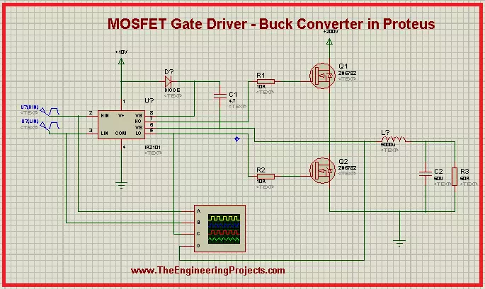
Hey Geeks! Welcome to The Engineering Projects. We hope you are doing great. MOSFET is a predominant component widely used in electronics due to its performance. We are working on the Projects of MOSFET and today's experiment is really interesting. We are working on the MOSFET Gate Driver and we will work on the following concepts:
  1. Introduction to MOSFET Gate Driver.
  2. Circuit of MOSFET Gate Driver.
  3. Working of MOSFET Gate Driver.
  4. Simulation of MOSFET Gate Driver in Proteus.
  5. Applications of MOSFET Gate Driver.
You will find important information about the topic in DID YOU KNOW sections.

Introduction to MOSFET Gate Driver

We all know MOSFET is a type of transistor and is used in a wide range of circuits. It has many interesting features and the characteristics of MOSFET are at the fingertips of electrical and electronic engineers. The circuit of the MOSFET Gate Driver may be new for many students so let's have a look at its definition:
"The MOSFET Gate Driver is a type of DC to DC power amplifier that in the form of on-chip as well as discrete module in which we use MOSFET as the gate driver IC, the low power is taken as input from MOSFET and high power is obtained its gate terminal and vice versa according to need." 

DID YOU KNOW?

The name of the MOSFET Gate Driver is due to its characteristic to have the high current drive gate input of a Transistor. We use the MOSFET because it is a gate driver IC.
MOSFET is used in this circuit because it is commonly used in switching devices where the frequency ranges from hundred of KHz to thousands of KHz. It is mostly used in appliances where we need DC to DC amplification. It is used in computers to low their temperature during their performance. The MOSFET Gate driver is used to change the value of DC according to the circuit of the appliances. There are three types of drivers:
  1. High side drivers.
  2. Low side Driver.
  3. Isolated Drivers.
 

Circuit of MOSFET Gate driver

When we look at the circuit of the MOSFET Gate drive, we found there are some basic as well as some special components in the circuit. In addition to MOSFET, the circuit consists of resistor, capacitor, inductor and IR2101. Let's look at their functions:

MOSFET

  • Metal Oxide Semiconductor Field Effect Transistors have a thin layer of silicon oxide between Gate and channel. It four terminals:  Gate, Drain, Source.

IR2101

It is IC that works very great with MOSFET. We use it in the MOSFET Gate driver to insert the voltage in the Gate terminal of the MOSFET in the form of pulses. We define the IR2101 as:
"It is  seven pins, high power, high voltage, MOSFET and IGBT driver that has independent high and low channel references."
The detail of the pins is given as:
  1. Vcc: This Pin is for Low side and logic fixed supply voltage.
  2. Vs: It is for High side floating supply offset voltage.
  3. Hin: High side gate driver output is taken by this pin.
  4. HO: We get High side gate drive output through this pin.
  5. Lin: Low side gate driver output is taken by this pin.
  6. LO: Low side gate drive output is obtained through it.
  7. COM: we get Low side return from this pin.
Other components are very common to discuss.

Working of MOSFET Gate Driver

The working of the MOSFET Gate Driver start when the power is generated from power terminals.
  1.  The IR2101 starts with the power terminal, the input pulse generators convert this power into the special length as set by the user.
  2. These pulses Enter at the gate terminals of MOSFETs.
  3. Both of these MOSFETs do not turn on at the same time. They work in a loop so that if the high side MOSFET is turned on then the other is off and vice versa.
  4. The MOSFET M1 on the upper side of the circuit is considered at the High side of the driver and the MOSFET M2, on the lower side of the circuit is at the Low side driver.
  5. After some time, when the voltage becomes greater than the threshold voltage of MOSFETs, they start working.
  6. The terminals of  MOSFETs are connected with the capacitor.
  7. The aim of this circuit is to charge the capacitors. Hence when the MOSFET starts working, the charging of the capacitor takes place.
  8. The pulses reach both the MOSFET at a very specific time due to IR2101.
  9. Once the capacitor C2 is fully charged, it starts the discharging power and this discharging power from the inductor as well and at last, it goes to the ground terminal.
  10. In this case, the polarity of the inductor changes and in this way, the energy stored in the capacitor is discharged.
  11. Hence at the end, when we check on the oscilloscope, we get the changed output pulse from the input.

Simulation of MOSFET Gate Driver in Proteus ISIS

Material Required for MOSFET Gate Driver

  1. MOSFET
  2. IR2101
  3. Resistor
  4. Capacitor
  5. Inductor
  6. Ground Terminal
  7. Power Terminal
  8. Pulse Generator
Using all the concepts given above, we'll simulate the circuit in Proteus for a crystal clear concept. Just follow the steps given next:
  • Start your Proteus Software.
  • Make a new Project.
  • Click at "P" button to choose the first five components for the experiment one after the other.
  • Arrange all the components in the working area according to the arrangement given next:
  • Go to Terminal Mode> Ground and add ground terminal with the required components of the circuit.
  • Repeat the above step with the power Terminal.

DID YOU KNOW?

The efficiency of MOSFET Gate driver is more than 90% in many cases.
  • Go to Instrument Mode and take the Oscilloscope from there. Now, arrange it just below the circuit.
  • Connect all the components with the help of connecting wires by carefully following the image given next:
  • Double-tap the components one by one and change the default values according to the table given next:
    Components Values
    R1 10R
    R2 10R
    R3 60R
    L1 500u
    C1 4.7u
    C2 60u
    Pulse 1 Pulse (High) voltage =5v, frequency 1k, Pulse Width 50%
    Pulse 2 Pulse (High) voltage =5v, frequency 1k, Pulse Width 50%
  • Tap the play button at the lower-left corner of the screen to simulate the graph.
  • Set the values of voltage and current through the nob to see a clear output.

Applications of MOSFET Gate Driver

  1. MOSFET Gate driver is used in DC to DC converter.
  2. It is used in the conversion of high voltage to low voltage.
  3. It is mainly used to reduce heat in many circuits.
  4. Due to its functions, it is useful in extending battery life.
So, in the present article, we saw what is MOSFET Gate driver. What important components are used in it, how does its circuit works and how can we simulate its circuit in Proteus. Moreover, we also read some of its applications. We hope you learned well from this article.

Solar Panel Library for Proteus V2.0

Hello friends, I hope you all are well. Today, we are going to share the second version of the Solar Panel Library for Proteus. You should also have a look at the first version of the Solar Panel Library, which we have posted around 2 years back and we were receiving suggestions to reduce its size as there's less space left for other components. That's why we have designed this new Solar Panel Library and have reduced the size of the solar panel. We have also added a new black solar panel component to it. So, this library contains 2 solar Panel modules in it. First, let's have a look at a brief introduction to Solar Panel and then will download the Proteus Library zip file.

What is Solar Panel?

  • Solar Panels are designed using solar cells composed of semiconductor materials(i.e. silicon, phosphorous etc.) and convert solar energy into electrical energy.
  • Solar Panels are used to generate renewable energy and are considered as one of the major sources.
  • Real Solar Panel modules are shown in the below figure:

Solar Panel Library for Proteus V2.0

  • First, we need to download the zip file of Proteus Library by clicking the below button:
Download Proteus Library zip file
  • In this zip file, you need to open the folder named Proteus Library Files.
  • In this folder, you will find 2 Proteus Library files named:
    • SolarPanel2TEP.IDX
    • SolarPanel2TEP.LIB
  • Copy-paste these files in the Library folder of Proteus software.
Note:
  • After adding the files in Proteus software, open it and if you are already working on it, then you need to restart it.
  • In the components section, make a search for solar panel and you will get results as shown in the below figure:
  • In the above figure, the first result is from version 1.0, and the remaining two are added by this new solar library.
  • Let's place these sensors in the Proteus workspace, as shown in the below figure:
  • This Solar Library has thee two solar panels in it, one is blue and the second one is black.
  • Both are of 12V but their voltage level can be changed from the Properties panel.
  • In order to open the Properties panel, double click on the solar panel and you can change the value of Voltage here, as shown in the below figure:
  • Click Ok to close the properties panel.
Now let's design a simple Proteus simulation of Solar Panel in Proteus:

Proteus Simulation of Solar Panel

  • I have changed the voltage level of black solar from the properties panel & simply placed a voltmeter in front of these solar panels, as shown in the below figure:
  • Now let's run the Proteus simulation of solar panel:
  • As you can see in the above figure, the output of black solar is around 16V, while blue solar is giving 12V.
  • That's how you can test it for variable voltage i.e. day time, night time etc.
So, that was all for today. I hope this library will help you guys in your engineering projects. If you have any issues/queries, use the below comment form. Thanks for reading. Have a good day. :)

Vibration Sensor Library for Proteus V2.0

Hello friends, I hope you all are doing great. In today's tutorial, I am going to share a new Vibration Sensor Library for Proteus V2.0. It's the second version of the Vibration Sensor Library for Proteus. In this library, we have four vibration sensors. These vibrations sensors have both digital and analog output pins and can easily be connected with microcontrollers i.e. Arduino, PIC, Atmel etc. Before downloading the Proteus Library zip file, let's first have a look at the brief overview of Vibration Sensor:
Where To Buy?
No.ComponentsDistributorLink To Buy
1Arduino UnoAmazonBuy Now

What is Vibration Sensor?

  • A vibration sensor is a small embedded sensor, which is used to detect vibrations on any surface.
  • These vibration sensors are used for various purposes i.e. fault detection on heavy machinery, placed on doors & windows for security etc.
  • Real vibration sensors are shown in the below figure:

Vibration Sensor Library for Proteus V2.0

  • First of all, download the zip file of Proteus Library for Vibration Sensor, by clicking the below button:
Download Proteus Library Files
  • After downloading the zip file, extract its files and open the folder named "Proteus Library Files".
  • In this folder, you will find 3 Proteus Library Files named:
    • VibrationSensor2TEP.IDX
    • VibrationSensor2TEP.LIB
    • VibrationSensor2TEP.HEX
  • We need to place these files in the Library folder of Proteus software.
Note:
  • After adding these library files, open your Proteus software or restart it, if it's already running.
  • In the components section, make a search for Vibration, and you will get results, as shown in the below figure:
  • In the above search result, the first four modules are from V2.0, while the fifth one is of the first version.
  • Let's place these first four modules in the Proteus workspace, as shown in the below figure:

Adding Hex File to the Sensor

  • Next, we need to add the hex file of the sensor, so double click on the sensor to open its Properties Panel.
  • In the Program File section, browse to the hex file, which we have downloaded above and placed it in the Library folder of Proteus software:
  • After adding the hex file, click the Ok button to close the properties panel.
The vibration sensor is now ready to simulate in Proteus, so let's design a simple circuit to understand its working:

Vibration Sensor Proteus Simulation

  • I have simulated two of these vibration sensors, as shown in the below figure:
  • As you can see, I have placed an LC filter on the analog output of the vibration sensor, its because proteus gives us a peak to peak voltage value and we need t convert it to Vrms.
  • This LC filter is not required in real hardware.
  • Now, let's run the Proteus simulation and if everything's fine, you will get results as shown in the below figure:
  • As the potentiometer value is different on both sensors, that's why we are getting different outputs.
So, that was all for today. I hope this sensor will help engineering students in their projects' simulations. Thanks for reading. Have a good day. Bye !!! :)
Syed Zain Nasir

I am Syed Zain Nasir, the founder of <a href=https://www.TheEngineeringProjects.com/>The Engineering Projects</a> (TEP). I am a programmer since 2009 before that I just search things, make small projects and now I am sharing my knowledge through this platform.I also work as a freelancer and did many projects related to programming and electrical circuitry. <a href=https://plus.google.com/+SyedZainNasir/>My Google Profile+</a>

Share
Published by
Syed Zain Nasir