Interface LCD 16x2 with Raspberry Pi 4

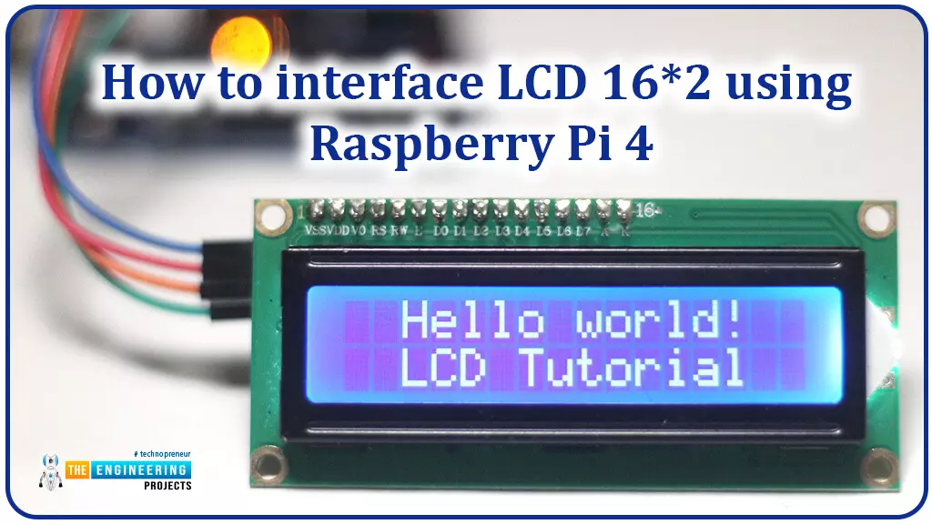
Hello friends, I hope you all are doing great. Today, I am going to share the 6th lecture in the Raspberry Pi 4 Programming series. We're glad you could join us for another lesson in our comprehensive Raspberry Pi programming guide. In today's guide, I'll show you how to interface a 16x2 LCD screen with Raspberry Pi 4.

So, let's get started:

Interface LCD 16x2 with Raspberry Pi 4

Today, we are going to interface a 16x2 LCD screen with Raspberry Pi 4. At first, we will print the "Hello World" text on the LCD, and in the last section, we will implement the scrolling and blinking of text on the LCD.

  • Here's the video tutorial on LCD interfacing with Raspberry Pi 4:


Components Required

We will need the following components for today's project:

    • Raspberry Pi 4.
    • Micro SD Card.
    • 16x2 LCD.
    • Breadboard.
    • Jumper wires.

    LCD 16x2 Display

    • A liquid crystal display, or LCD, is a versatile electronic display module. The 16x2 LCD module is used in electronic gadgets and circuits to display data normally sensor values.
    • LCD 16x2 has 16 columns and 2 rows, which means we can write 32 characters on it.
    • This LCD uses a 5x7 pixel matrix to show each character and 224 distinct characters/symbols can be displayed on the 16x2 programmable alphanumeric dot matrix display.
    • The Command register and Data register are the two command types in this LCD.
    • Simple LCD screens use a controller from the HD44780 family.
    • LCDs have supplanted CRTs (Catalyst Ray Tubes) in the screen manufacturing industry because CRTs are bulkier, heavier, and consume more energy than LCDs. LCD screens are more slender than their CRT counterparts.
    • Since LCDs are based on a light-blocking rather than a light-dissipating technology, they require less electricity than LED panels.
    • LCDs are everywhere, from CD, DVD players and digital watches to computers and televisions.

    LCD 16×2 Pinout

    • LCD 16x2 has 16 pins in total, where 8 pins are used for data transmission, while the remaining 8 pins are used to control LCD.
    • LCD 16x2 Pinout is shown in the below figure:
    • Pin 1 and 2 are power pins and we need to provide GND and +5V to these pins respectively.
    • Pin 3 is Contrast Pin and controls the brightness of LCD, so we normally place a potentiometer at this pin, to get the desired brightness.
    • Pin 4 is the register select pin, used to select the Command Register or Data Register.
    • Pin 5 is the Read/Write Pin, it needs to set LOW if you want to write on the LCD and needs to set HIGH if you want to read from the LCD.
    • Pin 6 is Enable Pin, used to enable the LCD by setting it HIGH.
    • Pins 7-14 are data pins(labeled D0-D7) and are used to get data for the LCD.
    • Pin 15 & 16 are power pins and are used for the backlight of the LCD.
    • Below you'll find a diagram depicting a standard LCD board's pin configuration.

    The header pins of 16x2 monitors are not pre-soldered. Normally a male header pin is soldered to the LCD pin holes.

    Modes of Communication

    We can perform 2 types of communication modes in LCDs, named:

    • 8-Bit Mode.
    • 4-Bit Mode.

    In 8-Bit mode, all 8 data pins are used to send data, while in 4-Bit mode, the last 4 pins(D4-D7) are used for data transmission.

    LCD Registers

    LCDs employ two distinct registers:

    • Data register.
    • Command register.

    You can use the RS pin on LCD to alter the register. If RS is High, we are accessing the data register and if it's Low, we are accessing the command register.

    The LCD's command register keeps track of the user's command. Pre-display data is saved in the data register. In order to manipulate the display, one must first load the instruction register with commands and then load the data registers to display the data. If you're working on a Raspberry Pi project and want to avoid learning low-level commands, you can use the Liquid Crystal Library instead.

    LCD Brightness

    The screen's brightness can be adjusted from Pin 3, normally a potentiometer is placed at Pin 3 to adjust the brightness. You can also use a resistor if you don't have a potentiometer. If a resistor is used, try one between 5k-10k ohms. You should experiment with a few different values to get the optimal resistance.

    Working Principle

    LCD works on the principle of light transmission from one layer to the next via molecules. These units vibrate and align themselves in a way that the polarized sheet gets at an angle of 90 degrees, allowing light to pass through. In other words, these molecules inspect the information on every pixel. Every single pixel uses the light absorption technique to display the digits. It is necessary to adjust the molecular orientation to the incident light angle in order to show the value.

    Circuit Diagram of RPi4 with LCD

    The 16x2 LCD screen can easily be connected to the Raspberry Pi 4. There will be a lot of cables to connect because LCD has 16 pins, but nothing too complicated. Here's the schematic of the pin connections between RPi4 and LCD:

    1. Connect Pin 1, 5(R/W Pin) and 16 of the LCD module to the Ground(GND).
    2. Connect Pin 2 and 15 of the LCD screen to Vcc(+5V).
    3. Connect Pin 3 to the Potentiometer's middle Pin, while the remaining two pins of the potentiometer need to connect to Vcc and GND.
    4. Connect Pin 4 of the LCD screen to the GPIO25(Pin 22) of Raspberry Pi 4.
    5. Connect Pin 6 of the LCD module to the GPIO24(Pin 18) of Raspberry Pi 4.
    6. Pin 11(D4) is connected to GPIO23(Pin 16).
    7. Pin 12(D5) is connected to  GPIO17(Pin 11).
    8. Pin 13(D6) is connected to GPIO18(Pin 12).
    9. Pin 14(D7) is connected to GPIO22(Pin 15).

    Having done so, the screen should power up and establish a connection with the RPi.

    Python Code for Rpi4 with LCD 16x2

    The newest Raspbian release has all the necessary packages loaded out of the box to allow for GPIO communication. But we need to install the Liquid Crystal Library to work on the LCD. Let's do that:

    Python Library for LCD

    • We will install the Adafruit LCD library.
    • It was made with Adafruit LCD boards in mind, but it can also be used with boards from other manufacturers. If the controller on your display board is an HD44780, you shouldn't have any problems.
    • First of all, use the below command to clone the necessary git directory onto the Raspberry Pi:

    git clone https://github.com/pimylifeup/Adafruit_Python_CharLCD.git

    • After that, navigate to the directory where the clone was created and double-click the setup file or use the below commands to install the library:

    cd ./Adafruit_Python_CharLCD

    sudo python setup.py install

    After the installation, you can use the Adafruit library from any Python program on the Pi. Just paste this line into the beginning of your Python file to make use of the library.

    import Adafruit_CharLCD as LCD

    Interacting with the LCD Screen

    The Adafruit LCD library makes it simple to display data from Raspberry Pi to LCD screen. The library package also has several working examples of utilizing the LCD. Before running any of these examples, make sure the pin parameters at the top of the program reflect your setup. My Circuit should yield the following results.

    lcd_rs        = 25 

    lcd_en        = 24

    lcd_d4        = 23

    lcd_d5        = 17

    lcd_d6        = 18

    lcd_d7        = 22

    lcd_backlight = 4

    lcd_columns = 16

    lcd_rows = 2

    • Enter the below commands to access one of the sample files:

    cd ~/Adafruit_Python_CharLCD/examples/

    sudo nano char_lcd.py

    Change the values in this section to match the ones described above for the pin configuration. To save the code, hit CTRL+X+Y on your keyboard. To execute this code, open a terminal and type Python followed by the name of the file (including the extension).

    python char_lcd.py

    Functions and Python Code

    In this session, I'll go over the fundamental Python methods for interacting with the screen. To initialize the pins, it is necessary to invoke the following class. Before calling the class, make sure all the parameters have been defined.

    lcd = LCD.Adafruit_CharLCD(lcd_rs, lcd_en, lcd_d4, lcd_d5, lcd_d6, lcd_d7, lcd_columns, lcd_rows, lcd_backlight)

    After that, you can adjust the screen to your liking. In this short guide, I'll give you a taste of what you can do with the Adafruit library.

    • By calling "home()", you can return the cursor to its original position in the first column of the first line.
    • The command "clear()", wipes the LCD clean, making it completely blank.
    • Set the current cursor position using "set cursor(col, row)". The column, as well as row numbers, are supplied as arguments, which determine the location i.e. "set cursor (1,4)".
    • The display can be turned on or off with the enabled "display(enable)" function.
    • The cursor can be displayed or hidden with the "cursor(show)" function. If you wish to see the pointer, set this to true.
    • The cursor blinks on and off with the "blink(blink)" command. Setting this to true will cause the cursor to blink.
    • The move left() and move right() functions, shift the pointer to the left and right by one cell.
    • The cursor direction can be changed using set right to the left() or set left to right().
    • If "autoscroll" is true, the text will right align from the cursor. The text will be aligned to the left if this option is false.
    • Message (text) - Outputs the given text on the screen. Include new lines (n) in your message if you'd like.

    The Ardafruit CharLCD.py file in the Adafruit CharLCD folder of the Adafruit Python CharLCD folder will list all the accessible methods.

    sudo nano ~/Adafruit_Python_CharLCD/Adafruit_CharLCD/Ardafruit_CharLCD.py

    My simple script for displaying user-entered text is included below.

    #!/usr/bin/python

    # Example using a character LCD connected to a Raspberry Pi

    import time

    import Adafruit_CharLCD as LCD

    # Raspberry Pi pin setup

    lcd_rs = 25

    lcd_en = 24

    lcd_d4 = 23

    lcd_d5 = 17

    lcd_d6 = 18

    lcd_d7 = 22

    lcd_backlight = 2

    # Define LCD column and row size for 16x2 LCD.

    lcd_columns = 16

    lcd_rows = 2

    lcd = LCD.Adafruit_CharLCD(lcd_rs, lcd_en, lcd_d4, lcd_d5, lcd_d6, lcd_d7, lcd_columns, lcd_rows, lcd_backlight)

    lcd.message('Hello\nworld!')

    # Wait 5 seconds

    time.sleep(5.0)

    LCD.clear()

    text = raw_input("Type your name in the terminal ")

    LCD.message(text)

    # Wait 5 seconds

    time.sleep(5.0)

    LCD.clear()

    lcd.message('Goodbye\nWorld!')

    time.sleep(5.0)

    LCD.clear()

    If everything's fine, you will get something printed on your screen, as shown in the below figure:

    If your Python script isn't producing any output on the screen, it's probably due to incorrectly configured pins.

    Conclusion

    This guide walked you through connecting the Pi 4 to a 16x2 LCD. You can accomplish so much more with this sleek screen. You may set up a script to run at boot time and show useful information like the IP address, time, temperature, and more.

    You can also incorporate a wide variety of interesting sensors with this screen. A temperature sensor like the DS18B20 would be ideally suited for use with the screen. Refresh the screen every few seconds to reflect the current temperature.

    Please let me know how successful you were in putting up a Pi 4 with LCD 16x2 display with the help of this tutorial. In the next tutorial, we will interface Keypad 4x4 with Raspberry Pi 4. Till then, take care. Have fun !!!

    Interface RFID Module RC522 with Raspberry Pi 4

    We're glad you could join us for another lesson in our comprehensive Raspberry Pi programming guide. I will show you how to install and connect the RFID card chip to your Raspberry Pi through step-by-step instructions.

    Modern security systems would only be complete using radio frequency (RFID) devices. To control who can enter a facility or which rooms they can access, RFID chips and card readers are employed. The RFID card's unique identification number can be read wirelessly with a wall-mounted RFID reader. A door will only unlock and allow entry if the RFID card's unique identification number matches a list of approved cards.

    It's fun to tinker with this circuit, and it may be used in many other applications, from opening locks to taking attendance. The MFRC522 microcontroller underpins the RFID RC522, a cheap RFID (Radio-frequency identification) reader/writer. The RFID tags can connect with this microcontroller using an electromagnetic field it generates at 13.56MHz and sends to them via the SPI protocol. If you want to use your RFID RC522 with tags, you must ensure that they are 13.56MHz compatible. We'll walk you through the wiring of the RC522 and the creation of Python programs to communicate with the chip, allowing you to read and write RFID tags. Adding a 16x2 LCD to the Raspberry Pi is a simple extension of this tutorial, and it can be helpful if you need to show the user some information or provide a visual prompt.

    Where To Buy?
    No.ComponentsDistributorLink To Buy
    1BreadboardAmazonBuy Now
    2Jumper WiresAmazonBuy Now
    3Raspberry Pi 4AmazonBuy Now

    Components

    • Raspberry Pi

    • Micro SD Card

    • Power Supply

    • RC522 RFID Reader

    • Breadboard

    • Breadboard Wire

    What is an RFID RC522

    An RFID reader reads the tag's data when a Rfid card is attached to a specific object. An RFID tag communicates with a reader via radio waves.

    In theory, RFID is comparable to bar codes because it uses radio frequency identification. While a reader's line of sight to the RFID tag is preferable, it is not required to be directly scanned by the reader. You can only read an RFID tag up to three feet away from the reader. The RFID tech quickly scans many objects, making it possible to identify a specific product rapidly and effortlessly, even if it is sandwiched between several other things.

    Explained: the functioning of rfid readers and writers

    Major components of Cards and tags include an integrated circuit (IC) that stores the unique identification value and a copper that acts as the antenna.

    Inside the Rfid reader is another copper wire coil. This coil produces a magnetic field when current flows through it. Magnetic flux creates a current inside the wire coil when the card is brought close to the reader. This current can power the card's internal integrated circuit. The reader then takes in the card's serial number. A card reader will send the card's serial number to a central processing unit (CPU) like a Raspberry Pi for further processing.

    Assembling the RFID RC522

    When you buy an RFID RC522 Reader, you may discover that 90% of them do not have the header pins pre-installed. Due to a lack of pins, you'll have to solder them yourself; however, this is a relatively easy task, even for amateurs. Assuming the header pins that came with your RC522 are too large, you may snap them in half to reduce them to a single column of eight.

    Start by inserting the header pins into the RC522 from the top. The circuit may be easily placed on top of the connector pins by inserting the large side of the pins onto a breadboard. The breadboard's secure holding of the pins will make soldering them to the RFID circuit much simpler.

    Solder each pin individually by carefully heating your soldering iron and applying it to the pins. Remember that heating the junction slightly before to solder application increases the solder's adhesion and decreases the likelihood of generating a cold joint. When using solder, we advise you to be conservative. When you've finished soldering the header pins onto your RFID circuit, you'll be ready to move on with the guide.

    Wiring the RFID RC522

    There are eight different connectors on the RFID RC522. Except for the IRQ, we need to connect all these to the GPIO pins on our Raspberry Pi.

    This guide shows how to connect an RFID RC522 to a Breadboard and then to the Raspberry Pi's GPIO Pins, although you could also wire the components straight to the Pi.

    Simply connecting 7 of the Raspberry Pi's GPIO pins to the RFID RC522 reader is all needed to get it up and to run. Refer to the GPIO pin locations detailed in our tutorial and the table below when deciding how to wire your RC522.

    • SDA connects to Pin 24.

    • SCK connects to Pin 23.

    • MOSI connects to Pin 19.

    • MISO connects to Pin 21.

    • GND connects to Pin 6.

    • RST connects to Pin 22.

    • 3.3v connects to Pin 1.

    Setting up Raspbian for the RFID RC522

    We need to adjust the Raspberry Pi's settings before we can use the RFID RC522. Inconveniently, our RFID reader circuit relies on the Raspberry Pi's SPI (Serial Peripheral Interface), which is disabled by default. Worry not, though, as it is easy to restore this interface; follow our instructions below to set up your RPi and Raspbian to use the SPI port. Launch the raspi-config utility by opening a terminal and typing the following command.

    sudo raspi-config

    A menu of choices will appear when you use this tool. You may read up on all of these options in the raspi-config documentation. Choose "5 Interfacing Options" using the arrow keys. Select this choice, and then hit the Enter key. Once "P4 SPI" is selected in the next screen, press Enter once more to confirm your selection. To continue, use the arrow keys to choose "Yes" and then press Enter when prompted to confirm that you want to activate the SPI Interface. For the raspi-config utility to finish enabling SPI, you'll have to be patient for a while.

    The raspi-config tool's success in enabling the SPI interface will be shown by the display of the message "The SPI interface is enabled." Activating the SPI Interface requires a full reboot of the Raspberry Pi. Press Enter, and then ESC, to return to the terminal. If you want to restart the RPi, enter the following Unix instruction into the terminal.

    sudo reboot

    It is time to verify that Raspberry Pi has been activated now that it has rebooted. Checking if spi bcm2835 is available is as simple as running the following command.

    lsmod | grep spi

    If you get spi bcm2835, you're good to go with the rest of the tutorial. If you tried the preceding command and it didn't work, try the following three things. If the SPI component is not enabled, we can manually modify the boot config file by issuing the following code to our RPi.

    sudo nano /boot/config.txt

    You can use CTRL + W to search the configuration file for "dtparam=spi=on" If you think you have discovered it, look if it has a number in front of it. If there is, delete it because it disables the code. If you cannot find the line, add "dtparam=spi=on" to the very end of the file. To commit your modifications, use CTRL + X, followed by Y and Enter. You can double-check that the module has been activated by restarting your Raspberry Pi, as in Step 5.

    Getting Python ready for the RFID RC522

    After connecting our RFID circuit to the RPi, we can turn it on and start writing Python scripts to communicate with the chip. You'll learn how to read and write information to RFID chips by composing scripts like the ones we'll provide. These will serve as the foundation for future RFID RC522 tutorials and provide you with a fundamental understanding of how data is handled. The Raspberry Pi must be brought up to date with the most recent software versions before we can begin programming. Get the latest version of Raspbian for your Pi by running these two commands.

    sudo apt update

    sudo apt upgrade

    Installing the python3-dev, python-pip, and git packages is the last thing to do before moving forward. To get your RFID reader set up with this guide, type the following command into your Raspberry Pi's terminal.

    sudo apt install python3-dev python3-pip

    Now that we have python "pip" installed on our Raspberry Pi, we can install the spidev Python library. An integral part of this guide, the spidev library allows the RPi to communicate with the RFID via the SPI. Run the following command to get spidev set up on your Raspberry Pi via pip. It's important to remember that we're using sudo to guarantee that the package gets installed for everyone's usage, not just the logged-in user.

    sudo pip3 install spidev

    After getting the spidev library up and running on our Raspberry Pi, we'll move on to setting up the MFRC522 library with pip. Two files, in particular, are used by us, both of which are part of the MFRC522 library:

    This library, MFRC522.py, implements the RC522 interface for communicating with RFIDs via Raspberry Pi's SPI port.

    Simplifying the MFRC522.py file so that you only need to work with a small subset of its many functions, SimpleMFRC522.py is a significant time saver.

    Enter this command into your terminal to have pip setup the MFRC522 library on your Pi 4:

    sudo pip3 install mfrc522

    Now that the library has been transferred to the Pi, we can start writing code for the RFID RC522. First, we'll explore how to use the RC522 to program your RFID cards. Move on to the following part, where we will write our first Python code.

    Writing with the RFID RC522

    In this first Python script, we'll go over the steps needed to send information from the RC522 to RFID tags. This is made more accessible by the SimpleMFRC522 script, but we'll still break down the code's individual components for you. To begin, let's create a directory to hold the scripts we'll be using. Create the "pi-RFID" folder by using the following command.

    mkdir ~/pi-rfid

    To get started, navigate to the folder you just cloned and create the Write.py script in Python.

    cd ~/pi-RFID

    sudo nano Write.py

    Add the following blocks of code to this file. This code prompts you for some text, which it then uses to update the RFID Tag.

    #!/usr/bin/env python

    import RPi.GPIO as GPIO

    from mfrc522 import SimpleMFRC522

    The very first line of the code snippet instructs the terminal to use Python rather than another scripting language like Bash to parse and run the file. To guarantee that the GPIO Pins are reset when the script terminates, we must first import the RPi.GPIO package contains all the necessary functions for communicating with the GPIO Pins. The second import is our SimpleMFRC522 library, which will be used to communicate with the RFID RC522. Compared to the standard MFRC522 library, it dramatically simplifies working with the chip.

    reader = SimpleMFRC522()

    In this line, we make a new instance of the SimpleMFRC522 object, use its setup function, and save the result in our readers variable.

    try:

            text = input('New data:')

            print("Now place your tag to write")

            reader.write(text)

            print("Written")

    We enclose the following section of code with a try statement to ensure that any unforeseen problems are handled, and the code is cleaned up correctly. Python is whitespace sensitive; it uses tabs to distinguish between code sections, so keep them after trying. In this case, the second line reads a command-line input and stores it in a text variable using Python 3's input function.

    The third line makes advantage of print() to prompt the user to set the RFID tag onto the reader. After that, on line 4, we utilize our scanner object to instruct the RFID Circuit to write the text field's contents to a certain sector of the RFID tag. On line 5, after successfully writing to the RFID tag, we call print() once more to inform the user.

    finally:

            GPIO.cleanup()

    The script will terminate in the last two lines of code. The finally statement always follows the try statement. Thus the GPIO.cleanup() method is called after each iteration of the try block. These lines are essential because improper cleanup can disrupt the functionality of other programs. Upon completion, your script should be like the example given below.

    The file can be saved by pressing CTRL Plus X, Y, then ENTER once you've double-checked the code and are convinced it's correct. Now that the script is written, we need to put it through some testing. Get an RFID tag ready before running the script for testing. When you're ready, open the terminal on your Raspberry Pi and enter the following command.

    sudo python3 Write.py

    In this situation, we're just going to type in "any word" because it's easy to remember and short. Press the Enter key when you have finished writing and are ready to send. After that, your RFID Tag can be placed directly above your RFID circuit. It will immediately update the tag with fresh information when it does. You'd see the word "Written" on the command prompt if it worked. Now that you have your Write.py script completed, we can move on to explaining how to read information from the RFID RC522.

    Reading with the RFID RC522

    We have successfully programmed our RC522 to print to RFID tags and can now move on to writing a script to retrieve the data from the tags. First, we'll make sure we're in the correct location by switching directories, and then we'll use nano to start drafting the Read.py script.

    cd ~/pi-rfid

    sudo nano Read.py

    Incorporate the following code into this document. When an RFID tag is placed in the RFID reader, the script will wait until the tag's data has been read before displaying the results.

    This file's first line of code instructs the operating system on how to proceed when the user clicks the "Run" button. If you don't specify that it's a Python file, it'll try to run it like any other script. An initial RPi.GPIO import is made. Importing this library ensures that the Raspberry Pi's GPIO pins are cleaned up after script termination, as it contains all the necessary functions. SimpleMFRC522 is the second import. With the assistance functions included in this script, reading and writing to an RFID RC522 is a breeze, whereas, with them, the scripts would quickly grow to be manageable.

    This line is crucial because it invokes SimpleMFRC522's creation method, which returns an object that is subsequently stored in our reader variable.

    try:

            id, text = reader.read()

            print(id)

            print(text)

    The following code section will be encapsulated in a try block to allow us to handle any unforeseen errors gracefully. Because Python is sensitive to whitespace, you must use the 'tabs' as displayed following try:

    In this scenario, the second line of this code block initiates a call on our scanner object, instructing the circuits to begin scanning any Rfid card that is positioned on top of the reader. On the third and forth lines, we use print() to display the data we gleaned from the RFID Chip; this includes the tag's unique identifier and any text it may consist of.

    finally:

            GPIO.cleanup()

    The script ends with the last two lines of code. No of what happens inside the try block, the final statement is always executed afterward. No matter what, the GPIO.cleanup() code will be executed thanks to this try statement. It's vitally important, as not doing so can disrupt the proper operation of other scripts that rely on the GPIO. Your completed Read.py script for the RFID RC522 should resemble the example below.

    When you've double-checked your code and are satisfied with it, press Ctrl + X, then Y, and finally ENTER to save the file. The time has come to put our completed Read.py script to the test. Get ready to test the script by picking up any of the RFID tags. If you're all set, enter this command into the terminal on your Raspberry Pi.

    sudo python3 Read.py

    Now that the script is active, you can set your RFID Tag atop your RFID circuit. When the RFID tag is placed on top, the Python program will immediately begin reading the information from the tag and display the results on the screen. What a finished product might look like is shown below as an illustration.

    To test whether your Raspberry Pi is properly connected on the RFID RC522 Circuit, run the Read.py script and see if it returns any data that matches the text you wrote to the card in the Write.py script.

    Conclusion

    Connecting an RC522 RFID module to a Pi 4 makes reading MIFARE chips and cards is now possible. This might be very useful in security systems and other applications where identifying an item or person is required without the user having to physically interact with the device by pressing buttons, switching, or activating any sensors. Eventually, you should be able to use this to decipher the UID encoded on your MIFARE tags. You should know that these cards can be duplicated and assigned a new unique identifier (UID) if you plan on employing this technique in a security system. To ensure the safety of your system, you must ensure that no one learns your UID or gains remote access to your devices. The contactless tags are convenient because they can be attached to a keychain, and the cards are convenient because they can be carried in a wallet. Both things can be concealed inside others to give them a hidden identifier that the Pi can access. With the help of our Pi 4-powered RFID attendance systems guide, you can learn how to set up your RFID Reader/Writer for use in checking attendance. Our exploration of the RFID chip and the scripts above will continue in subsequent guides. A door security system is one of the fantastic DIY Pi ideas we'll look into. The next lesson will teach you how to connect a 16x2 LCD screen to a Raspberry Pi 4.

    4 Reasons Your Engineering Firm Needs Fleet Maintenance Software

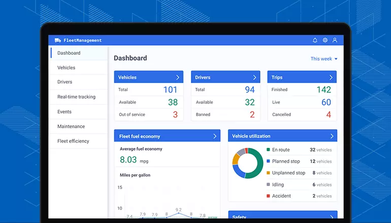
    No matter your company's industry, you need fleet maintenance software. It’s something you need if your engineering firm has a fleet of vehicles. Failing to get the necessary tools is a bit like driving blind -- not the best course of action by any stretch of the imagination.

    If you’re not sold on the benefits of investing in fleet maintenance software, keep reading to learn more about four reasons you need it.

    1. Preventative Maintenance

    Fleet maintenance software will help your engineering firm with preventative maintenance. The software will make it easy to schedule maintenance so that your fleet of cars stays in good shape. 

    One of the worst things you can do is delay or ignore preventative maintenance. That will ultimately cost you in terms of downtime stemming from repairs. Preventative maintenance won’t eliminate the possibility of repairs, but it will reduce the odds of breakdowns . And breakdowns can become expensive if you also find yourself unable to use the company vehicles for business. Unplanned downtime is a no-no.

    2. Lower Repair Costs

    When your business invests in fleet maintenance software, you’ll also enjoy lower vehicle repair costs. Putting off maintenance means that small problems can morph into major issues that cost an arm and a leg to fix. So, it’s more cost-effective to invest in preventive maintenance than to postpone doing so and having to spend many times more to fund major repairs. 

    When considering the importance of your fleet, you can appreciate the need to ensure the vehicles are available and in good repair whenever they’re needed. You can increase uptime and reduce downtime by tackling issues as soon as they’re discovered so that they don’t worsen.

    3. Better Fuel Efficiency

    When you get one of the best fleet maintenance software applications, you’ll also benefit from better fuel efficiency. Proper maintenance and repairs will ensure your fleet of vehicles operates more efficiently, resulting in better fuel efficiency. You can also optimize routes so that drivers don’t take longer routes than necessary. And by keeping track of driver behavior, like speeding or hard braking, you can notify drivers of necessary changes. You can save a lot on fuel just by getting drivers to operate the fleet vehicles more responsibly.

    4. Fewer Headaches

    Who has time to worry about their fleet of vehicles? You have other things to worry about such as operating your engineering firm. When you’re taking good care of your cars, you won’t be left worrying about them. Instead of having to make frequent arrangements to have your inoperational cars towed to automotive facilities for repairs, you’ll be able to use them for business purposes. They’ll spend more time on the road and less time out of commission.

    That means you’ll have fewer headaches with your fleet of vehicles. Using a fleet maintenance software solution, you’ll be able to stay on top of things. And if things don’t get out of control, you’re less likely to have headaches over something going horribly wrong.

    If your engineering firm has a fleet of vehicles, it’s essential to consider the benefits of fleet maintenance software. Protecting your assets is a must if you want them to remain in good repair over the long haul. Getting a fleet of vehicles requires a tangible investment. If you want to protect your investment, then investing in fleet maintenance software is a good idea.

    Before settling on a platform, you’ll want to do research to find something that meets your company’s needs. When you find the right software, you’ll see up close and personal what the benefits of fleet maintenance software are all about.

    Syed Zain Nasir

    I am Syed Zain Nasir, the founder of <a href=https://www.TheEngineeringProjects.com/>The Engineering Projects</a> (TEP). I am a programmer since 2009 before that I just search things, make small projects and now I am sharing my knowledge through this platform.I also work as a freelancer and did many projects related to programming and electrical circuitry. <a href=https://plus.google.com/+SyedZainNasir/>My Google Profile+</a>

    Share
    Published by
    Syed Zain Nasir