Introduction to NodeMCU V3
Hi Friends! Welcome you onboard. I am back to give you a daily dose of useful information. Today, I'll unlock the detailed Introduction to NodeMCU V3. It is an open-source firmware and development kit that plays a vital role in designing your own IoT product using a few Lua script lines.
The module is mainly based on
ESP8266 that is a low-cost Wi-Fi microchip incorporating both a full TCP/IP stack and microcontroller capability. It is introduced by manufacturer Espressif Systems - A manufacturer based in Shanghai, China.
Arduino Modules and Microcontrollers have always been a great choice to incorporate automation into the relevant project. But these modules come with a little drawback as they don't feature a built-in WiFi capability, subsequently, we need to add external WiFi protocol into these devices to make them compatible with the internet channel.
This is where NodeMCU V3 comes handy that incorporates a built-in WiFi support, giving an easy pathway to design IoT applications as per your technical requirements.
In this post, I'll try to cover brief details related to this WiFi Development Kit, its main features, pinout and everything you need to know about this module. Let's get started.
Introduction to NodeMCU V3
NodeMCU V3 is an open-source firmware and development kit that plays a vital role in designing your own IoT product using a few Lua script lines.
Multiple GPIO pins on the board allow you to connect the board with other peripherals and are capable of generating PWM, I2C, SPI, and UART serial communications.
- The interface of the module is mainly divided into two parts including both Firmware and Hardware where former runs on the ESP8266 Wi-Fi SoC and later is based on the ESP-12 module.
The firmware is based on Lua - A scripting language that is easy to learn, giving a simple programming environment layered with a fast scripting language that connects you with a well-known developer community.
And open source firmware gives you the flexibility to edit, modify and rebuilt the existing module and keep changing the entire interface until you succeed in optimizing the module as per your requirements.
- USB to UART converter is added on the module that helps in converting USB data to UART data which mainly understands the language of serial communication.
Instead of the regular USB port, MicroUSB port is included in the module that connects it with the computer for dual purposes: programming and powering up the board.
- The board incorporates status LED that blinks and turns off immediately, giving you the current status of the module if it is running properly when connected with the computer.
The ability of module to establish a flawless WiFi connection between two channels makes it an ideal choice for incorporating it with other embedded devices like Raspberry Pi.
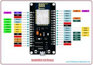
NodeMCU V3 Pinout
NodeMCU V3 comes with a number of GPIO Pins. Following figure shows the Pinout of the board.
- There is a candid difference between Vin and VU where former is the regulated voltage that may stand somewhere between 7 to 12 V while later is the power voltage for USB that must be kept around 5 V.
NodeMCU V3 Datasheet
- You can download NodeMCU V3 datasheet by clicking the below button:
Download NodeMCU V3 Datasheet
NodeMCU V3 Features
- Open-source
- Arduino-like hardware
- Status LED
- MicroUSB port
- Reset/Flash buttons
- Interactive and Programmable
- Low cost
- ESP8266 with inbuilt wifi
- USB to UART converter
- GPIO pins
As mentioned above, a cable supporting micro USB port is used to connect the board. As you connect the board with a computer, LED will flash. You may need some drivers to be installed on your computer if it fails to detect the NodeMCU board. You can download the driver from
this page.
Note: We use
Arduino IDE software for programming this module. It is important to note that the pin configuration appearing on the board is different from the configuration we use to program the board on the software i.e. when we write code for targeting pin 16 on the Arduino IDE, it will actually help is laying out the communication with the D0 pin on the module.
Following figure the shows the pin configuration to use in Arduino IDE.
How to Power NodeMCU V3?
You can see from the pinout image above, there are five ground pins and three 3V3 pins on the board. The board can be powered up using the following three ways.
USB Power. It proves to an ideal choice for loading programs unless the project you aim to design requires separate interface i.e. disconnected from the computer.
Provide 3.3V. This is another great option to power up the module. If you have your own off-board regulator, you can generate an instant power source for your development kit.
Power Vin. This is a voltage regulator that comes with the ability to support up to 800 mA. It can handle somewhere between 7 to 12 V. You cannot power the devices operating at 3.3 V, as this regulator unable to generate as low as 3.3V.
NodeMCU V3 Projects and Applications
NodeMCU V3 is mainly used in the WiFi Applications which most of the other embedded modules fail to process unless incorporated with some external WiFi protocol. Following are some major applications used for NodeMCU V3.
- Internet Smoked Alarm
- VR Tracker
- Octopod
- Serial Port Monitor
- ESP Lamp
- Incubator Controller
- IoT home automation
- Security Alarms
That's all for now. I hope I have given you something valuable related to this module. If you have any question, you can approach me in the comment section below. I'd love to help you the best way I can. You are most welcome to keep us updated with your valuable feedback so we keep producing quality content as per your needs and requirements. Thanks for reading the article.
Introduction to Arduino Leonardo
Hi Guys! Hope you are getting along with life pretty well. I always strive to keep you updated with most valuable information related to engineering and technology. Today, I'll discuss the detailed
Introduction to Arduino Leonardo. It is a microcontroller board based on the ATmega32U4 and comes with 23 digital input/output pins. It is developed by Arduino.cc, aiming to provide easy to use interface with the ability to perform a number of functions on a single chip.
It incorporates everything required to drive the automation in the relevant project. Simply connect this device with the USB cable or power it up using DC adapter and start playing with it
In this post, I'll try to cover each and everything related to Arduino Leonardo, so you don't need to wrestle your mind browsing the whole internet and find all the information in one place. Let's dive right in and get down to the nitty-gritty of this tiny module.
Introduction to Arduino Leonardo
- Arduino Leonardo is a microcontroller board developed by Arduino.cc. It is based on the ATmega32U4 and comes with 23 digital input/output pins that are enough to connect with external devices and turn your innovation into reality.
- The Microcontroller on the board incorporates a built-in USB communication, setting you free from the use of a secondary processor. The USB communication helps Leonardo disguise the mouse or keyboard when it is connected to a computer.
- The module supports the crystal oscillator with the frequency up to 16 MHz that is enough to generate clock pulses with decent pace required for the synchronization of all the internal operations.
In-circuit programming header is added in the device that gives you the flexibility to tweak the already written code after its installation in the relevant project.
- This board supports common communication protocol like UART, SPI, and I2C. The UART is a serial communication protocol mainly used for transferring and receiving serial data using two pins called TX and RX.
While I2C is a two-wire interface that involves two main lines known as SDA and SCL where former is s serial data line that carries the data and later is serial clock line that is used to synchronize all data transfers over the I2C bus.
- Serial Peripheral Interface (SPI) is a third communication protocol added on the board that is commonly used to send data between microcontrollers and small peripherals such as sensors, shift registers, and SD cards using separate clock and data lines, layered with a select line to pick the device for communication.
1. Arduino Leonardo Features
If you aim to work on your desired project, you must know the common features this device holds in order to avoid any hassle in future, getting you a clear idea if the ratings of the device are quite in line and stand fit for your project. Following table shows the main features of the Arduino Leonardo.
Microcontroller |
ATmega32U4 |
CPU |
8-Bit |
Digital I/O Pins |
23 |
PWM Output |
7 |
Analog Input |
12 |
Flash Memory (Program Memory) |
32 KB (Out of which 4 KB is used by bootloader) |
SRAM |
2.5 KB |
EEPROM |
1 KB |
Input Voltage |
7-12 V |
Operating Voltage |
5 V |
Oscillator |
up to 16 MHz |
Software Used |
Arduino Software (IDE) |
Reset Button |
Yes |
ICSP Header |
Yes |
USB Port |
1 |
UART (Serial Communication) |
Yes |
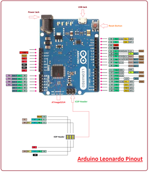
2. Arduino Leonardo Pinout
Following figure shows the pinout of Arduino Leonardo.
- USB jack, Power Jack and Reset button are quite in line with each other and are surfaced on one side of the board. Nonetheless, all components and pins on the board are designed in a regular pattern, giving a compact and symmetrical interface.
3. Arduino Leonardo Pin Description
You have got a clear idea about some of the basic functions of this Arduino Module. In this section, we will break down pinout of the board with different images and describe them in terms of pin description of the board. Let's get started.
Analog Pins
There are 12 analog pins added on the board. As per the nature of these pins, they can utilize any number of values, unlike digital signals that are designed to deal with only two values: HIGH and LOW. The following figure shows the placement of these analog pins on the board.
PWM Output
There are seven PWM pins available on the board. If you place the board with power jack pointing upward, these pins appear on the right side of the board. PWM is a process for getting analog results with digital means. You can see these pins in the figure below.
Communication Protocols
Three communication protocols including SPI, UART and I2C are incorporated on the board. You can see them on the figure below. It is important to note that SPI communication is not available on the digital I/O pins like other boards instead, it houses in the ICSP header as shown in the figure below.
Power Source
Difference power sources are available for a variety of purpose. Mainly, the board operates at 5V while 3.3V is the operating voltage of each pin. The Vin is the input voltage that ranges between +7 to +12 V. This voltage comes from the external power source. There are two ground pins on the board. The AREF is an Analogue reference voltage, mainly used for analog pins.
The IOREF is useful for powering and developing a compatibility between this board and Arduino Shields. As the shield is connected with this pin, it (shield) wears the I/O voltage provided by the Board. The Shield using IOREF pin will be compatible with both 3V3 and 5V.
You can see the power source in the figure below.
ICSP Header
ICPS stands for In-Circuit Serial Programming – A feature used for programming Arduino with another Arduino. ICSP header is added that helps in connecting the board with a computer for uploading a sketch in case USB port is not available.
4. Programming
- Arduino.cc has introduced its own official software, called Arduino IDE, for programming the Arduino module. This software supports common operating systems like Windows, Linux or MAC. Before you download this software, make sure the required software version is compatible with your system i.e. if you aim to download App version, you must have Windows 10 installed in your system as app version is not compatible with Windows 7 or 8.1.
You are ready to use the software as you install it. Some simple LED programs are already available on the software, giving you the flexibility to start working on the board in due course.
- No external burner is required to burn the code inside the module as it comes with a built-in bootloader. Having said that, if you intend to insert a new controller on the module, you need to install the bootloader again using IDE software.
The Serial Monitor is added in Arduino Software, that helps you see the code working in real time as you verify and upload the code.
- Arduino IDE comes with a compilation option that allows you to see the code compilation on the bottom of the screen as you upload the code. It generates hex file of the code which then is transferred into the board.
5. Difference between Arduino Leonardo and Arduino Uno
There is a slight difference between these two boards in terms of controller used, number of digital pins, PWM pins, and the pins reserved for SPI communication.
- Arduino Uno incorporates ATmega328 while Arduino Leonardo comes with ATmega32U4.
Similarly, Uno has 20 digital I/O pins, out of them 6 are analog input pins and Leo has 23 digital I/O pins, out of which 12 are analog input pins.
- There are 7 PWM output pins available on the Leonardo and 6 are added on the Uno board.
Uno comes with SPI protocol on the digital I/O pins while Leonardo contains SPI communication on the ICSP header pins.
6. Arduino Leonardo Projects and Applications
You can not write off the importance of Arduino Modules if you are working on a project that comes with a remote connection with automation. Arduino Leonardo comes with a wide range of applications and incorporates a number of peripherals, setting you free from the hassle of spending too much for buying external components.
Following are some major applications Arduino can be used for:
- Industrial Automation
- Health and Security Systems
- Creating wireless keyboard
- Automatic Pill Dispenser
- Embedded Systems
- Student Projects
- USB Trackpad
- Water Level Meter
That’s all for today. I hope you have got a lot of information regarding Arduino Leonardo. However, if you are unsure or have any question you can approach me in the comment section below. I’d love to help you the best way I can. You are most welcome to keep us updated with your valuable feedback and suggestions, they help us provide you quality work that resonates with your needs and requirements. Thanks for reading the article.