Hi Guys! Happy to see you around. I welcome you on board. In this post today, I’ll detail the future projects that could be possible with software development.
Software development in 2020 is taking over many industries and innovating on so many levels. We have already come so far with the inventions and ideas in today’s age, but there is certainly more to come. We are always on the lookout as humans for the next big thing that will impact lives in a positive way.
Some of the examples are not life-altering by any means, but they are certainly winning for the software development industry. The examples are not currently in place, but I am sure that some of them are being perfected as you read this and might become a reality in the near future ...
Hi Friends! Hope you’re well today. I welcome you on board. In this post today, I’ll detail how apps are saving lives in the wilderness.
Whenever disaster strikes in the wilderness, be it from fires, storms, or other natural disasters, it can be a daunting task for people and animals to get the help they need to get out of potentially life-threatening circumstances. Animals, particularly endangered species, get caught in all kinds of situations that require attention, but obviously, they can’t just pick up the phone and call for help, and for people, they might not have the means to fare much better if their phones are out of service or they get injured and can't move.
When it comes to wildlife rescue operations and conservation, location-based ...
Hi Friends! Hope you’re well today. I welcome you on board. In this post today, I’ll walk you through why cybersecurity in the healthcare industry is vital.
The days of keeping records with pen and paper and storing the information into a file cabinet are gone. Now, we can effectively keep confidential information since technology saves both space and time, and it is more accessible.
The only problem with this new trend seen in the last couple of decades is the security issue. The healthcare industry, one of the most important industries in the world, contains information that must stay in safe hands, away from the eyes of hackers.
Below are some reasons why healthcare and healthcare cybersecurity professionals are so mindful to protect this ...
Hi Friends! Hope you’re well today. I welcome you on board. In this post today, I’ll walk you through the 5 strategies to optimize your digital presence in search engines.
The digital presence is very important for all types of websites. Simply put, the website’s ranking is very important to increase its traffic and recognition, whether it is an e-commerce store or a personal blog.
Search engine optimization (SEO) is the term used to define the ranking of your site in the search engine result page.
Want to know the SEO factors that can influence the website’s ranking?
Keep reading.
Why is your digital presence so important?
The digital presence of your brand is important since almost the entire world has turned into a digital sphere. The follo ...
Hi Friends! Hope you're well today. I welcome you on board. In this post today, I'll walk you through the application of a massage chair STONE 10.1 inch STVC101WT-01 TFT LCD with ESP32.
Let's get started.
Brief Introduction
Massage chair with modern mechanical technology to reproduce the traditional Chinese medicine meridian massage is an important daily health care equipment. The function of the massage chair is to integrate meridian massage of traditional Chinese medicine with modern high-tech means to help users enjoy a comfortable massage, reduce fatigue, and achieve the effect of health care and physical fitness. With the development of single-chip microcomputer intelligent control, a massage chair with a large screen control application is ...
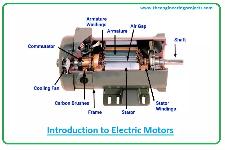
Hi Guys! Welcome you onboard. Interested to know the Introduction to Electric Motors?
Keep reading…
A motor is an electrical machine that converts electrical energy into mechanical energy. It works exactly opposite to generator that converts mechanical energy to electrical energy.
The first electric motors were introduced by Andrew Gordon and Benjamin Franklin in their experiment in 1740 which were nothing but electrostatic devices.
From household to industrial applications, you’ll see motors everywhere. Motors can be divided into two main categories:
AC Motors
DC Motors
Motors in cars, rectifiers, and batteries are a source of direct current motors while motors incorporated in electrical generators, power grid stations, and invertors op ...
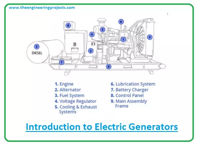
Hi Friends! Good to see you on board. In this post today, I'll walk you through the Introduction to Electric Generators. A generator is a machine that converts mechanical energy to electrical energy that is further used in power grid stations. Gas turbines, steam turbines, water turbines, internal combustion engines are some sources of generating mechanical energy for generators.
In an electric generator, a rectangular coil of electric conductors is used in a changing magnetic field of the poles of a horseshoe type magnet. The current is generated in the coil when it rotates and cuts the magnetic field lines. The electric generator is opposite to the electric motor in the working principle and similar in construction. A generator that comes with ...
Hi Friends! Hope you're well today. I welcome you on board. In this post today, I'll walk you through how software can be customized to fit the need of your company.
Industries require complicated applications that make creating and keeping sensitive data quick and easy. Creating data pertinent to a specific business plays a critical role in today's world.
We are living in a data-driven world. There are options to make the utilization of these complicated applications easier. One of the most popular options for managing the applications is called software as a service or SaaS for short. What SaaS does is provide and manage all the software a business needs.
The software is tailored and customized to the business’s needs. SaaS platform developer ...
Hi Guys! Hope this finds you well. Thank you for clicking this read. In this post today, I'll walk you through the Mosfet what the Mosfet is and how it works.
The MOSFET (Metal Oxide Semiconductor Field Effect Transistor) transistor is a semiconductor device widely used for switching and amplifying electronic signals. The MOSFET is a core of integrated circuit and it can be designed and fabricated in a single chip as they come in small sizes.
The MOSFET carries four-terminal called: source(S), gate (G), drain (D) and body (B) terminals. The body of the MOSFET is connected to the source terminal, making it a three-terminal device like a field-effect transistor. The MOSFET is a common transistor that is used in both analog and digital circuits.
T ...
Hi Friends! Hope you’re well today. I welcome you on board. In this post today, I’ll explain how a 21st century tire industry will revolutionize the market.
Tire changing and purchasing is a controversial issue for many Americans, with non-insurance purchases that are often arguably expensive. This is set to change with the rise of Tire Agent, who TechCrunch highlighted as receiving $5m in new financing in their bid to remove the mystique from tire purchasing and installation. Using smart data, they’re aiming to pull together buyers, sellers, and mechanics across the country and provide a truly equitable purchase map for those in need.
With this data, the industry will be revolutionized, and technology will change how motorists deal with their t ...