Stepper Motor Speed Control using Arduino

Hello everyone! I hope you all will be absolutely fine and fun. Today, I am going to tell you that how to make a simple algorithm for Stepper Motor Speed Control using Arduino. I have already discussed with you about DC Motor Direction Control using Arduino, Matlab and NI LabVIEW. Moreover, I have also discussed the DC Motor Speed Control using Arduino,Matlab and LabView. If you are working on Stepper Motor, then you must have a look at Stepper Motor Direction Control using Arduino, Stepper Motor Direction Control using Matlab and Stepper Motor Direction Control using NI LabVIEW. Now, in this tutorial I will explain you about the program which will helpful for Stepper Motor Speed Control using Arduino. Before going into the details of this tutorial you must have go through my previous tutorials because I am using the same hardware. So, they will be a lot helpful for the better understanding of this tutorial. In this tutorial I will explain you about making an Arduino program for Stepper Motor Speed Control using Arduino with the help of the serial communication. If the stepper motor is rotating at its maximum speed and you are continuously sending the command through the serial port to reduce its speed, it s speed will be reduced in proportion to the number of command sent through the serial port. Similarly the same procedure will be followed to increase the speed of the stepper motor.

Stepper Motor Speed Control using Arduino

In the tutorial Stepper Motor Direction Control using Arduino, I will explain you about making an algorithm to run the stepper motor at different speed. If the stepper motor is already running at its maximum speed and you want want to accelerate it further then nothing will happen to the speed of the stepper motor. If the stepper motor is rotating slowly and you enhance its speed, then the speed of the motor will increase in proportion to the number of accelerating command sent through the serial port.
  • You can download the complete Arduino source code here by clicking on the button below.

Download Arduino Code

  • Download .rar file, extract it and enjoy the complete source code.
Flow Chart
  • I have made a flow chart so that you can easily understand the entire algorithm because sometimes it becomes difficult to understand the algorithm with the help of the source code.
  • Flow chart for the Stepper Motor Speed Control using Arduino is shown in the figure below.
  • First of all we need to start the serial port so that our communication could be started.
  • Then there is a method to check the speed, if the speed is greater than the maximum speed of the stepper motor then the program will wait for the next command.
  • If the stepper motor is not rotating with its maximum speed then we can increase its speed.
  • Similarly if the minimum speed of the stepper motor is reached then the program will rotate for the next commands.
  • If the minimum limit of the speed of the stepper motor is not reached then we have a option to reduce its further.
  • At the end we should close the serial port so that exchange of unnecessary commands through the serial port could be avoided.
Block Diagram
  • Block diagram will be helpful for use for the better understanding of the exchange of information.
  • It tells us that how the information is exchanged sequentially among all the components used.
  • Block diagram is shown in the figure below.
  • Arduino UNO communicates with the L298 motor controller to control the speed of the stepper motor.
  • L298 Motor controller manipulates the Arduino's commands and starts to control the speed of the stepper motor.
Arduino Code Description
In this section of the tutorial Stepper Motor Speed Control using Arduino, I am going to elaborate you about the Arduino source.
  • I have made two different functions for increasing (accelerating) the speed of the stepper motor and for decreasing (deaccelerating) the speed of the stepper motor respectively.
  • I have declared a variable named as count.
  • In Accelerate function, you have to send the command through the serial port to increase the speed of the stepper motor.
  • In this function, I am continuously increasing the value of the count i.e as many times you send the command the speed of the stepper motor will increase continuously.
  • The source code of the Accelerate function is given below.
   void Accelerate_Motor()
   { 
    count=count+10; //Speed will increase continuously as we continue to press H
    if (count>120)  //Speed must not be greater than 120
    {
      count=120;
      }
    Serial.println("Accelerating"); //printing on the serial port
    Serial.println("");//prints blank line on the serial port
    myStepper.step(stepsPerRevolution);//counter clockwise rotation
    myStepper.setSpeed(count); //Updating the speed of the motor
    lcd.setCursor(3,0);//setting LCD cursor
    lcd.print("Acelerating"); //printing on LCD
   }
  • In Deaccelerate function, you have to send the command through the serial port to increase the speed of the stepper motor.
  • In this function, I am continuously reducing the value of the count i.e as many times you send the command the speed of the stepper motor will reduce continuously.
  • The source code of the Deaccelerate function is given below.
void Deaccelerate()
{
  count=count-10; //reducing the speed of the motor
  if (count<20) //speed of the motor must not be less than 20
  {
    count=20;
    }
  Serial.println("Deaccelerating"); // prints on the serial port
  Serial.println(""); //prints blank line on the serial port
  myStepper.step(stepsPerRevolution);
  myStepper.setSpeed(count); //Updating the speed of the motor
  lcd.setCursor(3,0);  //setting cursor on LCD
  lcd.print("Deaccelerating"); //prints the command on LCD
  }
  • In the main source inside the loop I am calling both of these Accelerate and Deaccelerate functions.
  • The executed commands will also be printed on the LCD (Liquid Crystal Diode).
  • The main source code is given below.
#include <LiquidCrystal.h>//Library for LCD
#include <Stepper.h>     //Library for Stepper motor

const int stepsPerRevolution = 255;  

// initialize the stepper library on pins
Stepper myStepper(stepsPerRevolution, 4, 5, 6, 7);
char data;
int count = 120;
//LCD pins assigning
LiquidCrystal lcd(8, 9, 10, 11, 12, 13);
void setup() {
  // set the speed at 60 rpm
  myStepper.setSpeed(60);
  // initialize the serial port:
  Serial.begin(9600);// rate at which the arduino communicates

lcd.begin(20, 4);//LCD type

lcd.setCursor(3,0);//setting LCD cursor and printing on it
lcd.print("Stepper Motor");
lcd.setCursor(6,1);
lcd.print("Speed");
lcd.setCursor(5,2);
lcd.print("Control");
lcd.setCursor(2,3);
lcd.print("via Arduino UNO");

delay(3000);

lcd.clear ();//Clearing the LCD screen

lcd.setCursor(0,2);
lcd.print("www.TheEngineering");
lcd.setCursor(4,3);
lcd.print("Projects.com");
}

void loop() {
  if(Serial.available())
  {
    data = Serial.read(); //Reading the data from serial port
  }
  
    if(data == 'C'){Clockwise();}      //Clockwise rotation
    if(data == 'A'){AntiClockwise();} //Anti-clockwise rotation
    if(data == 'S')                  //stopping the stepper motor
    {
      data = 0; 
      lcd.setCursor(3,0);
      lcd.print("No rotation");
      Serial.println("No rotation");//print on the serial
      }   
     if(data == 'H'){Accelerate_Motor();}
     if(data == 'L'){Deaccelerate();}
}
Complete Hardware Setup
  • In this section of the tutorial, I will show you the complete hardware setup that I have used for this project.
  • Hardware consists of 12V power supply, Arduino UNO, L298 motor controller.
  • When you upload the code to the Arduino board the system will look like the figure shown below.
  • When you press to increase the speed of the stepper motor, the statement accelerating will be printed on the LCD.
  • The printed executed command is printed on the LCD and is shown in the figure below.
  • When you press to reduce the speed of the stepper motor, the statement Deaccelerating will be printed on the LCD.
  • The printed executed command is printed on the LCD and is shown in the figure below.
That is all from the tutorial Stepper Motor Speed Control using Arduino. I hope you all have enjoyed this tutorial. If you face any sort of problem regarding anything you can ask me anytime without even feeling any kind of hesitation. I will try my level best to solve your issues in a better way if possible. I will explore Arduino by making further projects and I will share them with all of you as well in my later tutorials. So, till then, Take Care :)

Stepper Motor Direction Control using Arduino

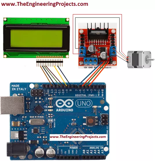
Hello friends! I hope you all will be absolutely fine and having fun. Today, I will elaborate you that how can we make a simple algorithm for Stepper Motor Direction Control using Arduino. In my previous tutorials I made algorithm for DC Motor Direction Control using Arduino, DC Motor Direction Control using Matlab, DC Motor Speed Control using Arduino and DC Motor Speed Control using Matlab. Now, in this tutorial I will control a stepper motor using Arduino by entering the different commands through its serial port. Before going into the detail of this tutorial, you must know the basic difference between stepper and DC motors. DC motors have only two input terminal one is positive and the other one is negative. You just have to provide the power supply and it will start rotating but this is not the case in stepper motor. The stepper motor which I will use in this tutorial, has six pins out of which four pins provide pulses or steps and the other two pins are power pins. So, in this tutorial I will control this six pins stepper motor using L298 motor controller and Arduino UNO board. Basically we can use stepper motor where precision is required. Stepper motor has wide range of applications e.g robotics, CNC machines, home automation etc. In simple word, we can say that stepper motor can be used where there is a need to move at particular angle. So, let's get started with Stepper Motor Direction Control using Arduino:

Stepper Motor Direction Control using Arduino

In this tutorial we will learn how to make a program for Stepper Motor Direction Control using Arduino by sending dfferent commands from the serial port. First of all, I am going share the list of components used for this mini project.
  • Arduino UNO
  • Stepper motor (6 wire)
  • L298 Motor Controller (H-Bridge)
  • Voltage Regulator (7805)
  • 1000uF
  • Jumper Wires
  • Solderig Iron
  • Soldering Wire
I want to tell you a bit about the stepper motor because all the other components are discussed in detail in DC Motor Direction Control using Arduino.
Stepper Motor
Basically, stepper motors are like the DC motors that rotate in discrete steps. They have multiple arranged coils and they are usually known as phases. Motor will rotate one step at a time if we energize each phase sequence. High levels of precision can be achieved by controlling the stepper motor with computer. Steppers motors are available in the market in many different sizes. The speed of the stepper motor is controlled by frequency of pulses generated. They have wide range of applications like hard disk drives, robotics, telescope, antenna, toys etc. A six wire stepper motor is shown in the figure below.  
  • You can download complete source code for Stepper Motor Direction Control using Arduino by clicking the below button:

Download Arduino Source Code

Selection of Wires
  • I have used 6 wire stepper motor and each wire has its own function.
  • I have first divided these six wires into two pair.
  • Each pair is consisting of three wires out of which one wire is common and the other two generate pulses.
  • The two pair of three wires are shown in the figure below.

  • Then, I have chosen a common wire in each pair from which the resistance to the other two wires is common.
  • I have checked the resistance from the common wire to the both of the other wires of the same pair.
  • I found that the resistance from the common wire to both of the other wires is same.
  • We can see in the figure above the blue, pink and white wires belong to the same pair out of which white is a common wire.
  • Here is the screen shot of the figure when I found the resistance between white and blue wire and I found it to be 8.0 ohms.
  • The screen shot of the above steps is shown in the figure below.
  • After that. I checked the resistance between white and pink wire and found it to be 8.1 which is almost the same as 8.0 so, this shows that the white wire is common to both of the blue and pink wire.
  • Here is the screen shot of the above step.
  • Then I found the resistance between pink and blue wire and it was 15.6 which is exactly the double of the earlier resistance.
  • It is shown in the figure below.
  • I have connect the both common wires as shown in the figure below.

  • Here's the video in which I have discussed it in detail How to identify the wires of Stepper Motor:
  • The remaining four wires are used to generate pulses which are also know as steps
  • I have connected theses four wires to the output pins OUT1, OUT2, OUT3 and OUT4 of the L298 micro controller.
  • Input pins of L298 micro controller In1, In2, In3 and In4 are connected to the pin no 7, 6, 5 and of the Arduino UNO's board respectively.
Note:

I have also controlled the stepper motor using PIC micro controller so I would suggest all of you to first go through that tutorial before going into the details of this tutorial.

Block Diagram
  • I have made a simple block diagram for Stepper Motor Direction Control using Arduino, which will be helpful to clearly understand the algorithm and the assembling of the components of Stepper Motor Direction Control using Arduino.
  • The screenshot of the block diagram is shown in the figure below.
  • First of all we need a power supply to run the project properly.
  • Arduino reads the commands from the serial port and sends to the L298 motor driver to rotate the stepper motor.
  • The commands got printed on the LCD (Liquid Crystal Display).
Arduino Source Code Description
  • The main function of the Stepper Motor Direction Control using Arduino is given below.
#include <LiquidCrystal.h>//Library for LCD
#include <Stepper.h> //Library for Stepper motor

const int stepsPerRevolution = 255;  

// initialize the stepper library on pins
Stepper myStepper(stepsPerRevolution, 4, 5, 6, 7);
char data;
//LCD pins assigning
LiquidCrystal lcd(8, 9, 10, 11, 12, 13);
void setup() {
  // set the speed at 60 rpm
  myStepper.setSpeed(60);
  // initialize the serial port:
  Serial.begin(9600);

lcd.begin(20, 4);//LCD type

lcd.setCursor(3,0);//setting LCD cursor and printing on it
lcd.print("Stepper Motor");
lcd.setCursor(5,1);
lcd.print("Direction");
lcd.setCursor(5,2);
lcd.print("Control");
lcd.setCursor(2,3);
lcd.print("via Arduino UNO");

delay(3000);

lcd.clear ();//Clearing the LCD screen

lcd.setCursor(0,2);
lcd.print("www.TheEngineering");
lcd.setCursor(4,3);
lcd.print("Projects.com");
}

void loop() {
  if(Serial.available())
  {
    data = Serial.read(); //Reading the data from serial port
  }
  
    if(data == 'C'){Clockwise();}//Clockwise rotation
    if(data == 'A'){AntiClockwise();}//Anti-clockwise rotation
    if(data == 'S')//stopping the stepper motor
    {
      data = 0; 
      lcd.setCursor(3,0);
      lcd.print("No rotation");}
    
}
  • In the code given above we have first initialized the LCD and Stepper motor libraries.
  • Then, I assigned stepper motor pins at which it is connected to the Arduino.
  • After that I initialized the LCD pins at which it is connected to Arduino UNO.
  • Then I have made three different if statements, for the clockwise, for the anti clockwise rotation and for the no rotation.
  • Then in the loop I called clock wise and anti clockwise functions whose source code will be give and explained below.
  • Then, I cleared the serial data in order to stop the rotation of the motor.
  • The source code of the clockwise function is given below.
void Clockwise()//function for clockwise rotation
{
    Serial.println("clockwise"); //printing on the serial port
    Serial.println("");//prints blank line on the serial port
    myStepper.step(stepsPerRevolution);//counter clockwise rotation
    lcd.setCursor(3,0);//setting LCD cursor
    lcd.print("Clockwise"); //printing on LCDa
}
  • The source code for the anti clockwise function is given below.
void AntiClockwise()//function for anti clockwise rotation
{
  Serial.println("anti-clockwise");//print on the serial
  Serial.println("");//prints a blank line on the serial
  myStepper.step(-stepsPerRevolution);//clockwise movement
  lcd.setCursor(3,0);//setting LCD cursor
  lcd.print("Anti-clockwise");//printing on LCD
}
  • Now, open your Arduino software, just copy and paste the source code given above.
  • Run the program and open the Serial Port at the top right of the Arduino software.
  • Now, when you enter the command stepper motor will start running in clockwise direction.
  • If you send the command through the serial port stepper motor will start to rotate in counter clockwise direction.
  • If you send the command the rotation of the stepper motor will be stopped.
Actual Hardware Setup
  • The actual hardware operating setup for Stepper Motor Direction Control using Arduino is given in the figure below:
  • Now, if you send the command  through the serial port the stepper motor will start to rotate in clockwise direction and the command will also be printed on the LCD.
  • The screenshot of the printed command on LCD is shown in the figure below.
  • Now, if you send the command  through the serial port the stepper motor will start to rotate in anti clockwise direction and the command will also be printed on the LCD.
  • The screenshot of the printed command on LCD is shown in the figure below.
  • Now, if you send the command  through the serial port the stepper motor will show no more rotation and the command will also be printed on the LCD.
  • The screenshot of the printed command on LCD is shown in the figure below.
  • Here's the complete video demonstration of Stepper Motor Direction Control using Arduino, I hope it will help as well:
That's all from the tutorial Stepper Motor Direction Control using Arduino. I hope you enjoyed this tutorial. If you face any sort of problem, you can ask me anytime without feeling any kind of hesitation. I will try my level best to solve your problem in a better way if possible. I will explore Arduino by making different projects on it. Till then, Take care :)

DC Motor Speed Control using Arduino

Hello friends! I hope you all will be absolutely fine and having fun. Today, I am going to share my knowledge about how can you make a simple program for DC Motor Speed Control using Arduino UNO. In my previous tutorial, DC Motor Direction Control using Arduino, I have just controlled the DC motor in both directions at constant speed using Arduino. I have also performed the DC Motor Direction Control in Matlab by sending different commands through serial port from Matlab and LabVIEW to the Arduino and then controlled the direction of rotation of DC motor. But in this tutorial I will rotate the same DC motor at variable speed in both clockwise and anti clockwise directions. In my previous tutorial, we have seen that input pins In1 In2 of motor control driver L298 (H-Bridge) are useful to control the direction of rotation of the DC motor. In this tutorial, I have controlled its speed as well by providing different voltage levels at the enable pin of the DC motor control driver L298. It will be helpful to vary the speed of the DC motor in either clockwise or in anti clockwise direction. So, let's get started with DC Motor Speed Control using Arduino UNO:

DC Motor Speed Control using Arduino UNO

In this tutorial we will learn that how to make an algorithm for DC Motor Speed Control using Arduino UNO. Speed control of any motor is always done y Pulse Width Modulation, abbreviated as PWM. PWM pulse can be generated using Arduino and L298 Enable Pin is used to get that PWM pulse and then it controls the motor speed accordingly. Before going into the further details I would like to tell you about the concept of PWM for controlling DC motor. Moreover, you can download the complete Arduino code for DC Motor Speed Control using Arduino by clicking the below button: Download Arduino Source Code
Pulse Width Modulation (PWM)
PWM stands for Pulse Width Modulation. It basically describes the type of the digital signal. PWM technique is an excellent technique to control the analog circuits with microcontroller's digital PWM output. In this technique we can get analog results with the digital means. Digital control is used to create square wave. This pattern can vary voltages between full on i.e. 5V and full off i.e. 0V. The duration of on time i.e. when the the signal is present is known as pulse width. PWM waves for the different duty cycles are shown in the figure below. Duty cycle is basically the proportion of the time during which a system is operated. It can be expressed as a percentage. For example motor rotates for 1 second out of 100 seconds, it duty cycle can be represented as 1/100 or as 1%. For Arduino software coding the command analogWrite(255) shows the maximum i.e. 100% duty cycle. To achieve 50% duty cycle we have to update this command to analogWrite(127). Arduino UNO's pin no 3, 5, 6,10 and 11 are used as PWM pins. In this project we can control the speed of the DC motor by providing high and low voltages to the enable pin of the motor control driver L298. For example, if a motor rotates with the maximum speed and 100% duty cycle at 12V and we provide it with the 6V then it will rotate with the half of the initial speed having 50% duty cycle.
Motor Controller L298
The pins EnA and EnB of the motor controller L298 are used as the PWM pins. We can rotate the DC motor at different speed providing different high and low voltage levels to these pins of the motor control driver. If we start to reduce the maximum voltage at which the motor rotates at maximum speed, the speed of the motor also starts to reduce. In this way these enable pins are helpful to control the speed of the DC motor.
Algorithm design and descrition
In this section of the tutorial DC Motor Speed Control using Arduino UNO, I am going to explain you about designing as well as a detailed description of the designed algorithm. I will tell you about the entire algorithm in step by step procedure. Note:Since you are working on the DC motor so you must also have a look at my previous tutorials, they will be helpful for you to simulate this project as well. Open your Arduino software, copy and paste the source code given below in your software.
#include <LiquidCrystal.h>
//Keyboard Controls:
//
// C - Clockwise
// S - Stop
// A - Anti-clockwise

// Declare L298N Controller pins
// Motor 1
int count=255;
int dir1PinA = 2;
int dir2PinA = 5;
int speedPinA = 6; // PWM control
LiquidCrystal lcd(8, 9, 10, 11, 12, 13);

void setup() { 
 
Serial.begin(9600); // baud rate

lcd.begin(20, 4);
lcd.setCursor(5,0);
lcd.print("DC Motor");
lcd.setCursor(5,1);
lcd.print("Direction");
lcd.setCursor(5,2);
lcd.print("Control");
lcd.setCursor(2,3);
lcd.print("via Arduino UNO");

delay(3000);

lcd.clear ();

lcd.setCursor(0,2);
lcd.print("www.TheEngineering");
lcd.setCursor(4,3);
lcd.print("Projects.com");
//Define L298N Dual H-Bridge Motor Controller Pins

pinMode(dir1PinA,OUTPUT);
pinMode(dir2PinA,OUTPUT);
pinMode(speedPinA,OUTPUT);

analogWrite(speedPinA, 255);//Sets speed variable via PWM 

}

void loop() {

// Initialize the Serial interface:

if (Serial.available() > 0) {
int inByte = Serial.read();
int speed; // Local variable

switch (inByte) {

case 'C': // Clockwise rotation
//analogWrite(speedPinA, 255);//Sets speed variable via PWM 
digitalWrite(dir1PinA, LOW);
digitalWrite(dir2PinA, HIGH);
Serial.println("Clockwise rotation"); // Prints out “Motor 1 Forward” on the serial monitor
Serial.println("   "); // Creates a blank line printed on the serial monitor
//lcd.clear();
lcd.setCursor(0,0);
lcd.print("Clockwise rotation");
break;

case 'S': // No rotation
//analogWrite(speedPinA, 0); // 0 PWM (Speed)
digitalWrite(dir1PinA, LOW);
digitalWrite(dir2PinA, LOW);
Serial.println("No rotation");
Serial.println("   ");
//lcd.clear();
lcd.setCursor(0,0);
lcd.print("No rotation");
break;

case 'H': //Accelrating motor
count=count+20;
  if (count>255)
  {
  count =255;
  }
  analogWrite(speedPinA,count);
  delay(50);

//digitalWrite(dir1PinA, LOW);
//digitalWrite(dir2PinA, HIGH);
Serial.println("Motor is accelrating slowly");
Serial.println("   ");
Serial.println(count);
lcd.setCursor(0,0);
lcd.print("Motor is accelrating");
break;

case 'L': //Deaccelrating motor
count=count-20;
  if (count<20)
  {
  count=20;
  }
  analogWrite(speedPinA,count);
  delay(50);

//digitalWrite(dir1PinA, LOW);
//digitalWrite(dir2PinA, HIGH);
Serial.println("Motor is deaccelrating slowly");
Serial.println("   ");
Serial.println(count);
lcd.setCursor(0,0);
lcd.print("Motor Deaccelrates");
break;

case 'A': // Anti-clockwise rotation
//analogWrite(speedPinA, 255); // Maximum PWM (speed)
digitalWrite(dir1PinA, HIGH);
digitalWrite(dir2PinA, LOW);
Serial.println("Anti-clockwise rotation");
Serial.println("   ");
//lcd.clear();
lcd.setCursor(0,0);
lcd.print("Anti-clockwise");
break;

default:
// Turn off the motor if any other key is being pressed
for (int thisPin = 2; thisPin < 11; thisPin++) {
digitalWrite(thisPin, LOW);
}
Serial.println("Wrong key is pressed");
//lcd.clear();
lcd.setCursor(0,0);
lcd.print("Wrong key is pressed");
  }
    }
      }
  • In the previous tutorials, DC Motor Direction Control using Arduino and DC Motor Direction Control using Matlab we have learnt that how to control the direction of the DC motor.
  • We used the commands C, A and S for the clockwise rotation, anti clockwise rotation and stopping the motor respectively.
  • In this tutorial, we have added two further commands and for accelerating and de-accelerating the DC motor.
  • If we send the command H different times consecutively the speed of the motor will increase continuously.
  • If we send the command different times consecutively, the speed of the motor will start to decrease.
  • Now, upload the source code to your Arduino UNO's board.
  • Open the serial monitor at the top right of the Arduino Software.
  • And enter the commands in serial monitor periodically as explained above.
Actual Hardware Setup
  • When we enter the command in the serial monitor of the Arduino software. Motor will start rotating in the clockwise direction and a statement Clockwise rotation will be printed on serial port.
  • The same statement will be printed on the LCD as well as shown in the figure below.
  • When we enter the command in the serial monitor of the Arduino software. Motor will start rotating in the anti clockwise direction and a statement Anti clockwise rotation will be printed on serial port.
  • The same statement will be printed on the LCD as well as shown in the figure below.
  • When we enter the command in the serial monitor of the Arduino software. Motor will start accelerating and a statement Motor is accelerating will be printed on serial port.
  • The same statement will be printed on the LCD as well as shown in the figure below.
  • When we enter the command in the serial monitor of the Arduino software. Motor will start to deaccelerate and a statement Motor Deaccelerates will be printed on serial port.
  • The same statement will be printed on the LCD as well as shown in the figure below.
Thats all from the tutorial DC Motor Speed Control using Arduino UNO. I hope you have enjoyed this tutorial. If you face any sort of problem, you can ask me anytime without feeling any kind of hesitation. I will further explore my knowledge about Arduino projects in my later tutorials. Till then, Take care :)

DC Motor Direction Control using Arduino

Hello friends! I hope you all will be absolutely fine and having fun. Today, I am going to share my knowledge with all of you about how to make a simple program for DC Motor Direction Control using Arduino. The word DC is basically an abbreviation of Direct current. So, a direct current motor is commonly used motor having two input terminals, one is positive and the other one is negative. If we connect these terminals with the voltage supply the motor will rotate. If you change the polarity then motor will rotate in opposite direction. You should also have a look at Difference between DC & AC Motors to get a better idea about these motors. DC motor has a lot of applications. You can use it in automation projects, for controlling static as well as mobile robots, in transport system, in pumps,fans,bowers and for industrial use as well. In this tutorial, I will do the DC Motor Direction Control using Arduino and L298 motor controller. Moreover, I have also used LCD which will give us the status of our DC Motor i.e. whether its moving in clockwise direction or anticlockwise. In my later tutorial I will control the same DC motor using NI LabVIEW 2015 and MATLAB. I have added the next tutorial on this project in which I have done the DC Motor Direction Control in MATLAB so in that project, I have used the same hardware but instead of controlling it from Arduino I have controled it using MATLAB so you must have a look at that tutorial.

DC Motor Direction Control using Arduino

In this tutorial, I will make a simple program to do the DC Motor Direction Control using Arduino. Arduino is basically an amazing micro controller and is very easy to use because it is an open source device. So, it is a student friendly device. You can also write Arduino programs for different purpose. Arduino is also a cost efficient device in comparison to the other micro-controllers e.g. raspberyy pi, NI-myRIO, galileo, single board RIO etc. First of all I prepared my complete hardware setup. Then I made a program and interfaced it with the hardware. We will discuss all the steps in detail below. The logic is pretty simple i.e. Arduino has to send commands to L298 motor controller and then L298 decides the DC Motor Direction Control by manipulating the Arduino commands. Before going into the detail, I want to show you the list of components required. You can download complete Arduino source file here:

Download Arduino Source Code Note: If you are working on DC Motor then you should also have a look at these Proteus Simulations:

Components List & Description

Here's the complete list of the components required for designing DC Motor Direction Control using Arduino: So, now let's discuss the main components for this project individually so that you get better idea of why these components are used in this DC Motor Direction Control using Arduino:
Arduino UNO
Arduino UNO is basically the back bone of this DC Motor Direction Control Project. It controls and leads the whole project. In this project, Arduino reads the commends from serial port and sends to L298 motor controller IC in order to control the direction of rotation of the DC motor. So, the Arduino has overall major control over the whole project.
Motor Controller L298
Motor Controller is used to control the direction of DC motor. It consists of an L298 motor driver IC which is capable of rotating the motor in both clockwise and anti clockwise directions by switching its pins from HIGH to LOW and vise versa. Moreover, it needs +12V, GND and +5V in order to power it up. So, we will design a voltage regulator which will step down 12V to 5V. So, let's have a look at this voltage driver in next part:  
Voltage Regulator
Voltage regulator is also the part of this design. In our daily life, we need to step up or to step down the voltages according to the requirements. Requirements vary with the different purpose. Small electronics components like micro-controller, LED, LCD etc. So the main purpose of voltage regulator is to step down the voltage from 12V to just 5V in order to fulfill the requirements of the electronic components. Step down transformer can also be used instead of voltage regulator. Due to the huge structure and cost we prefer to use voltage regulator. You should read How to Design a 5V Power Supply in Proteus to get better idea about this voltage regulator. The circuit diagram of the designed voltage regulator is shown in the figure below.
DC Motor
DC motor is the essential part of the different projects and our daily life. for example if we want to automate our house doors i.e if we want to open and close the doors automatically by detecting the person, motor plays a vital role here. Similarly in robotics, vacuum, blowers and air conditioners, DC motor has a wide range of applications. LED is used here to show whether the designed circuit is working properly or not. Like in mobile phones and laptops as we connect the charger it shows the charging indication. So, we must need some indication that everything is going fine and the circuit is working properly.
Jumper Wires
Jumper wires are used to make the connections between all of the components. Use small pieces of the jumper wires in order to give a better look to the designed circuit. If you are using longer wires for the connections, it will create complexity and causes many problems while operating the circuits.
Power Supply
12V power supply is used as the main power supply. As we know, to operate any of the electronic components or electronic appliances we must need the main power supply. Power supply can vary according to the power consumption of the electronic equipment. Here I am using a 12V DC power supply because it is a small and simple project with minimum power requirements.
LCD 20x4
LCD is used to visualize the commands sent to the serial port. It basially display us that which function is being performed at a particular time. A 20×4 LCD is used and is shown in the figure below. If you haven't worked on LCD before, then you should have a look at Circuit Designing of LCD with Arduino in Proteus ISIS.
Assembling of the Components
Here are the few steps followed while designing this DC Motor Direction Control using arduino:
  • Connect the terminals of the DC motor with the output pins (OUT1 and OUT2) of L298 motor controller.
  • Connect L298 motor controller's pin IN1 and IN2 with the Arduino UNO's pin 2 and 5 respectively.
  • Now, connect ENA pin of L298 motor controller to the Arduino's pin 9.
  • Connect the power supply to turn on the circuit.
  • Make sure that you have supplied 12V, 5V and GND properly to the L298 motor controller.  
Circuit Diagram
Completely Assembled Diagram

Arduino Code Designing

After making all the connections properly, open your Arduino source code. If you are using Arduino for the first time then you should have a look at Installation of Arduino Driver in Windows.
  • Attach the Arduino board with your PC and go to Search->Device Manager as shown in the figure below.
  • Select the device manger and you can see different options here like Batteries, bluetooth radios, keyboards, monitors, ports etc.
  • Open the Ports(COM & LPT) as shown in the figure below.
  • See the COM Port supported by Arduino Board which COM5 in this case.
  • Now open the Arduino software and go to Tools and select the Arduino board and the COM port properly.
  • The description is shown in the figure given below.
  • Just copy and paste the source code given below.
#include <LiquidCrystal.h>
//Keyboard Controls:
//
// C - Clockwise
// S - Stop
// A - Anti-clockwise

// Declare L298N Controller pins
// Motor 1
int dir1PinA = 2;
int dir2PinA = 5;
int speedPinA = 7; // PWM control
LiquidCrystal lcd(8, 9, 10, 11, 12, 13);

void setup() { 
 
Serial.begin(9600); // baud rate

lcd.begin(20, 4);
lcd.setCursor(5,0);
lcd.print("DC Motor");
lcd.setCursor(5,1);
lcd.print("Direction");
lcd.setCursor(5,2);
lcd.print("Control");
lcd.setCursor(2,3);
lcd.print("via Arduino UNO");
//Define L298N Dual H-Bridge Motor Controller Pins

pinMode(dir1PinA,OUTPUT);
pinMode(dir2PinA,OUTPUT);
pinMode(speedPinA,OUTPUT);

}

void loop() {

// Initialize the Serial interface:

if (Serial.available() > 0) {
int inByte = Serial.read();
int speed; // Local variable

switch (inByte) {

case 'C': // Clockwise rotation
analogWrite(speedPinA, 255);//Sets speed variable via PWM 
digitalWrite(dir1PinA, LOW);
digitalWrite(dir2PinA, HIGH);
Serial.println("Clockwise rotation"); // Prints out “Motor 1 Forward” on the serial monitor
Serial.println("   "); // Creates a blank line printed on the serial monitor
lcd.clear();
lcd.setCursor(0,0);
lcd.print("Clockwise rotation");
break;

case 'S': // No rotation
analogWrite(speedPinA, 0); // 0 PWM (Speed)
digitalWrite(dir1PinA, LOW);
digitalWrite(dir2PinA, LOW);
Serial.println("No rotation");
Serial.println("   ");
//lcd.clear();
lcd.setCursor(5,1);
lcd.print("No rotation");
break;

case 'A': // Anti-clockwise rotation
analogWrite(speedPinA, 255); // Maximum PWM (speed)
digitalWrite(dir1PinA, HIGH);
digitalWrite(dir2PinA, LOW);
Serial.println("Anti-clockwise rotation");
Serial.println("   ");
//lcd.clear();
lcd.setCursor(3,2);
lcd.print("Anti-clockwise");
break;

default:
// Turn off the motor if any other key is being pressed
for (int thisPin = 2; thisPin < 11; thisPin++) {
digitalWrite(thisPin, LOW);
}
Serial.println("Wrong key is pressed");
//lcd.clear();
lcd.setCursor(0,3);
lcd.print("Wrong key is pressed");
  }
    }
      }
  • Now, upload the source code onto the Arduino UNO board as shown below.
  • In the above figure shows that the source code is uploading to the Arduino board.
   
  • Done uploading shows that the source code has been uploaded successfully to the Arduino borad.
  • Now, go to the Serial Monitor on the top right corner of the Arduino software.
  • Press C, you can see the DC motor is rotating in the clockwise direction and statement Clockwise rotation will be printed on the Serial Monitor.
  • Now, press S, the DC motor will stop and a statement No rotation will be print on the Serial Monitor.
  • If you want to rotate DC motor in anti-clockwise direction, press A then, the statement Anti-Clockwise rotation will be printed on the Serial Monitor.
  • I have made the logic in such a way that if you press any of the other buttons the DC motor will stop in reaction to that and the statement Wrong key is pressed will be printed on the Serial Monitor.
  • All of the above steps are shown in the figure shown below.
   

Final Testing of DC Motor Direction Control using Arduino

  • The screenshot of the actual circuitry for DC Motor Direction Control using Arduino is shown in the below figure:
  • You can see in the above figure that we have attached Arduino UNO board with L298 Motor Driver and then we have attached DC Motor with Arduino UNO and LCD is used to show the current movement of Motor.
  • Moreover we have also designed a small circuit which I have mentioned above and named as Voltage regulator, and it is used to step down 12V into 5V.
So, that's all from the tutorial DC motor Direction Control using Arduino. I hope you enjoyed this tutorial. In my next tutorials, I will interface this project with LabView and MATLAB. If you face any sort of problem, you can freely ask me anytime without feeling any kind of hesitation. So, will see you guys in next tutorial. Till then Take  care :)

Interfacing of Arduino with GLCD

Hello friends, I hope you all are doing great and having fun with your lives. In today's tutorial, I am going to share How to interface Arduino with GLCD. I am gonna design a Proteus Simulation in which I will interface Arduino GLCD together. GLCD is also called Graphical LCD so today we are gonna do some designing on the LCD. The GLCD I am going to use is ks0108 and its model in Proteus is LGM12641BS1R and I have shared the complete Simulation along with Arduino Code below for download. But I would suggest you to design it on your own so that you could get the most out of it. If you haven't worked on the LCD before then I would suggest you to read How to Interface Simple LCD with Arduino. Moreover, I am quite happy to announce that we have started TEP Forum so if you guys have any questions related to your engineering projects then ask in our forum and we will try our best to resolve your issues. Anyways, let's get back to our today's tutorial and interface Arduino GLCD in Proteus ISIS.

Interfacing of Arduino with GLCD

  • First of all, you can download the Proteus Simulation and Arduino Code for Interfacing of Arduino with GLCD, by clicking the below button:

Download Code & Simulation

  • Now let's design it so that you can understand how this is working.
  • So, first of all design a Proteus Simulation for Interfacing of Arduino with GLCD, as shown in below figure:
Note: Proteus doesn't have Arduino in its database so you need to install this Arduino Library for Proteus if you wanna use Arduino in Proteus.
  • Now upload the below Arduino code in your Arduino Software and Get your Arduino Hex File, which we are gonna upload in our Proteus Arduino.
  • Here's the Arduino Code for Interfacing of Arduino with GLCD:
Note:
  • You also have to install the GLCD Library for Arduino, I have added this library in the above package so when you download it first of all install this library in Arduino Software.
#include <glcd.h>
#include "fonts/allFonts.h"        
#include "bitmaps/allBitmaps.h"    

Image_t icon;

gText textArea;              
gText textAreaArray[3];     
gText countdownArea =  gText(GLCD.CenterX, GLCD.CenterY, 1, 1, Arial_14); 

unsigned long startMillis;
unsigned int  loops = 0;
unsigned int  iter = 0;
         int  theDelay = 20; 

void setup()
{
  GLCD.Init();
  if(GLCD.Height >= 64)   
    icon = ArduinoIcon64x64;  
  else
    icon = ArduinoIcon64x32;  

  GLCD.ClearScreen(); 

  GLCD.SelectFont(System5x7, BLACK); 
  GLCD.CursorTo(2, 2);
  GLCD.print("The Engineering");
  GLCD.CursorTo(5, 3);
  GLCD.print("Projects");
}


void  loop()
{  
  
}
  • So, now if everything goes fine then when you run your Proteus Simulation of Arduino with GLCD, you will get results as shown in below figure:
  • So, what we have done is we just printed our blog name on the GLCD using Arduino.
  • Now, in the package you download I have also added another example which when you upload will give you a demo of GLCD.
  • Here's the results of the second example, I have added some screenshots:
  • So, that's how you can interface Arduino with GLCD and can design anything you want.
  • It's really very easy but quite lengthy, I must tell.
  • I have designed this video which will help you in better understanding:
So, that's all about Interfacing of Arduino with GLCD and I hope I have helped you guys in some ways. So, will meet you guys in the next tutorial. Till then take care and have fun !!! :)

How to use Arduino PWM Pins

Hello friends, I hope you all are doing great. In today's tutorial, I am going to show you How to use Arduino PWM Pins. It's the next tutorial in our new Arduino Tutorial for Beginners series. We will design a small code in which we will be controlling a dc motor's speed using the Arduino PWM Pins but before going into the details, let me first give you an introduction to Arduino PWM Pins because without understanding the PWM, which is the abbreviation of Pulse Width Modulation, you won't be able to understand How to use Arduino PWM Pins. In our previous tutorial, we have seen How to use analogWrite in Arduino and I have told you in that tutorial that we use this command for PWM as well. So, today we will have a look at How to do that. PWM is an abbreviation of Pulse Width Modulation, its a simple technique in which we just modulate the width of a pulse to get our required results. Suppose, we have a 12V DC signal but my requirement is to get the 6V instetad of 12V so here what I need is PWM. I will use PWM on 12V signal and then reduce it to 6V. Another important thing related to PWM is duty cycle. Duty Cycle is the percentage for which the pulse remains HIGH. For example, if the pulse is of 12V and you turn it into 6V using PWM then the duty cycle of PWM is 50%. I have posted many tutorials on PWM for example you should have a look at How to Generate PWM in 8051 Microcontroller. In this tutorial, I have explained in detail about PWM signal. Moreover, you can also have a look at DC Motor Speed Control using Arduino in which I have controlled the speed of DC Motor with LDR Sensor. Anyways, let's get back to How to use Arduino PWM Pins:

How to use Arduino PWM Pins ???

  • You can download the complete simulation along with its Arduino code for Arduino PWM by clicking the below button:

Download Simulation & Cod

  • First of alll, we should know which pins of Arduino can be used for PWM purposes.
  • So, if you have a look at the below figure, its an Arduino UNO and all the pins of Arduino UNO which has this sign "~" in front of them are PWM pins.
  • If you have a look at the above Arduino UNO image then you can see that "~" this sign is placed in front of six pins.
  • So, Arduino UNO PWM Pins are:
  • Pin # 3
  • Pin # 5
  • Pin # 6
  • Pin # 9
  • Pin # 10
  • Pin # 11
  • Using these PWM Pins, you can create the PWM pulse which we are gonna do rite now. :)
  • So, design a simulation in Proteus as shown in the below figure:
  • As you can see in the above figure that I have used LDR Sensor with Arduino UNO and I have plotted the PWM output coming from Arduino UNO on the oscilloscope.
  • For PWM output the command used in Arduino is:

analogWrite(PWM_Pin, PWM_Value);

  • As, you can see its just an analog Write command and using it you can write any value to the PWM Pin ranging from 0 to 255.
  • At 0 the duty cycle of PWM will be 0% and at 255 it will be 100%.
  • So, what I did in the above example is I just take the analog value coming from LDR and then transferred it to PWM Pin of Arduino UNO.
  • So, now upload the below code in your Arduino board:
int PWMControl= 6;
int PWM_Input = A0;

int PWM_Value = 0;

void setup() {
    pinMode(PWMControl, OUTPUT);
    pinMode(PWM_Input, INPUT);
    Serial.begin(9600);
}

void loop() 
{
    PWM_Value = analogRead(PWM_Input);
    PWM_Value = map(PWM_Value, 0, 1023, 0, 255);
    analogWrite(PWMControl, PWM_Value);
}
  • So, now Get your Arduino Hex File and upload it in your Proteus software.
  • You will also need to download Arduino Library for Proteus, if you wanna use this Arduino UNO in Proteus.
  • Now, if everything goes fine then you will get results as shown in below figure:
  • Now you can see in the above figure that I have shown the PWM pulse in the oscilloscope and now when you change the LDR value then this pulse's PWM will also change.
  • You can download the complete simulation with Arduino code by clicking the button above.
  • If you have any problems or issues in this Arduino PWM tutorial then let me know in comments.
I hope you have enjoyed today's post on Arduino PWM Pins and I would suggest you to have a look at DC Motor Speed Control using Arduino, it will help you a lot in understanding the basic concept of Arduino PWM. So, that's all about Arduino PWM, will see you guys in the next tutorial. Till then take care and have fun !!! :)

Arduino Tutorial for Beginners

Hello friends, I hope you all are fine and having fun with your lives. Today, I am going to share a complete Arduino Tutorial for Beginners because I was having a lot of requests about it. Reader were asking the same question that they are new to Arduino and how should they start so if you are beginner to Arduino and you don't have any idea How to learn it then you should read the below tutorials. I have posted all the basic Arduino Tutorial for Beginners already so in today's tutorial I am just gonna arrange them and must ask you to read them one by one from top to bottom and at then end you will really be able to design any kind of project on Arduino. So, let's get started with Arduino Tutorial for Beginners:

Arduino Tutorial for Beginners

Before going into the practical Arduino Programming, you must first read some theoretical knowledge about Arduino which will really help you out in your Arduino Projects. So these are the basic Arduino tutorial which I will post here step by step: What is Arduino ? First of all, you should read this tutorial in which I have given the basic introduction of Arduino. This tutorial is essential one, if you are new to Arduino. Arduino Vs Raspberry Pi Next thing you should read is Arduino Vs Raspberry Pi,  its not that important but its always good to have a look at alternatives. Installation of Arduino Driver in Windows Now, I suppose that you know the basics of Arduino and have got your Arduino UNO in your hand and are ready to install Arduino Drivers in your Windows. Arduino Library for Proteus Next thing you need to read is How to use Arduino Library for Proteus. Using this library you can easily simulate your Arduino boards in Proteus software. Getting Started with Arduino Software Now you have the basic idea of Arduino board and you know How to use it in Proteus, the next thing you need to do is to have some understanding about Arduino software.

Basic Arduino Commands

Now, that you have understood the basics of Arduino and its programming so now let's have a look at some Basic Arduino Commands and I would suggest you to test these commands in Proteus on your own so that you do mistakes and get some knowledge from them. Anyways, let's continue with these Basic Arduino Commands: Getting Started with Arduino Programming After having a look at the Arduino software, next thing you need to do is to read about Getting Started with Arduino Programming. Arduino Data Types Then we have a tutorial at Arduino Data Types in which we have explained in detail all the Data Types of Arduino. How to use pinMode in Arduino How to use pinMode in Arduino is the next tutorial which you must read so that you have an idea about how to make pins input or output. How to use DigitalRead in Arduino How to use DigitalRead in Arduino is the next tutorial which you must read so that you have an idea about how to use the digital Pins of Arduino. How to use DigitalWrite in Arduino How to use DigitalWrite in Arduino is the next tutorial which you must read so that you have an idea about how to use the digital Pins of Arduino. How to use AnalogRead in Arduino How to use AnalogRead in Arduino is the next tutorial and I have explained here how to read the status of analog Pins. How to use AnalogWrite in Arduino Analog Write is used to update the status of analog Pins as well as PWM Pins. Here we will discuss this command and in next tutorial we will have a look at PWM Pins. How to use Arduino PWM Pins How to use DigitalRead in Arduino is the next tutorial which you must read so that you have an idea about how to use the digital Pins of Arduino. A Simple Arduino LED Example First of all, you should have a look at A Simple Arduino LED Example in which I have designed a simple example in Proteus and blinked the LED at Pin # 13 of Arduino. How to write Arduino code Next article you should have a look at is How to write Arduino code, in this tutorial I have explained how to write arduino code efficiently. At the end, I would suggest you to have a look at this list of Arduino Projects in which I have given all the Arduino Projects which are posted on our blog, so once you get trained in Arduino then you can try those projects and can get pro in Arduino.  

Arduino Data Types

Hello everyone, I hope you all are fine and having fun with your lives. In today's post, I am going to share all about Arduino Data Types. Arduino Data Types play an important role in Arduino Programming and I have discussed them a little in my tutorial on How to do Arduino Programming. But today, we are gonna discuss it in more detail. I hope you guys are gonna enjoy from them and are gonna get benefit using them. Before going any further I think you must have a llok at Arduino Basic Tutorials in which I have explained everything in a very easy way. Anyways, Till now I hopeo that you have the basic know how of Arduino Programming and you ahave also worked on Arduino LED Example. So, let's get started with Arduino Data Types:

What are Data Types ??

  • If you recall your basic mathematics in which we have learned about sets like Whole Numbers, Natural Number, Prime Numbers etc.
  • So, in simple words, Data Types are such sets, but Data Types are different on the nature of element storing in them.
  • Data type is like a place, so when we initialize our variale then we tell our compiler that our newly introduced integer is of which type.
  • Is it an integer or it has decimal as well in it or its some character like A, B, C etc.
  • So, we have to tell our compiler the nature of our variable and that's where Data Types are required.
  • So, that's a little Introduction of Data Types, now let's have a look at Arduino Data Types:

Arduino Data Types

  • Arduino Data Types are almost similar to C++ Data Types because it roughly follows the same syntax.
  • So, now I am gonna discuss the most commonly used Arduino Data Types one by one:
Int - Arduino Data Types
  • Int is short form for Integer.
  • This Arduino Data Types can store a data of 16 Bit.
  • Int data ranges from -32,768 to 32767.
  • In Arduino Programmer, Int variable in initialized in several ways, which are:

int Value = 0;

int Value;

int Value1, Value2, Value3;

Char - Arduino Data Types
  • char is short for character.
  • This Arduino Data Type has a memory of 8 Bit or 1 byte.
  • Char Data Type saves charracters like A, B, C etc.
  • If you are initializing a single character then it will be in single quotes like 'A'.
  • But if you are dealing with character Array then it must be enclosed in doule brackets like this "ABCD".
  • When we save any character then in actual the ascii code of that character is being saved.
  • For example if you save a character '1', then its not integer 1 it is a character '1' and its ascii value is 49.
  • So, in that variable the value saved is 49.
  • All the Serial Communication is done using this char Data Type.
  • You should read How to do Arduino Serial Communication in which I have used this char variable.
Boolean - Arduino Data Types
  • Boolean data type is also used quite a lot in Arduino Programming.
  • Boolean is also of 8 Bit just like char and it can be either True or False, that's why we call it Boolean.
  • So, we can initialize a Boolean variable as:

boolean a;

Float - Arduino Data Types
  • Float is another very important Arduino Data type.
  • The unique thing of Float Data Type is that we can store decimal numbers in it.
  • For example I want to save 2.51 then I have to use Float because this value can't be save in Int or Char.
The above mentioned Arduino Data Types are the most commonly used data types and I hope you got their details in today's tutorial. In the below figure, I have mentioned all details about Arduino Data Types: So, that's all about Arduino Data Types. In the coming tutorial I will share more about Arduino. So, take care and have fun !!! :)

How to write Arduino code ?

Hello everyone, I hope you all are fine and having fun. In today's tutorial, I am going to show you How to write Arduino code. In the previous tutorial, we have seen the Simple Arduino LED Example so if you haven't read that tutorial then I must suggest you to read it first because I am gonna use the same simulation with some advancements in it. Moreover, you should also have a look at How to do Arduino Serial Communication because we are also gonna use Serial Port in today's tutorial and one more tutorial which you must read is How to use digitalRead in Arduino because we are dealing with digital pins here. So, I hope that you have read those tutorial and are ready to learn How to write Arduino code. So, let's have a look at How to write Arduino Code:

How to write Arduino code ?

  • In the previous tutorial named as Arduino LED Example, we have designed a simulation in which I have made some changes and added few buttons in it.
  • This new modified simulation is shown in below figure:
  • You can see in the above figure that I have connected LEDs with all the digital Pins and Logic State with all the analog pins and a Virtual Terminal is connected with Pin # 0 and 1 of Arduino.
  • You can download the complete simulation with Proteus code for this tutorial How to write Arduino Code by clicking the below button:

Download Simulation & Code

Note:
  • We can also use Analog Pins as digital and that's what we are gonna do in today's tutorial.
  • So, that's why I have placed digital logic state which is actually acting as a button here.
  • Moreover, if you haven't worked with Virtual Terminal then you should read How to use virtual Terminal in Proteus.
  • If you have a look at the previous code then you must have remembered that it was quite lengthy and I have mentioned that we will make it efficient in the next tutorial.
  • So, now let's make a small code in which we will blink these LEDs one by one.
  • But before going any further, you must first read Getting Started with Arduino Programming so that you also know the basics of Arduino Programming structure.
  • So, now I am going to make a small function which I will call in the Main loop function every time I need to blink the LED.
  • So, that lengthy code is now gonna compress to small code and is given below:
// ===== It's the First Version ========

int Led1 = 13;
int Led2 = 12;
int Led3 = 11;
int Led4 = 10;
int Led5 =  9;
int Led6 =  8;
int Led7 =  7;
int Led8 =  6;
int Led9 =  5;
int Leda =  4;
int Ledb =  3;
int Ledc =  2;

int Led = 0;

void setup() 
{
    pinMode(Led1, OUTPUT);
    pinMode(Led2, OUTPUT);
    pinMode(Led3, OUTPUT);
    pinMode(Led4, OUTPUT);
    pinMode(Led5, OUTPUT);
    pinMode(Led6, OUTPUT);
    pinMode(Led7, OUTPUT);
    pinMode(Led8, OUTPUT);
    pinMode(Led9, OUTPUT);
    pinMode(Leda, OUTPUT);
    pinMode(Ledb, OUTPUT);
    pinMode(Ledc, OUTPUT);
}

void loop() 
{
    LedBlinkFunction(1);   
    delay(1000);
    LedBlinkFunction(2);   
    delay(1000);
    LedBlinkFunction(3);   
    delay(1000);
    LedBlinkFunction(4);   
    delay(1000);
    LedBlinkFunction(5);   
    delay(1000);
    LedBlinkFunction(6);   
    delay(1000);
    LedBlinkFunction(7);   
    delay(1000);
    LedBlinkFunction(8);   
    delay(1000);
    LedBlinkFunction(9);   
    delay(1000);
    LedBlinkFunction(10);   
    delay(1000);
    LedBlinkFunction(11);   
    delay(1000);
    LedBlinkFunction(12);   
    delay(1000);
    LedsOFF();
    delay(1000);
}

void LedBlinkFunction(int LedNo)
{
    if(LedNo == 1){Led = Led1;}
    if(LedNo == 2){Led = Led2;}
    if(LedNo == 3){Led = Led3;}
    if(LedNo == 4){Led = Led4;}
    if(LedNo == 5){Led = Led5;}
    if(LedNo == 6){Led = Led6;}
    if(LedNo == 7){Led = Led7;}
    if(LedNo == 8){Led = Led8;}
    if(LedNo == 9){Led = Led9;}
    if(LedNo ==10){Led = Leda;}
    if(LedNo ==11){Led = Ledb;}
    if(LedNo ==12){Led = Ledc;}
   
    digitalWrite(Led, HIGH);
}

void LedsOFF()
{
    digitalWrite(Led1,  LOW);
    digitalWrite(Led2,  LOW);
    digitalWrite(Led3,  LOW);
    digitalWrite(Led4,  LOW);
    digitalWrite(Led5,  LOW);
    digitalWrite(Led6,  LOW);
    digitalWrite(Led7,  LOW);
    digitalWrite(Led8,  LOW);
    digitalWrite(Led9,  LOW);
    digitalWrite(Leda,  LOW);
    digitalWrite(Ledb,  LOW);
    digitalWrite(Ledc,  LOW);   
}
  • You can see the above code is totally different from the one we have used in Arduino LED Example.
  • In the above code I have created two functions named as LedBlinkFunction(int LedNo) and LedsOFF().
  • So, that way, I have made the code short as well as efficient.
  • So, now add this code in your Arduino sofware and Get your Arduino Hex File.
  • Upload this hex file in Proteus and if everything goes fine then you will get results as shown in below figure:
  • The abovecode is quite small as compared to the previous one but let's make it more short and efficient.
  • Now, I am gonna use the For Loop which I haven't used before and that way I don't need to call that function every time instead I will just call it in For Loop so let's have a look at the below code:
// ===== It's the Second Version ===========

int Led1 = 13;
int Led2 = 12;
int Led3 = 11;
int Led4 = 10;
int Led5 =  9;
int Led6 =  8;
int Led7 =  7;
int Led8 =  6;
int Led9 =  5;
int Leda =  4;
int Ledb =  3;
int Ledc =  2;

int Led = 0;

void setup() 
{
    pinMode(Led1, OUTPUT);
    pinMode(Led2, OUTPUT);
    pinMode(Led3, OUTPUT);
    pinMode(Led4, OUTPUT);
    pinMode(Led5, OUTPUT);
    pinMode(Led6, OUTPUT);
    pinMode(Led7, OUTPUT);
    pinMode(Led8, OUTPUT);
    pinMode(Led9, OUTPUT);
    pinMode(Leda, OUTPUT);
    pinMode(Ledb, OUTPUT);
    pinMode(Ledc, OUTPUT);
}

void loop() 
{
    for(int x = 1; x < 13; x++)
    {
        LedBlinkFunction(x);   
        delay(1000);
    }
    
    LedsOFF();
    delay(1000);
}

void LedBlinkFunction(int LedNo)
{
    if(LedNo == 1){Led = Led1;}
    if(LedNo == 2){Led = Led2;}
    if(LedNo == 3){Led = Led3;}
    if(LedNo == 4){Led = Led4;}
    if(LedNo == 5){Led = Led5;}
    if(LedNo == 6){Led = Led6;}
    if(LedNo == 7){Led = Led7;}
    if(LedNo == 8){Led = Led8;}
    if(LedNo == 9){Led = Led9;}
    if(LedNo ==10){Led = Leda;}
    if(LedNo ==11){Led = Ledb;}
    if(LedNo ==12){Led = Ledc;}
   
    digitalWrite(Led, HIGH);
}

void LedsOFF()
{
    for(int x = 2; x < 13; x++)
    {
        digitalWrite(x, LOW);
    }  
}
  • Now, you can see in the above code that I have used the For Loop in Main Loop function as well as in LedsOFF() Function.
  • And you can see the code has become quite small and more understanding.
  • The result of this code is exactly the same as the First Code.
  • Now let's have a look at those switches, I will design another code in which I will add different LEDs routines on each button press.
  • Like if you press the first button then it will start from top and if you press the second button then it will start from bottom and similar functions on other buttons.
  • So, here's the code which you need to add in your Arduino:
int Led1 = 13;
int Led2 = 12;
int Led3 = 11;
int Led4 = 10;
int Led5 =  9;
int Led6 =  8;
int Led7 =  7;
int Led8 =  6;
int Led9 =  5;
int Leda =  4;
int Ledb =  3;
int Ledc =  2;

int Led = 0;

int Button1 = A0;
int Button2 = A1;
int Button3 = A2;
int Button4 = A3;
int Button5 = A4;
int Button6 = A5;

void setup() 
{
    Serial.begin(9600);
    pinMode(Led1, OUTPUT);
    pinMode(Led2, OUTPUT);
    pinMode(Led3, OUTPUT);
    pinMode(Led4, OUTPUT);
    pinMode(Led5, OUTPUT);
    pinMode(Led6, OUTPUT);
    pinMode(Led7, OUTPUT);
    pinMode(Led8, OUTPUT);
    pinMode(Led9, OUTPUT);
    pinMode(Leda, OUTPUT);
    pinMode(Ledb, OUTPUT);
    pinMode(Ledc, OUTPUT);

    pinMode(Button1, INPUT_PULLUP);
    pinMode(Button2, INPUT_PULLUP);
    pinMode(Button3, INPUT_PULLUP);
    pinMode(Button4, INPUT_PULLUP);
    pinMode(Button5, INPUT_PULLUP);
    pinMode(Button6, INPUT_PULLUP);
}

void loop() 
{
    if(digitalRead(Button1) == HIGH)
    {
        for(int x = 1; x < 13; x++)
        {
            LedBlinkFunction(x);   
            delay(1000);
        }
        
        LedsOFF();
        delay(1000);
    }

    if(digitalRead(Button2) == HIGH)
    {
        for(int x = 13; x > 0; x--)
        {
            LedBlinkFunction(x);   
            delay(1000);
        }
        
        LedsOFF();
        delay(1000);
    }

    if(digitalRead(Button3) == HIGH)
    {
        LedsON();
        delay(1000);
        LedsOFF();
        delay(1000);
    }

    if(digitalRead(Button4) == HIGH)
    {
        Serial.print("www.TheEngineeringProjects.com");
        while(digitalRead(Button4) == HIGH);
    }

    if(digitalRead(Button5) == HIGH)
    {
        if(Serial.available())
        {
            char data = Serial.read();
            data = data - 49;
            digitalWrite(data, HIGH);
        }
    }

    if(digitalRead(Button5) == HIGH)
    {
        
    }
}

void LedBlinkFunction(int LedNo)
{
    if(LedNo == 1){Led = Led1;}
    if(LedNo == 2){Led = Led2;}
    if(LedNo == 3){Led = Led3;}
    if(LedNo == 4){Led = Led4;}
    if(LedNo == 5){Led = Led5;}
    if(LedNo == 6){Led = Led6;}
    if(LedNo == 7){Led = Led7;}
    if(LedNo == 8){Led = Led8;}
    if(LedNo == 9){Led = Led9;}
    if(LedNo ==10){Led = Leda;}
    if(LedNo ==11){Led = Ledb;}
    if(LedNo ==12){Led = Ledc;}
   
    digitalWrite(Led, HIGH);
}

void LedsOFF()
{
    for(int x = 2; x < 14; x++)
    {
        digitalWrite(x, LOW);
    }  
}

void LedsON()
{
    for(int x = 2; x < 14; x++)
    {
        digitalWrite(x, HIGH);
    }  
}
  • Now when you upload the code, you will get the similar results but now you must press the buttons and you will see different functionalities of LEDs.
  • The results are given in the below video:
I hope you have enjoyed How to write Arduino code and are gonna get help from it. That's all about How to write Arduino code. So, will meet you guys in the next tutorial. Take care and have fun !!! :)

A Simple Arduino LED Example in Proteus

Hello friends, I hope all are fine and having fun with your projects. We have covered enough Arduino commands in this Arduino Tutorial for Beginners series and now we are ready to create a simple project by interfacing an LED (Light Emitting Diode). Today, I am going to share a very Simple Arduino LED Example in Proteus ISIS. First I will blink single LED using Arduino UNO and then I will blink multiple LEDs in Proteus. When you start working on Arduino then Arduino LED example is the first example which you must try because its the easiest one. Moreover, we all know that we have a small LED connected to pin # 13 on each Arduino so you can also check your Arduino as well that whether its working or not. So, let's get started with Simple Arduino LED Example in Proteus ISIS:

A Simple Arduino LED Example in Proteus

  • You can download, all the simulation files and codes for Arduino LED examples used in this tutorial, by clicking the below button:

Download Simulation Files

  • First of all, design a simple circuit of Arduino LED in Proteus ISIS as shown in below figure:
  • Now as you can see in the above figure that I have used an LED on Pin # 13 of Arduino UNO.
  • So, now upload the below sketch in your Arduino, its the Blink Example from Arduino, which works perfect for this Arduino LED Example:
void setup() {
  pinMode(13, OUTPUT);
}

// the loop function runs over and over again forever
void loop() {
  digitalWrite(13, HIGH);   // turn the LED on (HIGH is the voltage level)
  delay(1000);              // wait for a second
  digitalWrite(13, LOW);    // turn the LED off by making the voltage LOW
  delay(1000);              // wait for a second
}
  • The above code is quite simple and you can see first we have used the pinMode Arduino Command to make the LED pin Output.
  • After that, we have used Arduino digitalWrite Command to blink the LED.
  • Now get the hex file from Arduino software and add it in your Proteus Arduino board.
  • Once the hex file is uploaded in the Arduino then run your Arduino LED Proteus Simulation and if everything goes fine then your LED will start blinking as shown in below figure:
  • Now you can see in the above figure that our LED at Pin # 13 started blinking.
  • If you read the above code of Arduino LED exmaple then its quite simple, first of all I just make the Pin # 13 output and then I have made it HIGH and LOW with a delay of 1000 msec.
  • You might wanna read How to use digitalRead in Arduino that will give you a better idea of How to deal with any digital pin.
  • So, now let's add more LEDs on other digital Pins of Arduino.
  • So, design a simulation as shown in the below figure:
int Led1 = 13;
int Led2 = 12;
int Led3 = 11;
int Led4 = 10;
int Led5 =  9;
int Led6 =  8;
int Led7 =  7;
int Led8 =  6;
int Led9 =  5;
int Leda =  4;
int Ledb =  3;
int Ledc =  2;

void setup() 
{
    pinMode(Led1, OUTPUT);
    pinMode(Led2, OUTPUT);
    pinMode(Led3, OUTPUT);
    pinMode(Led4, OUTPUT);
    pinMode(Led5, OUTPUT);
    pinMode(Led6, OUTPUT);
    pinMode(Led7, OUTPUT);
    pinMode(Led8, OUTPUT);
    pinMode(Led9, OUTPUT);
    pinMode(Leda, OUTPUT);
    pinMode(Ledb, OUTPUT);
    pinMode(Ledc, OUTPUT);
}

void loop() 
{
    digitalWrite(Led1, HIGH);
    digitalWrite(Led2,  LOW);
    digitalWrite(Led3,  LOW);
    digitalWrite(Led4,  LOW);
    digitalWrite(Led5,  LOW);
    digitalWrite(Led6,  LOW);
    digitalWrite(Led7,  LOW);
    digitalWrite(Led8,  LOW);
    digitalWrite(Led9,  LOW);
    digitalWrite(Leda,  LOW);
    digitalWrite(Ledb,  LOW);
    digitalWrite(Ledc,  LOW);    
    delay(1000);

    digitalWrite(Led1,  LOW);
    digitalWrite(Led2, HIGH);
    digitalWrite(Led3,  LOW);
    digitalWrite(Led4,  LOW);
    digitalWrite(Led5,  LOW);
    digitalWrite(Led6,  LOW);
    digitalWrite(Led7,  LOW);
    digitalWrite(Led8,  LOW);
    digitalWrite(Led9,  LOW);
    digitalWrite(Leda,  LOW);
    digitalWrite(Ledb,  LOW);
    digitalWrite(Ledc,  LOW); 
    delay(1000);

    digitalWrite(Led1,  LOW);
    digitalWrite(Led2,  LOW);
    digitalWrite(Led3, HIGH);
    digitalWrite(Led4,  LOW);
    digitalWrite(Led5,  LOW);
    digitalWrite(Led6,  LOW);
    digitalWrite(Led7,  LOW);
    digitalWrite(Led8,  LOW);
    digitalWrite(Led9,  LOW);
    digitalWrite(Leda,  LOW);
    digitalWrite(Ledb,  LOW);
    digitalWrite(Ledc,  LOW); 
    delay(1000);

    digitalWrite(Led1,  LOW);
    digitalWrite(Led2,  LOW);
    digitalWrite(Led3,  LOW);
    digitalWrite(Led4, HIGH);
    digitalWrite(Led5,  LOW);
    digitalWrite(Led6,  LOW);
    digitalWrite(Led7,  LOW);
    digitalWrite(Led8,  LOW);
    digitalWrite(Led9,  LOW);
    digitalWrite(Leda,  LOW);
    digitalWrite(Ledb,  LOW);
    digitalWrite(Ledc,  LOW); 
    delay(1000);

    digitalWrite(Led1,  LOW);
    digitalWrite(Led2,  LOW);
    digitalWrite(Led3,  LOW);
    digitalWrite(Led4,  LOW);
    digitalWrite(Led5, HIGH);
    digitalWrite(Led6,  LOW);
    digitalWrite(Led7,  LOW);
    digitalWrite(Led8,  LOW);
    digitalWrite(Led9,  LOW);
    digitalWrite(Leda,  LOW);
    digitalWrite(Ledb,  LOW);
    digitalWrite(Ledc,  LOW); 
    delay(1000);

    digitalWrite(Led1,  LOW);
    digitalWrite(Led2,  LOW);
    digitalWrite(Led3,  LOW);
    digitalWrite(Led4,  LOW);
    digitalWrite(Led5,  LOW);
    digitalWrite(Led6, HIGH);
    digitalWrite(Led7,  LOW);
    digitalWrite(Led8,  LOW);
    digitalWrite(Led9,  LOW);
    digitalWrite(Leda,  LOW);
    digitalWrite(Ledb,  LOW);
    digitalWrite(Ledc,  LOW); 
    delay(1000);

    digitalWrite(Led1,  LOW);
    digitalWrite(Led2,  LOW);
    digitalWrite(Led3,  LOW);
    digitalWrite(Led4,  LOW);
    digitalWrite(Led5,  LOW);
    digitalWrite(Led6,  LOW);
    digitalWrite(Led7, HIGH);
    digitalWrite(Led8,  LOW);
    digitalWrite(Led9,  LOW);
    digitalWrite(Leda,  LOW);
    digitalWrite(Ledb,  LOW);
    digitalWrite(Ledc,  LOW); 
    delay(1000);

    digitalWrite(Led1,  LOW);
    digitalWrite(Led2,  LOW);
    digitalWrite(Led3,  LOW);
    digitalWrite(Led4,  LOW);
    digitalWrite(Led5,  LOW);
    digitalWrite(Led6,  LOW);
    digitalWrite(Led7,  LOW);
    digitalWrite(Led8, HIGH);
    digitalWrite(Led9,  LOW);
    digitalWrite(Leda,  LOW);
    digitalWrite(Ledb,  LOW);
    digitalWrite(Ledc,  LOW); 
    delay(1000);

    digitalWrite(Led1,  LOW);
    digitalWrite(Led2,  LOW);
    digitalWrite(Led3,  LOW);
    digitalWrite(Led4,  LOW);
    digitalWrite(Led5,  LOW);
    digitalWrite(Led6,  LOW);
    digitalWrite(Led7,  LOW);
    digitalWrite(Led8,  LOW);
    digitalWrite(Led9, HIGH);
    digitalWrite(Leda,  LOW);
    digitalWrite(Ledb,  LOW);
    digitalWrite(Ledc,  LOW); 
    delay(1000);

    digitalWrite(Led1,  LOW);
    digitalWrite(Led2,  LOW);
    digitalWrite(Led3,  LOW);
    digitalWrite(Led4,  LOW);
    digitalWrite(Led5,  LOW);
    digitalWrite(Led6,  LOW);
    digitalWrite(Led7,  LOW);
    digitalWrite(Led8,  LOW);
    digitalWrite(Led9,  LOW);
    digitalWrite(Leda, HIGH);
    digitalWrite(Ledb,  LOW);
    digitalWrite(Ledc,  LOW); 
    delay(1000);

    digitalWrite(Led1,  LOW);
    digitalWrite(Led2,  LOW);
    digitalWrite(Led3,  LOW);
    digitalWrite(Led4,  LOW);
    digitalWrite(Led5,  LOW);
    digitalWrite(Led6,  LOW);
    digitalWrite(Led7,  LOW);
    digitalWrite(Led8,  LOW);
    digitalWrite(Led9,  LOW);
    digitalWrite(Leda,  LOW);
    digitalWrite(Ledb, HIGH);
    digitalWrite(Ledc,  LOW); 
    delay(1000);

    digitalWrite(Led1,  LOW);
    digitalWrite(Led2,  LOW);
    digitalWrite(Led3,  LOW);
    digitalWrite(Led4,  LOW);
    digitalWrite(Led5,  LOW);
    digitalWrite(Led6,  LOW);
    digitalWrite(Led7,  LOW);
    digitalWrite(Led8,  LOW);
    digitalWrite(Led9,  LOW);
    digitalWrite(Leda,  LOW);
    digitalWrite(Ledb,  LOW);
    digitalWrite(Ledc, HIGH); 
    delay(1000);
}
  • Upload this hex file in your Proteus Arduino and then run your simulation.
  • If everything goes fine then you will get all your LEDs blinking.
  • I have shown a glimpse of its working in below figure:
  • So, download the files and run your simulation and test it out.
  • If you check the code then it seems quite lengthy but its very simple.
  • I am just keeping one LED on and others OFF.
  • Now, let me tell you one thing, this is not the best way of coding but for starters you should first try it out.
  • In the coming lecture, I will teach you How to write Arduino Code Efficiently like I don't wanna add 100 lines just for such small work.
So, that's all for today. I hope you have enjoyed today's Arduino LED Example and are gonna test it. So, see you in next tutorial. Take care !!! :)
Syed Zain Nasir

I am Syed Zain Nasir, the founder of <a href=https://www.TheEngineeringProjects.com/>The Engineering Projects</a> (TEP). I am a programmer since 2009 before that I just search things, make small projects and now I am sharing my knowledge through this platform.I also work as a freelancer and did many projects related to programming and electrical circuitry. <a href=https://plus.google.com/+SyedZainNasir/>My Google Profile+</a>

Share
Published by
Syed Zain Nasir