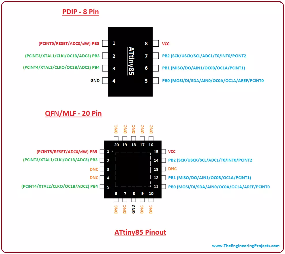
Introduction to Arduino Pro Mini

Hey Friends! Hope you are doing well. Today, I am going to give you a detailed Introduction to Arduino Pro Mini. It's a microcontroller board developed by Arduino.cc and is based on the Atmega328 microcontroller.

Arduino Pro Mini is quite similar to Arduino UNO in overall functionality however the main difference lies in its size and built-in programmer. Arduino Pro Mini is very small in size & it lacks a built-in programmer & USB Port. Arduino Uno comes with two onboard voltage regulators (i.e. 5V and 3.3V) while Arduino Pro Mini comes with a single voltage regulator.

There are two versions of Arduino Pro Mini available, first one operates at 5V & runs at 16MHz while the second one is of 3.3V runs at 8MHz.

Arduino boards are mainly used for the development of automation, robotics, embedded systems and other electronics projects. These boards were developed with the intention of providing easy hardware and software combination that gives a quick pathway to people with no technical background.

Arduino Pro Mini Key Features
No. Feature Value
1 Microcontroller ATmega328
2 Operating Frequency/Crystal Oscillator 16MHz/8MHz
3 Digital I/O Pins 14
4 Analog Pins 8
5 PWM(Pulse Width Modulation) Pins 6
6 Built-in Programmer Not available.
7 USB Port Not available.
8 Flash Memory 32KB
9 SRAM 2KB
10 EEPROM 1KB
11 Bootloader 0.5KB in Flash Memory.
In today's tutorial, I'll discuss each and everything related to Arduino Pro Mini so you don't need to scrape through the internet and find all information in one place. Let's get started.
Where To Buy?
No.ComponentsDistributorLink To Buy
1Arduino Pro MiniAmazonBuy Now

Introduction to Arduino Pro Mini

  • Arduino Pro Mini is a compact, small-sized & application-type microcontroller board, developed by Arduino.cc and comes with an Atmega328 microcontroller incorporated on the board.
  • This board comes with 14 Digital I/O Pins, out of which 6 pins are used for providing PWM output.
  • Arduino Pro Mini Pinout also consists of 8 Analog Pins.
  • The size of Arduino Pro Mini is 1/6th of the size of Arduino Uno, so it's quite small as compared to Arduino UNO.
  • Depending on operating voltage, Arduino Pro Mini is of two types:
    1. Operating Voltage: 5.0V, Crystal Oscillator: 16MHz, Voltage Regulator: KB33.
    2. Operating Voltage: 3.3V, Crystal Oscillator: 8MHz, Voltage Regulator: KB50.
  • In order to reduce the size, the USB port & built-in programmer are removed from Arduino Pro Mini, so after uploading code you can simply place it in your application(that's why also termed as application-type).
  • Official Arduino Software called Arduino IDE (Integrated development environment) is used to write & upload programming code. The code we write to program this board is normally called a sketch.
  • Arduino Pro Mini also has a Reset Button and a small LED connected to pin number 13.

Arduino Pro Mini Memory Allocations

  • Arduino Pro Mini comes with 3 types of built-in memories:
    1. Flash Memory of 32KB out of which 0.5KB is used by the bootloader code.
    2. SRAM of 2KB.
    3. EEPROM of 1KB.
Now let me give you a brief overview of these memories, I have explained them in detail here: What is a Microcontroller?
  • Flash Memory is a non-volatile memory and is used for storing the programming code. As it's a non-volatile memory so it stores information even if the connection with the power supply is lost.
  • SRAM(Static Random Access Memory) usually referred to as RAM memory is a volatile memory and is used to store temporary data i.e. variables. It loses data if we cut off the power supply.
  • EEPROM is a semi-volatile memory and thus can be erased by programming.

Arduino Pro Mini Specifications

Here, I have shared a few more specifications and functionalities of Arduino Pro Mini.
  • This board doesn't come with connectors already soldered which gives you the flexibility to solder the connectors in any way you want, based on the requirements and space available for your project.
  • There is only one voltage regulator incorporated on the board i.e 3.3V or 5V based on the version of the board.
  • The labeling on the voltage regulator defines the version of the board i.e. KB33 represents 3.3V edition and KB50 represents 5V edition. However, the board version can also be indicated by measuring the voltage between Vcc and GND pin.
  • Overcurrent protection is another feature available in Arduino Pro Mini.
  • The following figure shows the specifications of the board.

Arduino Pro Mini Datasheet

  • You can download Arduino Pro Mini Datasheet by clicking the below button:
Download Arduino Pro Mini Datasheet Now let's have a look at the Pinout of Arduino Pro Mini in detail:

Arduino Pro Mini Pinout

  • As we know, each pin of the Microcontroller is assigned with multiple functions.
  • In the below table, I have shared the key points of the Arduino Pro Mini pin diagram and labeled functions assigned to them:
Arduino Pro Mini Pinout
No. Pin Number Pin Description
1 Pins 0 - 13 14 Digital I/O Pins.
2 Pins A0 - A7 8 Analog Pins.
3 Pins 3, 5, 6, 9, 10 & 11 6 Pulse Width Modulation ( PWM ) Pins.
4 Pins 0(RX) & 1(TX) Serial Communication Pins.
5 Pins 10, 11, 12 & 13 SPI Communication Pins.
6 Pins A4 & A5 I2C Communication Pins.
7 Pin # 13 Built-In LED for Testing.
8 Pins 4 & 5 External Interrupt Pins.
  • Here's the Circuit Diagram of Arduino Pro Mini Pinout:

Arduino Pro Mini Power Pins

  • Vcc: Arduino Pro Mini Pinout consists of 2 Vcc Pins. It gives the regulated voltage i.e. 5V or 3.3V depending on the type of the board.
  • GND: There are 3 GND(ground) pins incorporated on the board.
  • RAW. This pin is used for supplying raw voltage to the board. You can power connect an external power supply ranging from 5V to 12 V.
  • Reset: Pro Mini board comes with 2 Reset Pins, which comes in handy if the board hangs up in the middle of the running program, making this pin LOW will reset the board.
  • In the below figure, I have highlighted the Power Pinout of Arduino Pro Mini:

Programming Header Pins

  • Programming Header: FTDI six-pin programmer is connected with these pins and is used to upload programming code on the Pro Mini board.

Arduino Pro Mini I/O Pins

  • Digital Pins: Arduino Pro Mini has 14 Digital I/O Pins in total labeled from 0 to 13, where Pin 0 is RX1 and Pin 1 is TX0.
  • Analog Pins: It has 8 analog pins labeled from A0 to A7. These pins are used to input analog signals and come with a total resolution of 10bit.
I have encircled digital pins with green color and analog pins with orange color in the below figure:

Arduino Pro Mini Communication Pins

  • Arduino Pro Mini supports 3 Communication Protocols for the transmission of data with other peripherals i.e. sensors, registers etc. and are named as:
    1. Serial Protocol.
    2. I2C Protocol.
    3. SPI(Serial Peripheral Interface) Protocol.
  • TXD & RXD Pins: These pins are used for serial communication. TXD represents the transmission of serial data while RXD is used for receiving the data. Code is also uploaded through Serial Protocol.
  • SPI Pins: Four pins 10(SS), 11(MOSI), 12(MISO), and 13(SCK) are used for communicating through SPI Protocol.
  • I2C Pins: Two Pins(A4 and A5) are used for developing I2C communication. A4 is known as serial data line (SDA) which holds the data and A5 shows serial clock line (SCL) which provides data synchronization clock.

Other Pinouts

  • PWM. There are 6 digital pins labeled as 3,5,6,9,10, and 11 available on the board that provide PWM (pulse width modulation).
  • External Interrupts. There are two external interrupts available called T0(at Pin 4) and T1(at Pin 5). They are also known as hardware interrupts.

Arduino Pro Mini Vs Other Arduino Boards

  • Most of the Arduino boards come with a USB port that is used to send the program from the computer to the board. However, in the case of Arduino Pro Mini, all of the USB circuitry is removed to make it as compact and small as possible. You can program the board using a USB to serial converter cable. The FT232RL USB serial module is very handy and preferable for programming this board. A six-pin FTDI header can be connected to a USB to serial converter that provides the USB power.
  • If you have already worked on the Arduino Uno board, then no need to buy a USB to serial converter cable as you can program the Pro Mini using Uno board. Make sure, the Pro Mini version you are working on comes with 5V regulation as it runs at 16MHz like Arduino Uno board. Programming your 3.3V Pro Mini board will not be compatible with the Arduino Uno board, hence making it very difficult to program the 3.3V version of the Pro Mini board.
  • The form factor is another major difference that makes this device unique.
  • Pro Mini comes in a very small and compact size which makes this device suitable for most applications. But small size comes with one limitation i.e. it doesn't compatible with Arduino Shields unless you hard-wire the board with Arduino Shield.

Arduino Pro Mini Set Up

  • First, you need to install the Arduino IDE software on your computer, which is the official software used to program Arduino boards.
  • Connect the board with USB to Serial converter (FTDI serial module) that is used to transfer the program from computer to the board.
  • Write the program in the IDE software in C language.
  • No separate burner is required to burn the code. You can directly burn the code in the IDE software and transfer it to the board.
  • Once you have burned and transferred the program to the board, the next step is to power the board to make it compatible with your project.
  • Apart from using FTDI serial module, there are two ways to power the board. You can power the board through the RAW by setting the voltage range anywhere between 5V to 12V. It will automatically regulate to 3.3V based on the version of the board. However, if your project comes with a regulated voltage of 3.3V, then you can connect it directly to the Vcc pin of the board. Make sure, the board version is KB33 that runs at 3.3V, another version KB50 will run at 5V.
  • These two ways of powering up the board are useful when you have disconnected the board with the computer and already burned the program using FTDI module.

Applications of Arduino Pro Mini

There are many applications of Arduino Boards, but the small size and ease of use make Arduino Pro Mini stand out from others, especially where space requirement of the project is highly concerned. That's all for today. We always strive to give you quality work based on your needs and requirements. However, if you are unsure or have any question, you can approach me in the comment section below. I'd love to help you according to best of my knowledge. Keep your suggestions coming; they help us provide you best content so you keep coming back for what we have to offer. Thanks for reading the article.

Introduction to Arduino Nano

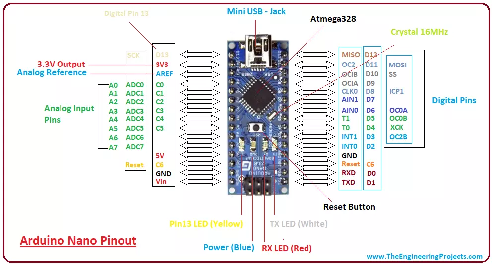
Hi Friends! I hope you are doing fine. Today, I am going to give you a detailed Introduction to Arduino Nano. We will also discuss Arduino Nano Pinout, datasheet, drivers & applications. It is a Microcontroller board developed by arduino.cc and based on Atmega328p / Atmega168.

Arduino boards are widely used in robotics, embedded systems, automation, Internet of Things(IoT) and electronics projects. These boards were initially introduced for students and non-technical users but nowadays Arduino boards are widely used in industrial projects.

Any kind of technical support and help is readily provided by the Arduino community. I have also designed this video tutorial on Arduino Nano:

  • Here's the figure showing the key points of Arduino Nano:
  • Here's the table showing important features of Arduino Nano:
No. Nano Features Value
1 Microcontroller Atmega328p
2 Crystal Oscillator 16MHz
3 Operating Voltage 5V
4 Input Voltage 6V-12V
5 Maximum Current Rating 40mA
6 USB Type-B Micro USB
7 ICSP Header Yes
8 DC Power Jack No
  • Here's the quick overview of Arduino Nano Pinout:
No. Pin Number Pin Description
1 D0 - D13 Digital Input / Output Pins.
2 A0 - A7 Analog Input / Output Pins.
3 Pin # 3, 5, 6, 9, 10, 11 Pulse Width Modulation ( PWM ) Pins.
4 Pin # 0 (RX) , Pin # 1 (TX) Serial Communication Pins.
5 Pin # 10, 11, 12, 13 SPI Communication Pins.
6 Pin # A4, A5 I2C Communication Pins.
7 Pin # 13 Built-In LED for Testing.
8 D2 & D3 External Interrupt Pins.
  • Arduino Nano offers three types of communications protocols, shown in the below table:
No. Communication Protocols Description
6 Serial Port 1 (Pin#0 is RX, Pin#1 is TX).
7 I2C Port 1 (Pin#A4 is SDA, Pin#A5 is SCL).
8 SPI Port 1 (Pin#10 is SS, Pin#11 is MOSI, Pin#12 is MISO, Pin#13 is SCK).
  • Here's the memory details present in Arduino Nano:
No. Memory Type Value
7 Flash Memory 32KB
8 SRAM Memory 2KB
7 EEPROM 1KB

Compare with other Arduino Boards:

Introduction to Arduino Nano

  • Arduino Nano is a small, complete, flexible and breadboard-friendly Microcontroller board, based on ATmega328p, developed by Arduino.cc in Italy in 2008 and contains 30 male I/O headers, configured in a DIP30 style.
  • Arduino Nano Pinout contains 14 digital pins, 8 analog Pins, 2 Reset Pins & 6 Power Pins.
  • It is programmed using Arduino IDE, which can be downloaded from the Arduino Official site.
  • Arduino Nano is simply a smaller version of Arduino UNO, thus both have almost the same functionalities.
  • It comes with an operating voltage of 5V, however, the input voltage can vary from 7 to 12V.
  • Arduino Nano's maximum current rating is 40mA, so the load attached to its pins shouldn't draw a current more than that.
  • Each of these Digital & Analog Pins is assigned with multiple functions but their main function is to be configured as Input/Output.
  • Arduino Pins are acted as Input Pins when they are interfaced with sensors, but if you are driving some load then we need to use them as an Output Pin.
  • Functions like pinMode() and digitalWrite() are used to control the operations of digital pins while analogRead() is used to control analog pins.
  • The analog pins come with a total resolution of 10-bits which measures the value from 0 to 5V.
  • Arduino Nano comes with a crystal oscillator of frequency 16 MHz. It is used to produce a clock of precise frequency using constant voltage.
  • There is one limitation of using Arduino Nano i.e. it doesn't come with a DC power jack, which means you can not supply an external power source through a battery.
  • This board doesn't use standard USB for connection with a computer, instead, it comes with Type-B Micro USB.
  • The tiny size and breadboard-friendly nature make this device an ideal choice for most applications where the size of the electronic components is of great concern.
  • Flash memory is 16KB or 32KB that all depends on the Atmega board i.e. Atmega168 comes with 16KB of flash memory while Atmega328 comes with a flash memory of 32KB. Flash memory is used for storing code. The 2KB of memory out of total flash memory is used for a bootloader.
  • The SRAM memory of 2KB is present in Arduino Nano.
  • Arduino Nano has an EEPROM memory of 1KB.
  • You can download Arduino Nano Datasheet by clicking the below button:
Download Arduino Nano Datasheet
  • The following figure shows the specifications of the Arduino Nano board.
  • It is programmed using Arduino IDE which is an Integrated Development Environment that runs both offline and online.
  • No prior arrangements are required to run the board. All you need is a board, a mini USB cable and Arduino IDE software installed on the computer.
  • USB cable is used to transfer the program from the computer to the board.
  • No separate burner is required to compile and burn the program as this board comes with a built-in boot-loader.

Now, let's have a look at Arduino Nano Pinout in detail:

Arduino Nano Pinout

  • The following figure shows the pinout of the Arduino Nano Board:
  • Each pin on the Nano board comes with a specific function associated with it.
  • We can see the analog pins that can be used as analog to digital converters, where A4 and A5 pins can also be used for I2C communication.
  • Similarly, there are 14 digital pins, out of which 6 pins are used for generating PWM.

Let's have a look at the Arduino Nano Pinout in detail:

Arduino Nano Power Pins

  • Vin: It is the input power supply voltage to the board when using an external power source of 7 to 12 V.
  • 5V: It is a regulated power supply voltage of the board that is used to power the controller and other components placed on the board.
  • 3V3: This is a minimum voltage generated by the voltage regulator on the nano board.
  • GND Pin: These are the ground pins on the board.
  • There are multiple ground pins on the board that can be interfaced accordingly when more than one ground pin is required.

Arduino Nano Function Pins

  • Reset Pin: Arduino Nano has 2 reset pins incorporated on the board, making any of these Reset pins LOW will reset the microcontroller.
  • Pin#13: A built-in LED is connected to pin#13 of the nano board.
  • This LED is used to check the board i.e. it's working fine or not.
  • AREF: This pin is used as a reference voltage for the input voltage.

Arduino Nano I/O Pins

  • Analog Pins: There are 8 analog pins on the board marked as A0 - A7.
  • These pins are used to measure the analog voltage ranging between 0 to 5V.
  • Digital Pins: Arduino Nano has 14 digital pins starting from D0 to D13.
  • These digital pins are used for interfacing third-party digital sensors and modules with Nano board.
  • PWM Pins: Arduino Nano has 6 PWM pins, which are Pin#3, 5, 6, 9, 10 and 11. (All are digital pins)
  • These pins are used to generate an 8-bit PWM (Pulse Width Modulation) signal.
  • External Interrupts: Pin#2 and 3 are used for generating external interrupts normally used in case of emergency, when we need to stop the main program and call important instructions.
  • The main program resumes once interrupt instruction is called and executed.

Nano Pinout for Communication Protocols

  • Serial Pins: These pins are used for serial communication where:
    1. Pin#0 is RX used for receiving serial data.
    2. Pin#1 is Tx used for transmitting serial data.
  • SPI Protocol: Four pins 10(SS->Slave Select), 11(MOSI -> Master Out Slave In), 12(MISO -> Master In Slave Out) and 13(SCK -> Serial Clock) are used for SPI (Serial Peripheral Interface) Protocol.
  • SPI is an interface bus and is mainly used to transfer data between microcontrollers and other peripherals like sensors, registers, and SD cards.
  • I2C Protocol: I2C communication is developed using A4 and A5 pins, where A4 represents the serial data line (SDA) which carries the data and A5 represents the serial clock line (SCL) which is a clock signal, generated by the master device, used for data synchronization between the devices on an I2C bus.

Arduino Nano Programming & Communication

  • The Nano board comes with the ability to set up communication with other controllers and computers.
  • The serial communication is carried out by the digital pins, Pin 0(Rx) and Pin 1(Tx) where Rx is used for receiving data and Tx is used for the transmission of data.
  • The serial monitor is added to the Arduino IDE, which is used to transmit textual data to or from the board.
  • FTDI drivers are also included in the software which behaves as a virtual com port to the software.
  • The Tx and Rx pins come with an LED which blinks as the data is transmitted between FTDI and USB connection to the computer.
  • Arduino Software Serial Library is used for carrying out serial communication between the board and the computer.
  • Apart from serial communication the Nano board also supports I2C and SPI communication. The Wire Library inside the Arduino Software is accessed to use the I2C bus.
  • The Arduino Nano is programmed by Arduino Software called IDE which is a common software used for almost all types of board available. Simply download the software and select the board you are using.
  • Uploading code to Arduino Nano is quite simple, as there's no need to use any external burner to compile and burn the program into the controller and you can also upload code by using ICSP (In-circuit serial programming header).
  • Arduino board software is equally compatible with Windows, Linux or MAC, however, Windows are preferred to use.

Arduino Uno Vs Arduino Nano

  • Both Arduino Uno and Arduino Nano come with the same functionality with little difference in terms of PCB layout, size and form factor.
  • Arduino Uno is a microcontroller board based on Atmega328 and comes with 14 digital I/O pins out of which 6 are PWM. There are 6 analog pins incorporated into the board. This board comes with everything required to support the microcontroller like a USB connection, a Power jack, a 16MHz oscillator, a reset button and an ICSP header. You don't require an extra peripheral with the board to make it work for automation.
  • It is a complete ready-to-use device that requires no prior technical skills to get hands-on experience with it. You can power it by using a DC power jack, battery or simply plug it into the computer using a USB cable to get started.
  • Arduino Nano is small and compact as compared to Arduino Uno. It lacks the DC power jack and comes with Mini USB support instead of regular USB. Also, the Nano board comes with two extra analog pins i.e. 8 pins as compared to 6 analog pins in the Uno board. Nano board is breadboard friendly while Uno board lacks this property.
  • However, both devices run at 5V, come with a current rating of 40mA and 16MHz of the clock frequency.

Applications of Arduino Nano

Arduino Nano is a very useful device that comes with a wide range of applications and covers less space as compared to other Arduino boards. Breadboard-friendly nature makes it stand out from other boards. The following are the main applications of Arduino Nano:
  • Engineering Students' Projects.
  • Medical Instruments
  • Industrial Automation
  • Android Applications
  • GSM Based Projects
  • Embedded Systems
  • Automation and Robotics
  • Home Automation and Defense Systems
  • Virtual Reality Applications

That's all for today. I hope you have got a clear idea about the Nano board. However, if still you feel skeptical or have any questions, you can approach me in the comment section below. I'd love to help you according to the best of my knowledge and expertise. Feel free to keep us updated with your valuable feedback and suggestions, they help us provide you quality work that resonates with your requirements and allows you to keep coming back for what we have to offer. Thanks for reading the article.

Introduction to Arduino Uno

Hi Friends! Hope you are doing great. Today, I am going to give you a detailed Introduction to Arduino Uno. It is a microcontroller board developed by Arduino.cc and is based on Atmega328 Microcontroller. The first Arduino project was started in Interaction Design Institute Ivrea in 2003 by David Cuartielles and Massimo Banzi with the intention of providing a cheap and flexible way for students and professionals to learn embedded programming.

Arduino UNO is a very valuable addition in electronics that consists of a USB interface, 14 digital I/O pins(of which 6 Pins are used for PWM), 6 analog pins and an Atmega328 microcontroller. It also supports 3 communication protocols named Serial, I2C and SPI protocol. You should also have a look at this video presentation on Arduino UNO:

  • Few main features of Arduino UNO are shown in the below figure:
Arduino UNO Features and Technical Specs
No. Parameter Name Parameter Value
1 Microcontroller Atmega328
2 Crystal Oscillator 16MHz
3 Operating Voltage 5V
4 Input Voltage 5-12V
5 Digital I/O Pins 14 (D0 to D13)
6 Analog I/O Pins 6 (A0 to A5)
7 PWM Pins 6 (Pin # 3, 5, 6, 9, 10 and 11)
8 Power Pins 5V, 3.3V, Vin, GND
9 Communication UART(1), SPI(1), I2C(1)
10 Flash Memory 32 KB (0.5KB is used by bootloader)
11 SRAM 2 KB
12 EEPROM 1 KB
13 ICSP Header Yes
14 Power sources DC Power Jack & USB Port

I'll try to cover each and everything related to Arduino Uno, so you get a clear idea of what it does, its main features, working and everything you need to know. Let's get started.

Where To Buy?
No.ComponentsDistributorLink To Buy
1Arduino UnoAmazonBuy Now

Introduction to Arduino Uno

  • Arduino Uno is a microcontroller board, developed by Arduino.cc, based on the Atmega328 microcontroller and is marked as the first Arduino board developed(UNO means "one" in Italian).
  • The software used for writing, compiling & uploading code to Arduino boards is called Arduino IDE (Integrated Development Environment), which is free to download from Arduino Official Site.
  • It has an operating voltage of 5V while the input voltage may vary from 7V to 12V.
  • Arduino UNO has a maximum current rating of 40mA, so the load shouldn't exceed this current rating or you may harm the board.
  • It comes with a crystal oscillator of 16MHz, which is its operating frequency.
  • Arduino Uno Pinout consists of 14 digital pins starting from D0 to D13.
  • It also has 6 analog pins starting from A0 to A5.
  • It also has 1 Reset Pin, which is used to reset the board programmatically. In order to reset the board, we need to make this pin LOW.
  • It also has 6 Power Pins, which provide different voltage levels.
  • Out of 14  digital pins, 6 pins are used for generating PWM pulses of 8-Bit resolution. PWM pins in Arduino UNO are D3, D5, D6, D9, D10 and D11.
  • Arduino UNO comes with 3 types of memories associated with it, named:
    • Flash Memory: 32KB
    • SRAM: 2KB
    • EEPROM: 1KB
  • Arduino UNO supports 3 types of communication protocols, used for interfacing with third-party peripherals, named:
    • Serial Protocol
    • I2C Protocol
    • SPI Protocol
  • You can download the Arduino UNO datasheet by clicking the below button:
Download Arduino UNO Datasheet
  • Apart from USB, a battery or AC to DC adopter can also be used to power the board.

Features of Arduino Uno Board

  • Arduino Uno comes with a USB interface i.e. USB port is added on the board to develop serial communication with the computer.
  • Atmega328 microcontroller is placed on the board that comes with a number of features like timers, counters, interrupts, PWM, CPU, I/O pins and based on a 16MHz clock that helps in producing more frequency and number of instructions per cycle.
  • It is an open-source platform where anyone can modify and optimize the board based on the number of instructions and tasks they want to achieve.
  • This board comes with a built-in regulation feature that keeps the voltage under control when the device is connected to the external device.
  • A reset pin is present in the board that resets the whole board and takes the running program in the initial stage. This pin is useful when the board hangs up in the middle of the running program; pushing this pin will clear everything up in the program and starts the program right from the beginning.
  • There are 14 I/O digital and 6 analog pins incorporated in the board that allows the external connection with any circuit with the board. These pins provide flexibility and ease of use to the external devices that can be connected through these pins. There is no hard and fast interface required to connect the devices to the board. Simply plug the external device into the pins of the board that are laid out on the board in the form of the header.
  • The 6 analog pins are marked as A0 to A5 and come with a resolution of 10bits. These pins measure from 0 to 5V, however, they can be configured to the high range using analogReference() function and AREF pin.
  • Only 5 V is required to turn the board on, which can be achieved directly using a USB port or external adopter, however, it can support an external power source up to 12 V which can be regulated and limit to 5 V or 3.3 V based on the requirement of the project.

Arduino Uno Pinout

Arduino Uno is based on an AVR microcontroller called Atmega328. This controller comes with 2KB SRAM, 32KB of flash memory, 1KB of EEPROM. Arduino Board comes with 14 digital pins and 6 analog pins. ON-chip ADC is used to sample these pins. A 16 MHz frequency crystal oscillator is equipped on the board. The following figure shows the pinout of the Arduino Uno Board.

Arduino UNO Pin Description

There are several I/O digital and analog pins placed on the board which operates at 5V. These pins come with standard operating ratings ranging between 20mA to 40mA. Internal pull-up resistors are used in the board that limits the current exceeding the given operating conditions. However, too much increase in current makes these resisters useless and damages the device.
  • LED. Arduino Uno comes with a built-in LED which is connected through pin 13. Providing HIGH value to the pin will turn it ON and LOW will turn it OFF.
  • Vin. It is the input voltage provided to the Arduino Board. It is different than 5 V supplied through a USB port. This pin is used to supply voltage. If a voltage is provided through a power jack, it can be accessed through this pin.
  • 5V. This board comes with the ability to provide voltage regulation. 5V pin is used to provide output regulated voltage. The board is powered up using three ways i.e. USB, Vin pin of the board or DC power jack.
  • USB supports voltage around 5V while Vin and Power Jack support a voltage ranges between 7V to 20V. It is recommended to operate the board on 5V. It is important to note that, if a voltage is supplied through 5V or 3.3V pins, they result in bypassing the voltage regulator that can damage the board if the voltage surpasses its limit.
  • GND. These are ground pins. More than one ground pins are provided on the board which can be used as per requirement.
  • Reset. This pin is incorporated on the board which resets the program running on the board. Instead of physical reset on the board, IDE comes with a feature of resetting the board through programming.
  • IOREF. This pin is very useful for providing voltage reference to the board. A shield is used to read the voltage across this pin which then selects the proper power source.
  • PWM. PWM is provided by 3,5,6,9,10, 11pins. These pins are configured to provided 8-bit output PWM.
  • SPI. It is known as Serial Peripheral Interface. Four pins 10(SS), 11(MOSI), 12(MISO), 13(SCK) provide SPI communication with the help of the SPI library.
  • AREF. It is called Analog Reference. This pin is used for providing a reference voltage to the analog inputs.
  • TWI. It is called Two-wire Interface. TWI communication is accessed through Wire Library. A4 and A5 pins are used for this purpose.
  • Serial Communication. Serial communication is carried out through two pins called Pin 0 (Rx) and Pin 1 (Tx).
  • Rx pin is used to receive data while Tx pin is used to transmit data.
  • External Interrupts. Pin 2 and 3 are used for providing external interrupts. An interrupt is called by providing LOW or changing value.

Communication and Programming

Arduino Uno comes with the ability of interfacing with other Arduino boards, microcontrollers and computers. The Atmega328 placed on the board provides serial communication using pins like Rx and Tx. The Atmega16U2 incorporated on the board provides a pathway for serial communication using USB com drivers. A serial monitor is provided on the IDE software which is used to send or receive text data from the board. If LEDs placed on the Rx and Tx pins will flash, they indicate the transmission of data. Arduino Uno is programmed using Arduino Software which is a cross-platform application called IDE written in Java. The AVR microcontroller Atmega328 laid out on the base comes with built-in bootloader that sets you free from using a separate burner to upload the program on the board.

Applications of Arduino UNO

Arduino Uno comes with a wide range of applications. A larger number of people are using Arduino boards for developing sensors and instruments that are used in scientific research. Following are some main applications of the board.
  • Embedded System
  • Security and Defense System
  • Digital Electronics and Robotics
  • Parking Lot Counter
  • Weighing Machines
  • Traffic Light Count Down Timer
  • Medical Instrument
  • Emergency Light for Railways
  • Home Automation
  • Industrial Automation
There are a lot of other microcontrollers available in the market that are more powerful and cheap as compared to the Arduino board. So, why you prefer Arduino Uno? Actually, Arduino comes with a big community that is developing and sharing knowledge with a wide range of audiences. Quick support is available pertaining to the technical aspects of any electronic project. When you decide Arduino board over other controllers, you don't need to arrange extra peripherals and devices as most of the functions are readily available on the board that makes your project economical in nature and free from a lot of technical expertise. That's all for today. I hope you have got a lot of information regarding the Arduino Uno board. However, if you are unsure or have any questions you can approach me in the comment section below. I'd love to help you according to the best of my knowledge. Keep your feedback and suggestions coming; they help us provide you quality work that resonates with your needs and requirements. Thanks for reading the article.

Introduction to Atmega16

Hey Fellas! Hope you are doing fine. Microcontrollers play an important role in the development of embedded systems. They are used where automation is an integral part of the system. Today, I am going to unlock the details on the Introduction to Atmega16.  It is a 40-pin low power 8-bit microcontroller which is developed using CMOS technology and based on AVR architecture. This is the most commonly used AVR microcontroller which belongs to Atmel Mega family. You must have a look at microcontroller called Atmega328 that also belongs to the mega family. Other microcontrollers that are readily available and fall under AVR category are Atmega 8 and Atmega 32. All these controllers perform similar tasks, however, they are only different in terms of their memory size and cost. I'll discuss each and everything related to this controller so you don't need to scrape through the internet and find all information in one place. Let's dive in and explore what is this about, its main features, pin diagram and everything you need to know.

Introduction to Atmega16

  • Atmega16 is a 40-pin low power microcontroller which is developed using CMOS technology.
  • CMOS is an advanced technology which is mainly used for developing integrated circuits. It comes with low power consumption and high noise immunity.
  • Atmega16 is an 8-bit controller based on AVR advanced RISC (Reduced Instruction Set Computing) architecture. AVR is family of microcontrollers developed by Atmel in 1996.
  • It is a single chip computer that comes with CPU, ROM, RAM, EEPROM, Timers, Counters, ADC and four 8-bit ports called PORTA, PORTB, PORTC, PORTD where each port consists of 8 I/O pins.
  • Atmega16 has built-in registers that are used to make a connection between CPU and external peripherals devices. CPU has no direct connection with external devices. It can take input by reading registers and give output by writing registers.
  • Atmega16 comes with two 8-bit timers and one 16-bit timer. All these timers can be used as counters when they are optimized to count the external signal.
  • Most of the necessary peripherals required to run automatic functions are incorporated in this device like ADC (analog to digital converter), Analog comparator, USART, SPI, which make it economical as compared to a microprocessor that requires external peripheral to perform various functions.
  • Atmega16 comes with 1KB of static RAM which is a volatile memory i.e stores information for short period of time and highly depends on the constant power supply. Whereas 16KB of flash memory, also known as ROM, is also incorporated in the device which is non-volatile in nature and can store information for long period of time and doesn't lose any information when the power supply is disconnected.
  • Atmega16 works on a maximum frequency of 16MHz where instructions are executed in one machine cycle.

Architecture of Atmega16

Following figure shows the architecture of Atmega16 that is based on Harvard Architecture and comes with separate buses and memories. Instructions are stored in the program memory.
1. CPU
CPU is like a brain of the controller which helps in executing a number of instructions. It can handle interrupts, perform calculations and control peripherals with the help of registers. Atmega16 comes with two buses called instruction bus and data bus. The CPU reads the instructions in the instruction bus while data bus is used to read or write the corresponding data. The CPU mainly consists of the program counter, general purpose registers, stack pointer, instruction register and an instruction decoder.
2. ROM
The controller program is stored in ROM, also known as non-volatile programmable flash memory. The flash memory comes with a resolution of at least 10,000 write/erase cycles. Flash memory is mainly divided into two parts known as Application flash section and booth flash section. Program of the controller is stored in the applications flash section. While booth flash section is optimized to work directly when the controller is powered up.
3. RAM
The SRAM (static random access memory) is used for storing information temporarily and comes with 8-bit registers. This is just like a regular computer RAM which is used to supply data through the runtime.
4. EEPROM
The EEPROM (Electronically Erasable Read Only Memory) is non-volatile memory used as a long time storage. It has no involvement in executing the main program. It is used for storing the configuration of the system and device parameters which continues to work in the reset of the application processor. EEPROM comes with a limited write cycle up to 100,000 while read cycles are unlimited. While using EEPROM, write minimum instructions as per requirement, so you can get benefit from this memory for a longer time.
5. Interrupt
The interrupt is used for an emergency which puts the main function on hold and executes the necessary instructions at that time. Once the interrupt is called and executed the code switches back to the main program.
6. Analog and Digital I/O Modules
Digital I/O modules are used to set a digital communication between the controller and external devices. While analog I/O modules are used for transferring analog information. Analog comparators and ADC fall under the category of analog I/O modules.
7. Timer/Counter
Timers are used for calculating the internal signal within the controller. Atmega16 comes with two 8-bit timers and one 16-bit timer. All these timers work as a counter when they are optimized for external signals.
8. Watchdog Timer
The watchdog timer is a remarkable addition in this controller which is used to generate the interrupt and reset the timer. It comes with 128kHz distinct CLK source.
9. Serial Communication
Atmega16 comes with USART and SPI units that are used for developing serial communication with the external devices.

Atmega16 Pinout

Following figure shows the pin diagram of this AVR microcontroller Atmega16.
  • Atmega16 is preferred over other microcontrollers like Atmel 8051 because it comes with much faster ability to execute instructions and consist of modified RISC processor.
  • It has a built-in flash which comes with features of a bootloader. It has built-in 10-bit ADC, SPI, PWM, and EEPROM.
Pin Description of Atmega16
Atmega16 comes with 40 pins where each pin is used to perform a specific task. There are total 32 I/O pins and four ports. Each port consists of 8 I/O pins.
  • PORTA = 8 Pins ( Pin 33 - 40 )
  • PORTB = 8 Pins ( Pin 1 - 8 )
  • PORTC = 8 Pins ( Pin 22 - 29 )
  • PORTD = 8 Pins ( Pin 14 - 21 )
Following are the main functions associated with pins. PORTA. Pins from 33 to 40 fall under PORTA. It acts like analog inputs to A/D converter. However, in the absence of A/D converter, PORTA is used as an 8-bit bidirectional I/O port. It comes with internal pull-up resistors. PORTB. Pins from 1 to 8 belong to PORTB. These are I/O bidirectional pins. This port also consists of internal pull-up resistors. PORTC. PORTC is an I/O bidirectional port that consists of 8 pins. Pin from 22 to 29 belongs to this port.  Similar to other ports, it  comes with internal pull-up resistors. PORTD. Pin from 14 to 21 belongs to this port. It is a bidirectional port where each pin can be used as input or output pin. However, there are additional features associated with this port like interrupts, serial communication, timer, and PWM. Reset. Pin9 is an active low reset Pin. A low-level pulse for longer than minimum pulse length will produce a reset. Short pulses are unlikely to produce reset. VCC. Pin10 is a power supply pin for this controller. The power supply of 5 V is required to put this controller in a running condition. GND. Pin11 is a ground pin. AREF. Pin32 is an analog reference pin mainly used for A/D converter. AVCC. Pin30 is an AVCC which is a supply voltage pin for PORTA and ADC. It is connected to VCC through a low pass filter in the presence of ADC. However, in the absence of ADC, AVCC is externally connected to VCC. Pin 12 & 13. A crystal oscillator is connected with these pins. Atmega16 works at the internal frequency of 1MHZ; the oscillator is added to generate high clock pulses and frequency.
Applications
AVR controllers come with a wide range of applications where automation is required. Following are the main applications of Atmega16.
  • Medical equipment
  • Home automation
  • Embedded systems
  • Arduino Projects
  • Used in automobiles and industrial automation
  • Home appliances and security systems
  • Temperature and pressure control devices
That's all for today. I hope you have got enough information regarding Atmega16. If you are unsure or have any question, you can approach me in the comment section below. I'd love to help you in any way I can. Feel free to keep us updated with your valuable suggestions and feedback. They help us provide you quality content. Thanks for reading the article.

Smoke Detector with Arduino & MQ2 Sensor

Hello everyone, I hope you all are  doing great. In today's tutorial, we are gonna have a look at How to design a Smoke Detector with Arduino. Its quite a simple project but if you are working on any security project then you must add this feature in it. You should also download this Gas Sensor Library for Proteus, and design its simulation. I will use gas sensor MQ2 for this project. I have purchased MQ2 Gas Sensor module as its quite easy to interface with Arduino. Arduino board I'm using is Arduino UNO. I have also designed an LPG Gas Leak Detect using Arduino using this MQ2 Sensor. So, let's get started with How to design Smoke Detector with Arduino & MQ2 Sensor.

Smoke Detector with Arduino & MQ2 Sensor

  • First of all, we need to connect some jumper wires between Arduino and MQ2 smoke sensor shield.
  • Here's the image of our Gas sensor and you can see, it has four pins in total.
  • This gas sensor has four pins in total, which are:
    • Vcc: We need to provide +5V.
    • GND: We need to ground it.
    • D0: Digital Output.
    • A0: Analog Output.
  • So now you will need four male to female jumper wires and connect them as shown in below figure:
  • Sensor's pins are labelled on the back side and I have connected these four pins as follows:
    • White Wire: Vcc of Sensor connected with +5V of Arduino.
    • Black Wire: GND of Sensor connected with GND of Arduino.
    • Grey Wire: D0 of Sensor connected with Pin # 8 of Arduino.
    • Orange Wire: A0 of Sensor connected with A0 of Arduino.
  • So, now let's design our code in Arduino software in which we will detect whether there's smoke around or not.
  • I'm gonna use the analog output of our sensor and will first display the analog value in my Serial Monitor.
  • I have used the below code, so copy it and upload in your Arduino board:
int Input = A0;
int SensorVal = 0;

void setup() {
  Serial.begin(9600);
  pinMode(Input, INPUT);
  Serial.println("Interfacing of Smoke Sensor with Arduino");
  Serial. println("Design by www.TheEngineeringProjects.com");
  Serial.println();
}

void loop() {

  SensorVal = analogRead(Input);
  Serial.println(SensorVal);
  delay(500);
}
  • Now open the Serial Monitor of Arduino to check the analog values coming from our sensor.
  • If everything goes fine then you will get something like this in your Serial Monitor:
  • You can see we are getting the values in range of 420 to 450.
  • You should read How to do Arduino Serial Communication, if you don't know how to get data serially.
  • Now let's place a burning cigarette near it for smoke. (Cigarettes are injurious to health :P )
  • When the sensor will sense smoke in its surroundings then its value will start to increase and in my case it reached to around 650.
  • So, let's place a check in our Arduino coding to detect whether there's smoke or not.
  • So add below code in your Arduino software and upload it to your Arduino board.
int Input = A0;
int SensorVal = 0;

int Check = 0;

void setup() {
  Serial.begin(9600);
  pinMode(Input, INPUT);
  Serial.println("Interfacing of Smoke Sensor with Arduino");
  Serial. println("Design by www.TheEngineeringProjects.com");
  Serial.println();
}

void loop() {

  SensorVal = analogRead(Input);
  if((SensorVal > 500) && (Check == 1))
  {
    Serial.println("Smoke Detected . . .");
    Check = 0;
  }

  if((SensorVal < 500) && (Check == 0))
  {
    Serial.println("All Clear . . .");
    Check = 1;
  }
  //Serial.println(SensorVal);
  delay(500);
}
  • After uploading the code to Arduino, open your Serial Monitor.
  • If everything goes fine then you will get something as shown in below figure:
  • Now let me bring the cigarette close to get some smoke. (Cigarettes are injurious to health :P )
  • You will get the warning as soon as it will detect smoke as shown in below figure:
  • We got the detection of smoke in our Serial Terminal.
So, that's how we can easily design a Smoke Detector with Arduino & MQ2 Sensor. I think now you can quite easily design this smoke detector project at home. I hope you will enjoy it. Will meet you guys in next tutorial. Till then take care and have fun !!! :)

Heart Beat Monitor using Arduino in Proteus

Hello friends, I hope you all are doing great and having fun in your lives. In today's tutorial, we are gonna design a Heart Beat Monitor using Arduino in Proteus ISIS. You should download this Heart Beat Sensor Library V2.0 for Proteus because we are gonna use that to detect heart beat in Proteus. I have also used a 20x4 LCD which will display our heart rate value. You should download this New LCD Library for Proteus. I have counted the heart beat for ten seconds and then I have multiplied it with 6 to get the heartbeat per minute which is abbreviated as bpm (beats per minute). So, let's get started with Heart Beat Monitor using Arduino in Proteus ISIS.
Where To Buy?
No.ComponentsDistributorLink To Buy
1LCD 20x4AmazonBuy Now
2Arduino UnoAmazonBuy Now

Heart Beat Monitor using Arduino in Proteus

  • First of all, click the below button to download this complete Proteus simulation & Arduino code for Heart Beat Monitor:
Heart Beat Monitor using Arduino in Proteus

Proteus Simulation of Heart Rate Monitor

  • Now let's have a look at How we have designed this simulation and How it works.
  • So, design a simple circuit in Proteus as shown in the below figure:
  • As you can see in the above figure, we have our Arduino UNO board along with LCD and Heart Beat Sensor.
  • There's also a Button attached to Pin # 2, so when we press this button our Arduino will start counting the Heart Beat and will update it on the LCD.
Now let's have a look at the programming code for Heart Rate Monitor:

Arduino Code for Heart Rate Monitor

  • Here's the code which I have used for this Heart Beat Monitor using Arduino:
#include <LiquidCrystal.h>
#include <TimerOne.h>
LiquidCrystal lcd(13, 12, 11, 10, 9, 8);

int HBSensor = 4;
int HBCount = 0;
int HBCheck = 0;
int TimeinSec = 0;
int HBperMin = 0;
int HBStart = 2;
int HBStartCheck = 0;

void setup() {
  // put your setup code here, to run once:
  lcd.begin(20, 4);
  pinMode(HBSensor, INPUT);
  pinMode(HBStart, INPUT_PULLUP);
  Timer1.initialize(800000); 
  Timer1.attachInterrupt( timerIsr );
  lcd.clear();
  lcd.setCursor(0,0);
  lcd.print("Current HB  : ");
  lcd.setCursor(0,1);
  lcd.print("Time in Sec : ");
  lcd.setCursor(0,2);
  lcd.print("HB per Min  : 0.0");
}

void loop() {
  if(digitalRead(HBStart) == LOW){lcd.setCursor(0,3);lcd.print("HB Counting ..");HBStartCheck = 1;}
  if(HBStartCheck == 1)
  {
      if((digitalRead(HBSensor) == HIGH) && (HBCheck == 0))
      {
        HBCount = HBCount + 1;
        HBCheck = 1;
        lcd.setCursor(14,0);
        lcd.print(HBCount);
        lcd.print(" ");
      }
      if((digitalRead(HBSensor) == LOW) && (HBCheck == 1))
      {
        HBCheck = 0;   
      }
      if(TimeinSec == 10)
      {
          HBperMin = HBCount * 6;
          HBStartCheck = 0;
          lcd.setCursor(14,2);
          lcd.print(HBperMin);
          lcd.print(" ");
          lcd.setCursor(0,3);
          lcd.print("Press Button again.");
          HBCount = 0;
          TimeinSec = 0;      
      }
  }
}

void timerIsr()
{
  if(HBStartCheck == 1)
  {
      TimeinSec = TimeinSec + 1;
      lcd.setCursor(14,1);
      lcd.print(TimeinSec);
      lcd.print(" ");
  }
}
  • In this code, I have used a TimerOne Library which creates an interrupt after every 1sec.
  • On each interrupt, it executes timerIsr() function, in which I have placed a check that whenever this interrupt will call we will increment TimeinSec variable.
  • So, when TimeinSec will become equal to 10 then I am simply multiplying it with 6 and updating it on the LCD.
  • So, use the above code and get your Hex File from Arduino Software and update it in your Proteus Simulation.

Simulating Heart Rate Monitor

  • Now run your Proteus Simulation and you will get something as shown in the below figure:
  • Now click this HB button and it will start counting the HB as well as will count the Time in seconds.
  • After ten seconds it will multiply the current heart rate with six and will give the Heart Beat Per Minute.
  • Here's a final image of the result:
  • You can change the value of Heart Beat from the variable resistor connected with Heart Beat Sensor.
  • Let's change the value of variable resistance connected to Heart Beat sensor, and have a look at the results.
  • You have to press the button again in order to get the value.
  • Here's the screenshot of the results obtained:
  • So, now the heart is beating a little faster and we have got 108 bpm.
  • If you run this simulation then you will notice that the second is quite slow which I think is because of Proteus.
  • I have tested this code on hardware and it worked perfectly fine, although you need to change heart beat sensor's values in coding.
  • Here's the video in which I have explained the working of this Heart Rate Monitor Simulation in detail.
So, that was all about Heart Beat Monitor using Arduino in Proteus ISIS. I hope you have enjoyed it and will get something out of it. Have a good day. :)

Real Time Security Control System using XBee and GSM

Hello everyone, I hope you all are doing great. In today's post, I am going to share a Final Year Project in detail, named as Real Time Security Control System using XBee and GSM. I will give you all the details so that you can easily design it on your own. I've given the Proteus Simulation to download below. In that zip file, you will get both the Arduino codes and Proteus Simulations.

I have divided this whole project design into four parts. If you got into any trouble in your project, then ask in comments and I will try my best to resolve them. So, today we are gonna have a look at the basics of this Security project. There are a lot of systems introduced in the market these days that are used to transfer sensor data from one node to another either wirelessly or through some wired connection. The proposed technique also works on this same principle. But a lot of modifications are intended to introduce in order to enhance this technique.

Where To Buy?
No.ComponentsDistributorLink To Buy
1LCD 20x4AmazonBuy Now
2NEO-6MAmazonBuy Now
3SIM900AmazonBuy Now
4DS18B20AmazonBuy Now
5Flame SensorsAmazonBuy Now
6MQ-2AmazonBuy Now
7Arduino UnoAmazonBuy Now

Real Time Security Control System

  • You can download this Project by clicking the below button:
Real Time Security Control System using XBee and GSM Now let's have a look at the project description:

Project Description

In this project, I have designed a real-time security system, which consists of two wireless nodes named as
  • Sensor Node
  • Base Node.
So, first of all, let's have a look at these two nodes one by one. First, I am going to discuss Sensor Node:

Sensor Node

The sensor node is placed in that building which is needed to be secured. Sensor node consists of three different sensors and two modules used for security purposes named as:
  • Sensors:
    • Smoke Sensor: To detect Smoke.
    • Flame Sensor: Used for Fire Detection.
    • Temperature Sensor: Measuring Temperature of surroundings.
  • Modules:
    • GSM module: is used to deliver the notification message if any fault occurs in the system.
    • GPS module: is used to locate the exact position of the fault that occurred.
Below two modules are used for controlling purposes:
  • Modules:
    • Arduino UNO: All these Sensors and modules are connected to Arduino UNO.
    • XBee Module: To send sensors' data & GPS Location to Base Node.
Block Diagram for the Sensor Unit of Real Time Security Control System using XBee and GSM is shown in below figure: Now let's have a look at the Base Unit of Real Time Security Control System using XBee and GSM.
Base Unit:
  • The base node will be placed in the Control Department. It could be your security guard's room or the nearby police station.
  • This node will receive the data from the sensor node via XBee module.
  • So, in total it will have three modules on it which are:
    • XBee Module: It is used to maintain wireless communication between the sensor node and base node.
    • LCD 20x4: It is used to display real-time conditions like sensors' values & GPS Location.
    • Arduino Mega 2560: It is used to control both of these modules.
  • Here's the block diagram of Base Unit for Real Time Security Control System using XBee and GSM:

Components Selected

In the previous section, we have had a look at the basic Introduction of our Real Time Security Control System using XBee and GSM. This section will elaborate on the selection of the components which is the most important factor before designing any project/product. This is basically a simulation based project so there is no hardware involved in this project. The proposed technique is designed in Proteus ISIS. All of the components are taken from the Proteus library.

Flame Sensor

  • The flame sensor is an electronic device usually used for fire detection purposes.
  • It can be used in homes, industries, offices, schools etc.
  • A certain threshold is adjusted while designing the algorithm.
  • When the fire flames cross that particular threshold, the flame sensor will send a signal to Arduino which will send that signal through Xbee to Base Unit immediately.
  • As soon as the signal will be received on the Base Unit, the alarm will turn ON and hence guards will come to know that this area has become dangerous now.
  • Immediate precautions must be taken in this case.
  • Flame Sensor is not available in Proteus so we have designed its library.
  • You should download this Flame Sensor Library for Proteus.

Smoke Sensor

  • A smoke sensor is used to detect a certain level of smoke within the desired region.
  • It is usually used in homes and organizations for the detection of fire or internal burns.
  • It is a low-cost and very sensitive sensor that also beeps if someone is smoking in its coverage area.
  • This Smoke Sensor will detect any smoke in the area then it will warn the Arduino board which will, in turn, send a signal via XBee to Base Unit.
  • Proteus software doesn't have a smoke sensor in it so you should download this Smoke Sensor Library for Proteus.

Temperature Sensor

  • The temperature sensor is an electronic sensor used to estimate the temperature in the surroundings.
  • The temperature range can be adjusted while designing its algorithm.
  • When the temperature in the surroundings reaches the adjusted threshold, it generates a notification.
  • Most of the time an alarm is attached to the temperature sensor. The alarm starts to beep when the desired temperature is reached. It can be used in homes, offices and organizations to maintain the temperature of a certain area according to the desired requirements.
  • But in our project we want to send a signal to the base unit, so that's why this sensor will send a signal to the base unit.

XBee Module

  • XBee is selected as a wireless module. The proposed technique consists of two XBee modules.
  • One is attached to the base unit and the other is attached to the sensor unit.
  • The data is transmitted by the sensor unit via XBee module.
  • And the XBee module attached to the base unit receives that data from the sensor unit and sends it to the microcontroller to manipulate it.
  • There are many wireless modules available in the market these days e.g. Radio Frequency (RF) module.
  • Some of them are not used commonly due to their shorter ranges e.g. Bluetooth module.
  • XBee module is far better as compared to the Bluetooth module and provides a larger coverage area in comparison to similar wireless modules.
  • So, XBee is used in this project. XBee module is not available in Proteus so that's why you should download XBee Library for Proteus.

Arduino UNO

  • The microcontroller plays a vital role in any project and is like a backbone of a particular project.
  • Arduino UNO and Mega 2560 both are selected as a microcontroller.
  • Arduino UNO is attached to the sensor unit and Arduino Mega 2560 is attached to the base unit.
  • Arduino is an open-source device. Students can take online help in almost every task. Online source codes are also available for different tasks.
  • So, a student can easily perform them with a proper understanding.
  • Arduino boards are also not available in Proteus so you should download this Arduino Library for Proteus.

GPS Module

  • GPS module is used to locate the exact location of the fault.
  • GPS module will be attached to Sensor Unit, so if anything goes wrong then we can also get the GPS location via SMS.
  • It will provide us the longitude and latitude of the fault that occurred on the sensor unit.
  • So, now if any of these sensors goes wrong then you can easily get the location of your sensor node via SMS.
  • Proteus doesn't have GPS Module in it so you should download this GPS Library for Proteus.

GSM Module

  • GSM module is used for security purposes.
  • If a fault occurs at any position within the network, a notification message will be generated and sent towards the base unit from the sensor unit.
  • We can also generate a call using this GSM which will be a much better way.
  • This GSM module will also send the location via SMS. We have received this location from GPS in the form of longitude and latitude.
  • Proteus doesn't have GSM Module in it so you should download this GSM Library for Proteus.
So, these are all the components/modules, which I have used in this project. So, in the first part, have seen the basic Introduction of the project and then in the second section, we have had a detailed overview of all the modules used. So, now in the next section which is the third part I am gonna show you How to design these Proteus Simulations.

Proteus Simulation of Security Control System

In this section, we are gonna have a look at how to design these Proteus Simulations for Real Time Security Control System using XBee and GSM. As you know, I have used Arduino so we also need to discuss the code in order to run these simulations. So, first, we will design the proteus simulations and then we will write its code.

Proteus Simulations

  • I have designed two simulations for this project.
  • First of all, what you need to do is to download all those above Proteus Libraries and add them properly.
  • I have given detailed instructions in each post about How to use them.
  • After adding all these Libraries, now restart your Proteus software and design a circuit for the Sensor Unit.
  • Proteus Simulation of Sensor Unit is shown in the below figure:
  • As you can see in the above figure, the Sensor unit consists of three different sensor modules, which are:
    • Temperature sensor.
    • Smoke sensor.
    • Flame sensor.
  • In this unit, Arduino UNO is used as a microcontroller to get data from all the sensors and this data will be transmitted wirelessly towards the base unit for proper monitoring.
  • XBee module is used for wireless communication between the sensor unit and the base unit.
  • GPS module is interfaced in order to locate the exact position of the fault that occurred in the system.
  • Now we are gonna design our second simulation for the Base Unit.
  • The Proteus Simulation of Base Unit is shown in the below figure:
  • The base unit is basically a monitoring end of the system.
  • All the data obtained from the sensors is transmitted by the sensor unit towards the base unit.
  • The base unit has an Arduino Mega 2560 as a micro-processing unit.
  • Just like the sensor unit, an XBee module is also attached to the base unit in order to receive the data wirelessly sent by the base unit.
  • There is an LCD on the base unit. It is used to visualize the obtained results. It displays different messages e.g. fault detection, sensors data etc.
  • GSM module is used in the base unit to send the notification if a fault occurs in the system or the system is showing some abnormal behavior even for an instance.
  • This GSM module will also send the location in SMS. You have to enter the number of recipients in the programming code.

Arduino Code of Security Control System

  • When you download this project, you will get a .rar file and within that file, you will find two folders.
  • One of them will have the Arduino Codes and the other one will have Proteus Simulations.
  • I have already added all the hex files so you just need to run these simulations.
  • If you got into any trouble then use our Contact Form and our team will help you out.
  • You should also need to read How to Get the hex file from your Arduino Software.

Proteus Simulation Results

  • Now coming towards the last section of this project, now I am gonna show you the results of these simulations.
  • So, I have run both of these Simulations and here's the first look at Base Unit:
  • The LCD on the base unit is displaying the title of our project.
  • Virtual Terminal is connected with Arduino so that we could also have a look at incoming or outgoing data.
  • After that first of all, Arduino will communicate with the GSM module and will set its settings, as shown in the below figure:
  • Now our GSM module has configured, so the next screen of the base unit is shown below:
  • As you can see in the above figure that LCD is displaying the values of all three sensors and because all are normal that's why the Alarm is OFF.
  • The temp value is 0 because we haven't yet received the data from the sensor unit.
  • Now let's run our Sensor Unit and make our Fire Sensor HIGH, then you will get results as shown in the below figure:
  • The alarm is also ON in the above figure and SMS has also been sent which is shown in Virtual Terminal.
  • In case, when both fire and smoke are detected, LCD will display smoke as well as fire detection messages.
  • SMS will also be sent as you can see in the Virtual Terminal. GSM has sent the message indicating Fire Detected and GPS Location.
  • Base Unit Proteus Simulation is shown in the below figure:
  • So, whenever you change any of these sensors' values in the Sensor Unit then the respective value will change in the Base Unit.
So, that was all about Real Time Security Control System using XBee and GSM. If you got into any trouble then ask in the comments and I will help you out. Thanks for reading, take care and have fun !!! :)

Smart Blind Stick using Arduino in Proteus

Buy This Project Hello everyone, I hope you all are doing great. Today, I am going to share a new Project which is Smart Blind Stick using Arduino in Proteus ISIS. I have designed its complete Simulation which I am gonna share today.  We have designed this Proteus simulation off Smart Blind Stick after quite a lot of effort that's why its not free. We have placed a small amount on it and you can buy it from our shop via PayPal. You need to click on above button in order to buy this project's code and Simulation. If you have any problem in understanding this project, then you can ask in comments and I will try my best to resolve your issues. Smart Blind Stick project is designed quite a lot in engineering universities. That's why, I thought of sharing this simulation. Although its a Proteus Simulation but if you wanna design it on hardware then this code will work perfectly fine as I have tested it on hardware. If you got into any trouble in running this simulation then you can also send me message via Contact Form and I will surely help you out. So, let's get started with Smart Blind Stick using Arduino in Proteus ISIS:

Smart Blind Stick using Arduino in Proteus

  • In this Smart Blind Stick, I have used:
  • Three Ultrasonic Sensors are placed in Front, Left and Right Directions.
  • Ultrasonic Sensors on blind stick are used for detection of any hurdle or intruder in the passage of blind person.
  • Once it detects the hurdle, then the buzzer will go ON and alert the blind person.
  • Similarly I have also placed a PIR sensor which is detecting the presence of any other person, so when you place it on the blind stick then make sure that it is placed on front side so that it won't detect the blind person.
  • Although blind persons can't read the values on LCd but still I have placed an LCD just to display all the values.
  • I have used Arduino Pro Mini because its smaller in size and can easily be placed on a blind
  • Here's a screenshot of Smart Blind Stick using Arduino in Proteus ISIS:
  • Because the simulation was big in size that's why these sensors are looking so small, you need to zoom in to get all the details.
  • It's got lengthy because I have designed a stick in Proteus and I have placed all the sensors on that stick except PIR sensor because that was quite big.
  • It's looking quite cool because of the stick simulation. :)
  • Here's a screen shot of zoomed in Ultrasonic Sensors:
  • Now when you buy this Project, then you will get all these Library files in the folder along with complete Arduino code and Proteus Simulation.
  • I have also designed a video which is given at the end of this tutorial, if you wanna buy this project, then must watch that video as I have shown the working of this Proteus Simulation in that video.
  • Now, Get the Hex File from Arduino Softwre and upload it in the Arduino Pro Mini.
  • Once you are done, run your Proteus Simulation of Smart Blind Stick and if everything goes fine then you will get the first screen as shown in below figure:
  • This first screen is displaying the name of Project as well as our website in LCD.
  • After 5 sec, it will change and will start displaying sensors' values, as shown in below figure:
  • You can see in above figure that LCD is displaying values of all ultrasonic sensors, along with the Motion detection.
  • Because PIR Sensor's TestPin is HIGH that's why its showing that Motion Detected and at this time the buzzer is also ON, which you can't hear in the image. :P
  • Here's a detailed video, in which I have shown the functionality of this Smart Blind Stick Proteus Simulation:
If you want to buy this project then, you must first watch this video, so that you got the idea of what you are buying. That's all for today. I hope you have enjoyed this Smart Blind Stick. Till next tutorial, take care and have fun !!! :)

Ultrasonic Sensor Arduino Interfacing

Hello everyone! I hope you all will be absolutely fine and having fun. Today, I would like to provide a complete discussion on Ultrasonic Sensor Arduino Interfacing. I would like to tell you some detail about ultrasonic sensor, after that we will move towards ultrasonic sensor Arduino interfacing. Ultrasonic sensor is also known as SONAR sensor. SONAR basically stands for Sound Navigation and Ranging. Ultrasonic is mostly used for the distance measurements. It can also be used for measuring the depth of the sea. I have already shared Ultrasonic Sensor Library for Proteus. Ultrasonic/SONAR sensor is an electronic device used to estimate the distance of an object by continuously transmitting sound waves at a particular frequency and listens to that transmitted sound wave to bounce back. It measures the time between the transmission and receiving of that sound wave, which is actually equal to the distance of an object from the SONAR. An optical sensor has both a transmitter to transmit and a receiver to receive the waves. But in comparison to that optical sensor ultrasonic sensor has only a single element for both transmitting and receiving ultrasonic/sound waves. I have also shared Ultrasonic Sensor Simulation in Proteus. Ultrasonic sensor has four pins whose detail will be given later in this tutorial. This is another sensor similar to the ultrasonic sensor i.e. PNG sensor. PNG has three pins. Both of these sensors are designed for the estimation of the distance of an object from the sensor. In this tutorial I am going to use ultrasonic sensor. The basic principle of ultrasonic sensor is that, it transmits ultrasonic waves and receives it back after getting reflected back from the surface of the object and measures the time between transmitting and receiving of the ultrasonic wave. The further detail about ultrasonic sensor/SONAR will be given later in this article.

Ultrasonic Sensor Arduino Interfacing

Ultrasonic sensor is also known as SONAR. It is used for measuring the distance between the object and the sensor itself. It transmits ultrasonic waves and receives it back after reflecting from the surface of an object. Then its measures the time during entire process which is equal to the distance between object and the sensor itself. It has four pins and is very easy to use. It is easily available in the market and is available at very low cost. It has a wide range of applications e.g. estimating the sea’s depth and many more. SONAR/ultrasonic sensor along with proper labeling is given in the figure shown below.
1. Ultrasonic Sensor Pins
  • Ultrasonic sensor has total four pins, each pin has to perform different task.
  • Ultrasonic sensor all pins are listed in the table shown in the figure below.
2. Ultrasonic Sensor Pins Description
  • Since each pin has different task to perform, so we must know about the functionality of each pin.
  • Ultrasonic sensor pins description is listed in the table given in the figure shown below.
3. Ultrasonic Sensor Pinout
  • Pinout diagram provides us the information about all the pins of electronic device.
  • Ultrasonic pinout diagram is given in the figure show below.
4. Ultrasonic Sensor Working Principle
  • Ultrasonic sensor transmits sound waves.
  • These waves are reflected back from the surface of an object.
  • Ultrasonic sensors receives the reflected waves.
  • Then it measures the time elapsed during the entire process, from transmission to receiving, it is known as round trip time.
  • This time is equal to the distance between an object and the sensor itself.
  • I have also provide some visual, so that you can easily understand its working principle.
  • Ultrasonic sensor principle is shown in the figure given below.
5. Ultrasonic Sensor Arduino Interfacing Wiring Diagram
6. Ultrasonic Sensor Arduino Interfacing Source Code
  • I have provided the complete Arduino code for ultrasonic sensor Arduino interfacing.
  • You need to just copy and paste the entire code in your Arduino software.
  • After uploading it to Arduino board, you will be able to get the desired results.
// defines arduino pins numbers
const int trigPin = 12;
const int echoPin = 11;
// defines variables
long duration;
int distance;
void setup() 
{
pinMode(trigPin, OUTPUT); // Sets the trigPin as an Output
pinMode(echoPin, INPUT); // Sets the echoPin as an Input
Serial.begin(9600); // Starts the serial communication
}
void loop() {
// Clears the trigPin
digitalWrite(trigPin, LOW);
delayMicroseconds(2);
// Sets the trigPin on HIGH state for 10 micro seconds
digitalWrite(trigPin, HIGH);
delayMicroseconds(10);
digitalWrite(trigPin, LOW);
// Reads the echoPin, returns the sound wave travel time in microseconds
duration = pulseIn(echoPin, HIGH);
// Calculating the distance
distance= duration*0.034/2;
// Prints the distance on the Serial Monitor
Serial.print("Distance from the object = ");
Serial.print(distance);
Serial.println(" cm");
delay(1000);
}
  • First of all I have defined the pins for Echo and Trig pin.
  • Then I changed their mode to input and output as well.
  • Then I defined the formula to calculate the distance.
  • You can download the wiring diagram and complete Arduino source code here by clicking on the button below.

7. Ultrasonic Sensor Ratings
  • From the ratings of a device we can learn about its power, voltage and current requirement.
  • Ultrasonic sensor ratings are listed in the figure shown below.
8. Ultrasonic Sensor Dimensions
  • The dimensions of ultrasonic sensor are given in the figure shown below.
9. Ultrasonic Sensor Features & Formula to Measure Distance
  • Ultrasonic sensor features are listed in the table given in the figure shown below.
  • The formula to calculate the distance between an object and the sensor itself is given below.

Distance = (Speed of sound × Time)/2

In the tutorial Ultrasonic Sensor Arduino Interfacing, we have learnt about the pins and working principle of ultrasonic sensor to estimate the distance of an object from the sensor. I hope you enjoyed the tutorial. I have provided all the important details about ultrasonic sensor Arduino interfacing. If you find something missing, please let me know in comments, so that I can update the tutorial correspondingly. I will share further topics in my upcoming tutorials. Till my next post take care and bye :)

2 Relay Module Interfacing with Arduino

Hello everyone! I hope you all will be absolutely fine and having fun. Today, I am going to provide a detailed discussion on 2 Relay Module Interfacing with Arduino. First of all I would like to explain you that what is relay and how to use it and then we will move forward towards 2 relay module interfacing with Arduino. I have already controlled relay with 555 timers. 2 relay module consists of two relays. Relay is basically an electronic device or a switch which is used to open and close the circuits electronically. A relay controls an electric circuit by opening and closing contacts in another circuit. When the relay contact is normally open (NO), there will be an open connection when the relay is not energized. When the relay contact is normally closed, there will be a closed connection even when the relay is not energized. We can use relays to control the smaller currents in different electronic circuits. 2 relay module has two relays. One relay can control two AC/DC device simultaneously. That means 2 relay module can control four AC/DC devices at a time. 2 relay module is normally used to control the DC motors in different projects e.g. robotics, automation, embedded projects etc. It can control two DC motors simultaneously. Moreover, we can also use it for different applications e.g. to control DC/AC fans, AC/DC lights, AC/DC bulbs and a lot more. The further detail about 2 relay module interfacing with Arduino will be given later in this tutorial.

2 Relay Module Interfacing with Arduino

2 Relay Module is an electronic device consists of two relays as its major components. Relay is a switch which makes or loses the connection between two different circuits. A single relay is capable of controlling two AC/DC devices simultaneously. So, 2 relay module is able to control four AC/DC devices at the same time. Mostly it is used to control the DC motors. It can also be used in different projects e.g embedded projects, robotic, automation, power etc. 2 relay module is shown in the figure given below.
1. Relay Proteus Simulation
2. 2 Relay Module  Components
  • A complete list of the components used while designing 2 relay module is shown in the figure given below.
3. 2 Relay Module  Input Pins
  • 2 relay module has five (5) input pins in total, each perform different action.
  •  All of its pins are provided in the table shown in the figure below.
4. 2 Relay Module  Input Pins Description
  • We must know about the functions of each pin.
  • 2 relay board/module input pin functions are listed in the table shown in the figure below.
  • Both IN1 and IN2 comes from the micro-controller (Arduino UNO in this case).
  • IN1 pin controls the 1st relay attached on 2 relay module.
  • IN2 pin controls the 2nd relay attached on 2 relay module
5. 2 Relay Module  Output Pins
  • 2 relay module has three (3) output pins for each relay.
  • Its output pins are given in the table shown in the figure given below.
6. 2 Relay Module  Output Pins Description
  • Each output pin of 2 relay module has its own functions.
  • 2 relay module pin functions are listed in the table given in the figure shown below.
  • NO pin is normally open pin and device attached to this pin will not work if the relay is not energized.
  • COM is a common pin i.e. ground pin.
  • NC is normally closed pin and device attached to this pin will start working even if the relay is not energized.
7. 2 Relay Module  Compatibility
  • 2 relay module is compatible with different micro-controllers.
  • Some of those micro-controllers are provided in the table shown in the figure given below.
8. 2 Relay Module  Circuit Diagram
  • Circuit diagram of 2 relay module is given in the figure shown below.
9. 2 Relay Module  Interfacing with Arduino Wiring Diagrams
10. 2 Relay Module  Interfacing with Arduino Actual Diagrams
  • I have provided the complete wiring diagram for 2 relay module interfacing with Arduino.
  • Wiring diagram is shown in the figure given below.
11. 2 Relay Module  Interfacing with Arduino Source Code & Description
  • If you are new to Arduino software then you must have a look at How to write Arduino code.
  • You just need to copy and paste the source code given below in your Arduino software.
  • The complete source code for 2 relay module interfacing with Arduino is given below.
int relay1 = 6;
int relay2 = 7;  

void setup() {
  
  pinMode(relay1, OUTPUT); 
  pinMode(relay2, OUTPUT);
}

void loop() {

   digitalWrite(relay1,LOW);
   delay(1000);
 
   digitalWrite(relay1,HIGH); 
   delay(1000);
   
   digitalWrite(relay2,LOW); 
   delay(1000);
   
   digitalWrite(relay2,HIGH); 
   delay(1000);
}
  • First of all I have defined relay pins.
  • Then I have changed the mode of these pins to output.
  • After that I have turned on and off both of the relays with the delay of 1 sec or 1000 msec.
  • So, that was the brief description about the source code for 2 relay module interfacing with Arduino.
  • You can download the wiring diagram and complete Arduino source code here by clicking on the button below.

12. 2 Relay Module  Features
  • The most common features associated with 2 relay module are provided in the table shown in the figure given below.
13. 2 Relay Module  Application
  • 2 relay module applications are given in the table shown in the figure below.
In the tutorial 2 Relay Module Interfacing with Arduino, we have learnt about the components used in the design of 2 relay module. We have also learnt about the 2 relay module interfacing with Arduino. I have provided the complete Arduino source code, you can control this module using the same code. I hope you have enjoyed the tutorial. If you have any problem you can ask us in comments. Out team is 24/7 available for you. I will share different informative engineering topics in my upcoming tutorials. So, till my next tutorial, take care and bye :)
Syed Zain Nasir

I am Syed Zain Nasir, the founder of <a href=https://www.TheEngineeringProjects.com/>The Engineering Projects</a> (TEP). I am a programmer since 2009 before that I just search things, make small projects and now I am sharing my knowledge through this platform.I also work as a freelancer and did many projects related to programming and electrical circuitry. <a href=https://plus.google.com/+SyedZainNasir/>My Google Profile+</a>

Share
Published by
Syed Zain Nasir