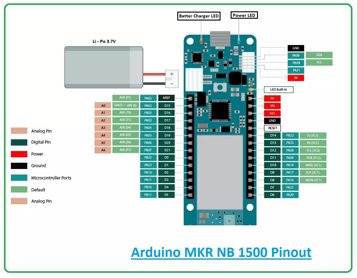
Introduction to Arduino USB Host Shields

Hello Everyone! Hope you’re well today. I welcome you on board. In this post today, I’ll walk you through the Introduction to Arduino USB Host Shields. With Arduino USB host shield you can interface the USB device to your Arduino board. This USB host shield is based on MAX3421E which is mainly known as the USB host controller that contains the analog circuitry and digital logic required to apply the USB full speed peripheral to USB specifications rev. 2.0. Moreover, this shield is compatible with TinkerKit which projects you can plug this TinkerKit module with the Arduino Boards.

Introduction to Arduino USB Host Shields

  • Arduino USB host shield is used to connect a USB device with the Arduino Board. Simply put, USB host shields provide the USB host capabilities to the Arduino boards.
  • With this USB host shield, you can connect any USB device with the Arduino boards.
  • What does this USB host mean? To understand this, you need to understand the USB protocol that comes with two types of devices. One is called the peripheral (client) and the other is called a host (server).
  • When the mouse or keyboard is attached to the computer through a USB port, your system acts as a host and the keyboard acts like a peripheral (client).
  • Successful communication is carried out using this USB protocol when one of the devices acts like a host which indicates you cannot attach two keyboards for the communication because both are peripheral devices.
  • The USB Host shield incorporates MAX3421E which is a separate chip that is mainly used to provide the USB host support to the Arduino board.
  • Once you connect this shield with the Arduino board, the board starts behaving like a host with you can attach other peripheral devices like a keyboard or mouse.
  • USB host shield is normally installed on the top of the Arduino boards.

Device Classes

The shield supports the following device classes.
  • Game controllers = Nintendo Wii, Sony PS3, Xbox360.
  • ADK-capable Android phones and tablets.
  • Bluetooth dongles.
  • USB to serial converters = FTDI, PL-2303, ACM, as well as certain cell phones and GPS receivers.
  • Mass storage devices: External hard drives, memory card readers, USB sticks.
  • Digital cameras: Powershot, Canon EOS, generic PTP, Nikon DSLRs and P&S
  • HID devices = keyboards, joysticks, mice, etc.

MAX3421E USB Peripheral/Host Controller with SPI Interface

  • Recall, MAX3421E chip known as the USB host controller that contains the analog circuitry and digital logic required to apply the USB full speed peripheral to USB specifications rev. 2.0.
  • This chip comes with a built-in transceiver that contains ±15kV ESD protection with programmable USB disconnect and connect.
  • SIE stands for (serial interface engine) which is mainly employed to control the low-level USB protocol details including bus retries and error checking.
  • The SPI interface can access the register set which is used to operate the chip and works at the frequency 26MHz.
The following figure shows the pinout diagram of the chip.
  • When MAX3421E operates as a host it provides a huge collection of USB peripherals to DSP, ASIC, and microprocessor.
  • The SPI interface operates at a voltage between 1.4V and 3.6V due to the internal level translators.
  • The MAX3421E comes in a 32-pin TQFN package (5mm x 5mm) and 32-pin TQFP package (5mm x 5mm) with operating temperature range from -40°C to +85°C

MAX3421E Datasheet

Before you apply any component to your electrical project, it’s wise to go through the datasheet of the component that contains the main characteristics of the device. Click the link below to download the datasheet of MAX3421E.

Applications

  • Embedded Systems
  • Microprocessors and DSPs
  • Medical Devices
  • Cameras
  • PDAs
  • Custom USB Devices
  • PLCs
  • MP3 Players
  • Set-Top Boxes
  • Instrumentation
  • Desktop Routers
That’s all for today. I hope you have enjoyed reading this article. If you’re unsure or have any questions you can approach me in the section below. You’re most welcome to share your valuable feedback and suggestions around the content we share so we keep producing quality content customized to your exact needs and requirements. Thank you for reading the article.

Introduction to Arduino Pico

Hi Friends! I welcome you on board. Happy to see you around. In this post today, I’ll walk you through the Introduction to Arduino Pico.

Arduino Pico is the world’s smallest Arduino compatible board, as said by Arduino Official Page. Because of its small size & low weight, it is normally used in autonomous projects i.e. drones, robots, quadcopters etc. where size is the real issue.

Arduino boards are introduced in modern electronics, to make projects economical and easy to design. A common man with no prior knowledge about programming can get hands-on experience with them. This smallest Pico version is readily available to turn your innovative thoughts into reality.

I suggest you read this post all the way through as I’ll detail the complete Introduction to Arduino Pico covering datasheet, pinout, features, pin description, programming and communication and applications.

Let’s get started.

Introduction to Arduino Pico

  • Arduino Pico is a small-sized(0.6" x 0.6"), breadboard-friendly and Arduino-Compatible Microcontroller board, based on Atmega32u4 Microcontroller, contains 15 pins onboard and developed by MellBell Electronics(a Canadian company confounded by MOHAMMAD MALHAS & AHMAD NABEL).
  • Leonardo compatible bootloader is pre-installed in Arduino Pico.
  • The small size of 0.6” x 0.6” and 1.1g weight is what makes it special for a range of autonomous applications i.e. quadcopters, robots, automation etc.
  • Arduino Pico comes with 8 digital input/output pins.
  • It also contains 3 analog I/O pins used for interfacing analog sensors.
  • Out of 8 digital pins, 1 Pin can also be used for generating PWM pulses and its Pin # D3.
  • Arduino Pico board operates at 5V while the input voltage ranges from 7V to 12V.
  • The maximum current rating of Arduino Pico is 40mA, so we can't attach a load drawing more current than that.
  • The board also contains one micro USB Type-B Port, a reset button and a Reset pin.
  • Arduino Pico supports two types of Communication Protocols: (We will discuss them later in detail)
    • Serial Protocol.
    • SPI Protocol.
  • The flash memory is 32KB out of which 4KB is used by Bootloader. It is the memory where the sketch is stored. (The code we compile on Arduino IDE software is called a sketch)
  • It comes with an SRAM memory of 2.5KB, it's even greater than that of UNO(where SRAM is 2KB).
  • It has a crystal oscillator of 16MHz, so it's as fast as UNO or Nano.
  • On its Kickstarter page, it's available in multiple colors(around 20 different colors).
  • Mellbell also offers an aluminum version of the board that can be used in overheated environments and applications.

Arduino Pico Datasheet

Before you apply this board to your embedded project, it’s wise to scan through the datasheet of the device that features the main characteristics of the board. You can download the datasheet of Arduino Pico by clicking the link below:

Arduino Pico Features

The following are the main features of the Arduino Pico board.
  • Based on the ATmega32u4 microcontroller,
  • Runs at a clocked frequency of 16 MHz
  • 40 mA DC current per I/O pin
  • 2.5KB of SRAM memory
  • Bootloader: Leonardo compatible
  • Reset: 1 pin
  • 3 SPI pads on the back of the board
  • 32 kB of internal Flash (4 kB used by the bootloader)
  • 8x digital I/O pins, 1x PWM channel, and 3x analog input channels.
  • The operating voltage is 5V.
  • Input voltage range = 7 to 12 V.
  • 6 x 0.6 inches size. Weight of 1.1 grams
  • Bootloader compatible with the Arduino Leonardo

Arduino Pico Pin Description

  • Hope you’ve got a sneak peek of this smallest Arduino board. In this section, we’ll detail the pin description of the pins installed on the board.

Analog Pins

  • There are 3 analog pins available on the board. These pins can get any number of values in opposed to digital pins which get only two values i.e. HIGH and LOW.

PWM Pins

  • This board incorporates one PWM channel which is employed to receive some of the analog output’s functions. When the PWM is activated, the board generates analog results with digital means.

Digital Pins

  • Total 8 digital pins are employed on the board. These pins are introduced to be configured as inputs or outputs according to the requirement. These pins remain ON or OFF. When they are in the OFF state they are in a LOW voltage state receiving 0V and they are in HIGH voltage state they receive 5V.

Atmega32u4 Pinout

  • The following figure represents the pinout diagram of Atmega32u4.

Atmega32u4 Pin Description

  • In this section, we’ll detail the pin description of each pin available on Atmega32u4.

Vcc

  • Digital voltage supply pin.

GND

  • Ground Pin.

Port B (PB7...PB0)

  • Port B is attached with pull-up resistors and is an 8-bit bidirectional I/O port. The pull up resistors are mainly employed to limit the current. This port is more efficient and contains better driving capabilities compared to other ports.
  • When the pull up resistors are activated in this port C, it will source current with port pins extremely pulled low.

Port C (PC6, PC7)

  • Port C is an 8-bit bidirectional I/O port that contains pull-up resistors.
  • When the pull up resistors are activated, Port C is used to source current with port pins extremely pulled low - Similar to Port B.

Port D (PD7..PD0)

  • Port D is a bi-directional 8-bit I/O port with pull-up resistors. When the reset condition is activated, the Port D pins are tri-stated.

Port E (PE6, PE2)

  • Only two bits PE6 and PE2 are available on the product pinout. It is an 8-bit bidirectional port that features internal pull up resistors to limit the current.

Port F (PF7..PF4, PF1,PF0)

  • Port F is a bidirectional port that serves as analog inputs for the A/D converter. Two bits PF2 and PF3 are not available on the device pinout.

D+

  • USB Full speed / Low Speed Positive Data Upstream Port. It is connected to the USB D+ connector pin employed with the serial resistor 22W.

D-

  • USB Full speed / Low Speed Negative Data Upstream Port. It must be connected to the USB D- connector pin incorporated with serial resistor 22W.

UGND

  • This is USB pads ground.

UCAP

  • USB Pads Internal Regulator Output supply voltage.

UVCC

  • USB Pads internal regulator Input supply voltage.

VBUS

It is USB VBUS monitor input.

XTAL1

  • Input to the inverting Oscillator amplifier and Input to the internal clock operating circuit.

XTAL2

  • Output from the inverting Oscillator amplifier.

RESET

  • A reset pin. When a low level applied to this pin for a longer period of time, it produces a reset. It is important to note that shorter pulses may not generate a reset.

AVCC

  • AVCC is the supply voltage pin for all the A/D Converter channels.

AREF

  • This pin is utilized as the analog reference pin for the A/D Converter.

Communication and Programming

  • The module comes with different communication protocols including I2C, and UART.
  • The UART is a serial communication protocol that carries two lines Tx and Rx where the former is a transmission line used to transfer the serial data and the latter is a receive data line used to receive the serial data.
  • The I2C is a two-wire communication protocol that contains two lines named SCL and SDA. The SCL is a serial clock line that is used for the synchronization of all data transfer over the I2C bus while SDA is a serial data line mainly used to carry the data.
  • Arduino IDE is the professional software developed by Arduino.cc that is used to program all types of Arduino Boards.
  • Connect the board through USB to the computer and test and program the board as you like better.

Arduino Pico Applications

  • Creating a wireless keyboard
  • Water level meter.
  • Health and security systems
  • Student projects
  • Embedded systems
  • Industrial automation
  • Automatic pill dispenser
It is important to note that all Arduino boards are microcontrollers but not all microcontrollers are Arduino boards. Due to its small size and easy to use functions, most people prefer Arduino boards over microcontrollers. Moreover, you don’t need to include extra peripherals while using these boards, as they come with built-in functions that don’t require the addition of external components. That’s all for today. I hope you’ve enjoyed reading this article. If you’re unsure or have any questions, you can approach me in the section below. I’d love to help you the best way I can. You’re most welcome to share your valuable feedback and suggestions around the content we share so we keep sharing quality content customized to your exact needs and requirements. Thank you for reading the article.

Introduction to Arduino Beetle

Hi Friends! Hope you’re well today. I welcome you on board. In this post today, I’ll walk you through the Introduction to Arduino Beetle. Arduino beetle is the smallest Arduino board that comes with the functionality of Arduino Leonardo. This board is a remarkable addition to the minimalistic Arduino technology. It is based on the microcontroller Atmel Atmega32u4. With the inception of innovations in modern technology, electronic devices are becoming light, more compact that happen to perform a lot of functions. These devices are economical and require little to no prior knowledge to get your hands dirty with them. All Arduino boards are microcontrollers but not all microcontrollers are Arduino board. While using the Arduino board, you don’t need to attach extra peripherals with the board, as it comes with built-in functions that don’t require the addition of external components. Earlier we have shared the articles on scores of Arduino boards including Arduino Uno, Arduino Leonardo, Arduino Due, and Arduino Mega. You can check these articles to find the basic information about them. I suggest you buckle up, as I’ll walk you through the complete introduction to Arduino Beetle covering datasheet, pinout, pin configuration, features, communication and programming and applications. Let’s jump right in.

Introduction to Arduino Beetle

  • Introduced by Arduino.cc, Arduino Beetle is the smallest Arduino Leonardo board that is based on Atmel Atmega32u4.
  • The Atmega32u4 is an 8-bit CMOS low power microcontroller
  • Arduino.cc offers an open-source platform for everyone which means you can optimize the boards and software programs as you like better.
  • The IDE (integrated development environment) is a software used to program the Arduino board. You don’t require prior knowledge and technical skills to start working with this board. The C and C++ are the languages used to program the Arduino beetle.
  • Though IDE software is compatible with MAC, Windows, or Linux Systems, Windows is a preferable operating system to use this board.
  • This tiny device comes with a micro USB port which means you can directly connect the device with the computer and program it based on your needs and requirements.
  • You don’t need a separate burner to burn and run the program on the board as it comes with a pre-burned Bootloader that allows you to upload the code in the hex file of the board.
  • The beetle is mainly introduced to provide the solution for low-cost disposable projects including DIY, gift projects, student projects, and e-textile.
  • This device operates at 5V and it also functions at 3.7V. Make sure voltage doesn’t exceed 5V else it can damage the device.
  • It comes with a clock time 16MHz. Several pins are incorporated on board out of which 10 are digital pins, 4 are PWM pins and 5 are analog pins.
  • This module comes with a crystal oscillator frequency up to 16 MHz that is mainly used to produce the clock pulses with decent speed. This oscillator is required for the synchronization of all the internal operations.
  • This module supports different communication protocols including I2C and UART.
  • The flash memory is 32KB out of which 4KB is used by the Bootloader. It is the memory where the sketch (the program we create on IDE is called a sketch) is stored.
  • The SRAM memory is 2.5KB which is the memory where sketch manipulates and produces variables when it operates. And EEPROM memory is 1KB and it is the space used for storing long-term information.
  • The price of this board at the time of writing this article is around 8$ which carries all powerful functions like Arduino Leonardo.

Arduino Beetle Datasheet

Before you incorporate this device into your electrical project, it’s wise to go through the datasheet of the device that features the main characteristics of the board. Click the link below to download the datasheet of Arduino beetle.

Arduino Beetle Features and Specifications

The following are the main features and specifications of Arduino beetle.
  • Board size 20mm x 22mm.
  • Direct testing and uploading program through a micro USB port.
  • I/O ports are V-shaped gold plated.
  • Two power interfaces that are gold plated and are used to supply power to the board.
  • Blue Light blink indicator which indicates the operation of the board.
  • Incorporated with Atmel Atmega32u4 microcontroller.
  • The operating voltage is 5V and the clock speed is 16MHz.
  • There are 5 analog pins, 4 PWM pins, and 10 digital pins on board.
  • Micro USB = 1
  • UART = 1
  • I2C = 1
  • EEPROM = 1KB
  • SRAM = 2.5 KB
  • Flash Memory = 32KB out of which 4KB is used by the Bootloader.
  • Write/Erase Cycles: 10,000 Flash/100,000 EEPROM
  • Data retention: 20 years at 85°C/ 100 years at 25°C

Arduino Beetle Pin Configuration

Still, reading? Perfect. I hope you’ve got a clear idea about this board. In this section, we’ll cover the pin description of the pins incorporated on the board.

Analog Pins

There are 5 analog pins incorporated on the board. These pins can receive any number of values in contrast to digital pins which receive only two values HIGH and LOW.

PWM Pins

This board doesn’t incorporate DAC (digital to analog converter) but it does incorporate 4 PWM pins which are used to get some of the analog output’s functions. During this PWM (pulse width modulation) process, the board generates analog results with digital means.

Digital Pins

There are total 10 digital pins incorporated on board. These pins are developed to be configured as outputs or inputs based on the requirement. These pins are either ON or OFF. When they are ON they are in HIGH voltage state getting 5V and when they are OFF they are in LOW voltage state getting 0V.

Atmega32u4 Pinout

The following figure shows the pinout diagram of Atmega32u4.

Atmega32u4 Pin Description

In this section, we’ll cover the pin description of each pin incorporated on Atmega32u4.

Vcc

It is a digital voltage supply pin.

GND

This pin is connected to the ground.

Port B (PB7...PB0)

Port B is an 8-bit bidirectional I/O port that is incorporated with pull-up resistors. These resistors are used to limit the current and prevent it exceeding from a certain number. This port comes with efficient driving capabilities compared to other ports. When this port is used as an input, this will source current due to the port pins that are extremely pulled low. This happens when the pull-up resistors are activated.

Port C (PC6, PC7)

Port C is similar to Port B - an 8-bit bidirectional I/O port incorporated with pull-up resistors. When the pull up resistors are activated, Port C will source current with port pins extremely pulled low.

Port D (PD7..PD0)

Port D is an 8-bit bidirectional I/O port that comes with pull-up resistors. When the reset condition meets, the Port D pins are tri-stated.

Port E (PE6, PE2)

Only two bits... PE6 and PE2 are present on the device pinout. It is an 8-bit bidirectional port incorporated with internal pull-up resistors.

Port F (PF7..PF4, PF1,PF0)

Port F is a bidirectional port that acts like analog inputs to the A/D converter. Two bits PF2 and PF3 are not present on the product pinout.

D-

USB Full speed / Low Speed Negative Data Upstream Port. It should be attached to the USB D- connector pin along with the serial resistor 22W.

D+

USB Full speed / Low Speed Positive Data Upstream Port. It is connected to the USB D+ connector pin along with the serial resistor 22W.

UGND

USB pads ground.

UVCC

Regulator Input supply voltage applied to USB pads.

UCAP

Internal Regulator Output supply voltage applied to USB pads.

VBUS

USB VBUS monitor input.

RESET

This is a reset pin. A low level applied to this pin for a longer time will produce a reset. Shorter pulses may not generate a reset.

XTAL1

Input to the internal clock operating circuit and Input to the inverting Oscillator amplifier.

XTAL2

Output from the inverting Oscillator amplifier.

AREF

This is used as the analog reference pin for the A/D Converter.

AVCC

AVCC is the supply voltage pin for all the A/D Converter channels.

Communication and Programming

  • Recall, this module supports different communication protocols i.e. I2C, and UART.
  • The I2C is a two-wire communication protocol that carries two main lines called SCL and SDA. The former is a serial clock line required for the synchronization of all data transfer over the I2C bus. While the latter is a serial data line mainly employed to carry the data.
  • And the UART is mainly used for serial communication and comes with two lines Tx and Rx where the former is used to transfer the serial data and the latter is used to receive the serial data.
Arduino IDE software is used to program all types of Arduino Boards. Attach micro USB to the Beetle and select Arduino Leonardo from your board type on the Arduino IDE software.

Arduino Beetle Applications

This tiny little beast is a full system in a small package as it incorporates almost all functions like Arduino Leonardo. The following are some applications of Arduino Beetle.
  • Health and security systems
  • Creating a wireless keyboard
  • Industrial automation
  • Embedded systems
  • Student projects
  • Automatic pill dispenser
  • Water level meter.
You’ll find a lot of microcontrollers in the market that are more economical than the Arduino board. But still, most of the hobbyists and students prefer Arduino Board over microcontroller. The reason is clear. Arduino board comes with a big community that shares expertise and knowledge for a wide range of audiences. Help is readily available that you’ll never find in the case of microcontrollers. Moreover, when you select Arduino board over microcontroller, you don’t need additional components and extra peripherals to connect with the board, as this board comes with a lot of built-in functions, setting you free from the hassle of connecting a lot of components. Simply, you need to plug the device with the computer and play with it on the fly. That’s all for today. I hope you’ve enjoyed reading this article. If you’re unsure or have any questions, you can pop your comment in the section below, I’d love to help you the best way I can. Feel free to share your valuable suggestions and feedback around the content we share so we keep coming up with quality content customized to your exact needs and requirements. Thank you for reading the article.

Interfacing Flame Sensor with Arduino

Hello everyone! I hope you all will be fine and having fun. Today I am going to tell you that how can you make a simple program for Interfacing Flame Sensor with Arduino. Flame sensor is used in offices, home and at different places to detect the fire. First of all I would like to tell you about the working principle of the flame sensor. Flame sensor is a device designed for the detection of the fire and to respond it. They are usually designed for the detection of most frequently used industrial fuel e.g. diesel, gasoline, karosene, ethylene, hydrogen etc. They are designed in way to distinguish between the radiations from the sunlight and the actual flames. There different types of flame sensors e.g. Ultraviolet (UV) detectors, Infrared (IR) flame detectors, UV/IR detectors, IR/IR flame detectors, closed circuit video cameras. The purpose of these all flame detectors/sensors is almost similar i.e. to detect the fire and responding quickly to it. The flame sensors have a wide range of applications in our daily life e.g. fume cupboards, felt manufacture, nuclear industry, pharmaceutical industries, printing, spray booths, generator, storage tanks, industrial heating and drying systems etc.
Where To Buy?
No.ComponentsDistributorLink To Buy
1Flame SensorsAmazonBuy Now
2Arduino UnoAmazonBuy Now

Interfacing Flame Sensor with Arduino

In this section of the tutorial Interfacing Flame Sensor with Arduino, I will explain you the step by step procedure to make a simple algorithm or program in Arduino software for the interfacing of flame sensor with Arduino. The algorithm is pretty simple. I will set a threshold limit, when the temperature exceeds that limit, an LED will be turned on to show the there is something wrong. You can also attach a buzzer with the Arduino. When the fire will be detected buzzer will be turned on automatically. First if all I would like to share the complete source code for Interfacing Flame Sensor with Arduino with all of you guys.
  • You can download the complete source code here by clicking on the button below.
  • Just download the .rar file, extract it and enjoy the complete simulation.

Components Required

Here, I am going to show you the list of all the components used in this project.
  • Arduino UNO
  • Flame Sensor
  • LED
  • Soldering Iron
  • Soldering Gum
  • Power Supply (12V)
  • Jumper Wires
  • Varrow Board
Brief Description of the Components
  • Arduino UNO acts as the back bone of the project. It manipulates the whole source code uploaded to the board, prints the desired data on the serial monitor and also prints the executed commands on the LCD. Arduino UNO is shown in the figure below.
  • Power Supply of 12V is used to turn the entire system ON. Because, we can not test and verify our system until we have not switched it ON. Power supply used for this project is shown in the figure below.
  • Jumper Wires are used to make the connections of the all the components in order to make the complete circuit with proper working. Jumper wires are shown in the figure below.
  • Flame Sensor is used for the detection of the temperature and for showing the immediate response when the temperature is above the threshold. Flame sensor is shown in the figure below.
Circuit Diagram
  • Circuit diagram for the tutorial Interfacing Flame Sensor with Arduino is shown in the figure below.
  • You can run this project properly, by making the circuit first, identical to the circuit diagram shown in the figure above.
  • The analog pin A5 of the Arduino UNO will help us in reading the data from the sensor.
  • The other two pins of the sensor are connected to the supply of 5V and ground respectively as you can see from the above figure.

Block Diagram

  • The block diagram for the project Interfacing Flame Sensor with Arduino is shown in the figure below.
  • Power supply is provided in order to run the project properly.
  • Arduino is the backbone of the whole system and controls all of the devices used.
  • When the temperature crosses the adjusted threshold the LED will be turned ON to indicator that the fire is detected.
  • In normal condition LED will remain Off.

Source Code Descritption

  • Source code for Interfacing Flame Sensor with Arduino is given below.
  • Just copy the entire code and paste it in your Arduino software and upload it to the Arduino board.
#include<SoftwareSerial.h>//library for software serial object

int sensorPin = A0; // flame sensor is attached to A0 pin of Arduino

int sensorValue = 0; // Initial value of the sensor is 0

int led = 9; // an LED is attached to the pin no 9 of Arduino

void setup() //method used to run the code for the one time
{

pinMode(led, OUTPUT);//changint the mode of LED as an output

Serial.begin(9600);//rate at which arduino communicates with laptop

}

void loop()//method used to run the code repeatedly

{

Serial.println("Welcome to TechPonder Flame Sensor Tutorial");//prints on the serial monitor

sensorValue = analogRead(sensorPin);//reads the analog data from the sensor

Serial.println(sensorValue);//prints the sensor data on serial monitor

if (sensorValue < 100)//threshold for the LED indication

{

Serial.println("Fire Detected");//prints on the serial monitor

Serial.println("LED on");//prints on the serial monitor

digitalWrite(led,HIGH);//turning on the LED

delay(1000);//delay of 1 second

}

digitalWrite(led,LOW);//turning of the LED

delay(sensorValue);

}
  • First of all I have declared library of software serial.
  • Then I have defined the pins of Arduino UNO at which the flame sensor and LED are connected.
  • Then I have changed the mode of LED to output.
  • Then I have started reading the analog data from the flame sensor.
  • I have adjusted a threshold, when the temperature exceeds that value LED will be turned on.
  • When the temperature is below the threshold LED will remain off e.g in normal conditions.
So, that is all from the tutorial Interfacing Flame Sensor with Arduino. I hope you enjoyed this tutorial. If you face any sort of problem you can ask me in comments anytime without even feeling any kind of hesitation. I will try my level best to solve your issues in a better way, if possible. I will explore Arduino by making different projects on it and will share all of them with you as well in my later tutorials. Till then, Take care :)

Interfacing Temperature & Humidity Sensor with Arduino

Hello everyone! I hope you all will be absolutely fine and having fun. In the tutorial Interfacing Temperature & Humidity Sensor with Arduino I will tell you that how can you interface temperature and humidity sensor named as DHT11 with Arduino and how can you observe the temperature and humidity level using this sensor. This sensor has usually three pins but some of its types has four pins but only the three pins are of importance for us e.g. VCC, GND and the third pin for reading the data from the sensor. In the tutorial Interfacing Temperature & Humidity Sensor with Arduino, I will make a simple Arduino program which will estimate the level of temperature and humidity continuously and will display the value of both temperature and humidity on the serial monitor. You will see that the sensor will give different readings for the different environments.
Where To Buy?
No.ComponentsDistributorLink To Buy
1LCD 16x2AmazonBuy Now
2DHT11AmazonBuy Now
3Arduino UnoAmazonBuy Now

Temperature & Humidity Sensor with Arduino

I will tell you the step by step procedure that how can you interface DHT11 sensor with Arduino and how to make a simple program in Arduino software to read the data continuously from the sensor and how to display the obtained data on the serial monitor. You can also display this data on Liquid Crystal Display (LCD) as I have discussed in detail in my previous tutorial DC Motor Direction Control using Arduino, DC Motor Speed Control using Arduino, Stepper Motor Direction Control in Arduino and Stepper Motor Speed Control using Arduino.
  • You can download the complete source code here by clicking on the button below.
  • Download .rar file, extract this file and enjoy the complete simulation code.

Block Diagram

  • First of all, I would like to explain you the algorithm with the help of a block diagram.
  • It will help in better understanding of an algorithm.
  • The block diagram for interfacing of temperature and humidity sensor with Arduino is given in the figure below.
  • Power supply in necessary to turn the whole system ON.
  • DHT11 is connected with the Arduino UNO.
  • Arduino UNO reads the data from the DHT11 sensor and displays the obtained data on the serial monitor.
  • That data will also be displayed on the LCD.

Circuit Diagram

  • The complete wiring diagram for this project is shown in the figure below.
  • You can run this project properly, by making the circuit first, identical to the circuit diagram shown in the figure above.
  • The analog pin A3 of the Arduino UNO will help us in reading the data from the sensor.
  • The other two pins of the sensor are connected to the supply of 5V and ground respectively as you can see from the above figure.

Flow Chart

  • The flow chart will help you to understand the flow of the program while executing.
  • The flow chart for this project is shown in the figure below.
  • The data from the sensor can be estimated on the serial monitor only after opening the serial port
  • Then data will be displayed on the LCD and at end serial port must be closed in order to avoid the exchange of unwanted commands.

Source Code Description

  • The source code for this project is given below.
  • You have to just copy and paste the code given below in your Arduino software after properly interfacing DHT11 with the Arduino.
  • After uploading the code onto your Arduino board you will be able to observe the humidity and temperature and humidity level on serial monitor.
#include<dht.h>// DHT11 humidity sensor library
#include<LiquidCrystal.h> //LCD library
dht DHT; //Creating sensor object
#define DHT11_PIN A3 // Sensor is connected to Arduino pin 3
LiquidCrystal lcd(8, 9, 10, 11, 12, 13);// LCD connected with Arduino on these pins
void setup()
{
  Serial.begin(9600); //setting baud rate
  Serial.println("   =====================================================");
  Serial.println("   ||   Welcome to Temperarue and Humidity Detector   ||");
  Serial.println("   =====================================================");
  Serial.println("");
  lcd.begin(20, 4); // initialinzing the LCD order
  lcd.setCursor(4,1); //Setting the cursor on LCD
  lcd.print("Welcome to");//printing on LCD
  lcd.setCursor(2,2);
  lcd.print("Humidity detector");
  delay(2000);//adding delay of 2 secons or 2000 msec
  }
void loop()//method used to run the code repeatedly
{
  int chk = DHT.read11(DHT11_PIN); //Reading data from sensor
  Serial.print(" Humidity = ");//prints on the serial monitor
  Serial.print(DHT.humidity);// prints obtained humidity on serial port
  Serial.print(" g/m^3");

  lcd.clear();//clears all the data on LCD
  delay(1000);//adding delay of 1 second
  lcd.display(); //starting the display of LCD after clearing
  lcd.setCursor(0,0);
  lcd.print("Humidity=");
  lcd.print(DHT.humidity);
  lcd.print(" g/m^3");
  
  Serial.print("    \tTemperature = ");//prints on the serial monitor
  Serial.print(DHT.temperature, 1);//prints obtained temperature on serial port
  Serial.println(" degrees");

  lcd.setCursor(0,1);
  lcd.print("Temperature=");//prints on LCD
  lcd.print(DHT.temperature, 1);//prints the obtained temperature on LCD
  lcd.print(" deg");

  lcd.setCursor(1,2);
  lcd.print("www.TheEngineering");
  lcd.setCursor(4,3);
  lcd.print("Projects.com");

  delay(2000);//adding the delay of 2 seconds
  }  
  • I am going to explain you that how this code is working!
  • First of all I have added the library in the libraries folder at the destination where the Arduino software is installed.
  • I have defined DHT11’s library in the source code then.
  • Then I have defined the library for LCD.
  • I have defined the pin at which DHT11 is attached with the Arduino board.
  • Then I have defined the Arduino pins at which the LCD in interface.
  • Then by opening the serial port I have started to print the level of temperature and humidity on the serial monitor as well as on the 20×4 LCD.
  • At the end, I have added the delay of 2 seconds so that the speed of the data to be printed on the serial monitor can be reduced to some extent in order to observe properly.
  • This was the brief description of the source code.
That is all from the tutorial Interfacing Temperature & Humidity Sensor with Arduino. I hope you enjoyed this tutorial. If you are facing any problem regarding any of my tutorials, you can ask me freely in the comments without even feeling any kind of hesitation, I will try my level best to solve you issues in a better way, if possible. I will explore Arduino by making further projects and will share them with you as well. So, till then, Take Care :)

Interfacing Arduino with HC-05

Hello friends, i hope you all are fine and enjoying. Today i am going to share a new tutorial which is Interfacing Arduino with HC05 Bluetooth module. First of all lets have a little introduction about HC-05 Bluetooth module. HC-05 is a bluetooth module, which was designed for wireless data communication. This little module is capable of both sending and receiving data but it performs only one thing at a time, which means at a particular time it can only send or receive data but can't do the both tasks.

In order to send or to receive data, you have to make one module as a master and the other module as a slave. If both the modules are acting as master then, data will not transmit and if both the modules are acting as a slave then, again data will not transmit or receive. The hardware of Bluetooth module contains a large no of features. For example it is much sensitive and it is sensitive up to -80dBm and it catches a Bluetooth signal even from far away. If you wish to transmit data through it then, it also have much power to transmit data to a wider range. You can image its transmitting power from the digits that it has transmitting power of +4dBm. This module operates on a low voltages, that's why the power rating of this module is very low. The hardware of the module comes with a integrated antenna and also its hardware contains edged pins. These edged pins gives us the ease that it becomes very easy to plug in or plug out the wires. and also if you are going to use it within a circuit then, it becomes very easy to connect the cable with module. Above was a little introduction about Bluetooth module and its features. now lets move to the basic theme of our project, which is to do interfacing between arduino and HC-05.

Note:

  • If you have HC-06 or any other module in HC series then you don't need to get worried as they all work quite same. So you can also follow this tutorial for other HC series bluetooth modules.

Pin Configuration of HC-05

HC-05 Bluetooth module has total 6 pins. A simple HC-05  Bluetooth module is shown in the image given below and you can also see its pin configuration from this image. The pin configuration and the purpose of each pin is listed below as:

  1. They pin#1 is abbreviated a KEY pin. The function of this key is to show paired devices. In HC-05 module this pin is used to perform the module in AT mode.
  2. Pin#2 of HC-05  module is named as VCC pin. This module requires 3.3 volts to operate. If you will connect it directly with 5 volts then, this module will burn out.
  3. Pin#3 of this module is named as GND. At this pin the common ground of the circuit is provided.
  4. pin#4 is named as TXD. This pin is used when you have to transmit data to some external device. Asynchronous data transfer is performed by this module.
  5. pin#5 is named as RXD. This pin is used when the module have to receive wireless data from some external source. Asynchronous data is received through this module.
  6. The last pin of the module which is in fact pin#6 of the module and it is named as STATUS pin. The basic function of this pin is to check the status of the Bluetooth module. If the module is connected to some other device then, output of the system becomes HIGH and if the connection of Bluetooth drops then, this module generates a output pulse.

Interfacing with Arduino

So, now let's start with interfacing Arduino with HC05 bluetooth module. Its quite easy to interface as it works on Serial protocol. As mentioned above it has two pins named as TX and RX through which we can send or receive the data. Moreover, it works exactly the same as any mobile's bluetooth, you can connect your mobile with any device and can share data between these devices, similarly you can share the data with this device as well.
  • First of all, connect your HC05 bluetooth module with Arduino as shown in the below figure.
  • In the above figure, the connections are quite easy , we have provided power to the bluetooth module from Arduino and also connected TX pin of bluetooth module with RX pin of Arduino and RX pin of bluetooth module with TX of Arduino.
  • Now we are done with the connections so next part is to upload the code into Arduino.

Code for interfacing HC-05 with Arduino

Now upload the below code into your Arduino and you are ready to get the first data from your Bluetooth module.

Applications of HC-05 Module

  • The biggest application is that it is used to transmit or receive data wirelessly.
  • You can play your favorite sound tracks through bluetooth in your car using this module.
  • The modern Android phones contains a wireless GPS option. IN fact this module is being used in that phones and it works to seek the bluetooth location.
  • This module makes you able to chat with some android phone using Bluetooth.
Alright friends, that all for today. If you have any question, fell free to ask. Till next tutorial Take Care!!! :)

Introduction to Arduino Sensor Shield

Hi Guys! Hope you’re well today. I welcome you on board. Happy to see you around. In this post today, I’ll detail the Introduction to Arduino Sensor Shield. Arduino Sensor Shield is a board compatible with the Arduino Boards and comes with the standard header layout. It is used to connect sensors, servos, LCD with the Arduino board without soldering. This board is connected with the Arduino Board using the jumper wires. I suggest you read this post all the way through as I’ll be discussing the complete Introduction to Arduino Sensor Shield. Let’s get started.

Introduction to Arduino Sensor Shield

  • Arduino Sensor Shield is a board used to connect sensors, servos, LCD with the Arduino Board without the requirement of soldering.
  • Using Arduino Board separately you’ll find a few of 5V and GND connections. Arduino Sensor Shield gives you the ability of dedicated one 5V and GND connection for every Arduino signal pin.
  • Arduino.cc introduced the two versions of Arduino Sensor Shield i.e. V4 the old one and V5 the newer one. Both boards come with similar important connections, however, they appear different.
  • The V5 latest sensor shield comes with an external power connector, helping you get rid of the overloading of the Arduino board while working with too many actuators and sensors.
  • The 3-way male pin header is used to connect servo motors with the Arduino Board. This is a plug and play device. You can read data from the sensors connected with the shield and use it to drive servo motors with the Arduino boards.

1. Pins Distribution

Pins on the Sensor Shield are distributed into two main categories: a: Digital Pins b: Analog Pins

a. Digital Pins

Digital pins on the board are placed in the pack of three.
  • Where top pin represents GND (0V)
  • The middle pin represents Vcc (5V)
  • The bottom pin represents Signal (Arduino Digital Signal Pin No.)
The following figure shows the numbering of digital pins that are arranged from right to left on the board. The Digital Pins are configured from the following Arduino Language Instruction:
  • digitalWrite (Pin4,1);
And for reading following Arduino Language Instruction is used:
  • digitalRead(Pin4)

b. Analog Pins

The following figure shows the arrangement of Analog Pins that are sequenced from left to right.
  • Similar to digital pins, analog pins are also arranged in the pack of three.
  • Where the top one is GND (0V)
  • The middle one is Vcc (5V)
  • The bottom one is Signal (Arduino Analog Signal Pin No.)

2. Arduino Sensor Shield V5 Features

The following are the features of Arduino Sensor Shield V5.
  • The Arduino Sensor Shield V5.0 is used to connect sensors, servos, buttons, relays, and potentiometers with the Arduino Board. Incorporates IIC interface
  • Comes with RB URF v1.1 ultrasonic sensors interface
  • It is compatible with Arduino UNO and Mega Boards
  • Contains Bluetooth module communication interface
  • Carries SD card module communication interface
  • Contains APC220 wireless RF module communication interface
  • Carries 32 servo controller interface
  • Contains 128 x 64 LCD parallel interface

3. Connecting Sensors and Output Devices

When it comes to connecting the sensor shield with sensors and output devices, power pins must be connected the right way as follows
  • G goes to 0V or G or Gnd or GND on the sensor
  • V goes to 5V or V or Vcc or VCC on the sensor
  • S goes to the signal pin - IN or OUT
  • Some output-devices and sensors come with 2 signal pins (or more) with two or more 0V & +5V.
  • In that case pick one of the signal pins to connect the Signal, 0V, and +5V with the S, G, and V pins on the sensor shield and choose the S pins on another port for establishing the other signal connections.

4. Photo-Resistor Sensor

Some sensors like 4-wire Photo-resistor Sensor comes with 2 wires for power, as above, but carry two signal pins, one is marked as “DO” and another is marked as “A0” This is the same signal available in two versions.

a. Analog Signal

  • The AO is an analog signal that represents the light level where 0V shows the maximum light level and 5V shows the dark light.
  • analogRead instruction is used to read this signal and is commonly connected to the analog input of the sensor shield.
  • The A0 analog signal is read as 1023 for dark light and 0 for maximum light.

b. Digital Signal

  • The DO is a digital signal that represents the light level and is available in two different states i.e. logic low (0V) and logic high (5V)
  • The variable resistor available on the sensor module is used to set the switchover level. This digital signal is commonly connected to the digital input on the sensor shield.
  • The digitalRead instruction is used to read this signal where 1 represents the dark and 0 represents the light.
That’s all for today. I hope you find this read helpful. If you have any questions you can ask me in the section below. I’d love to help you the best way I can. Feel free to keep us updated with your valuable feedback and suggestions, they help us create quality content customized to your exact needs and requirements. Thank you for reading the article.

Introduction to Arduino Esplora

Hi Guys! Hope you’re well today. I welcome you on board. In this post today, I’ll walk you through the Introduction to Arduino Esplora. Looking like a videogame controller, the Arduino Esplora is an electrical device that contains an Arduino Leonardo board (microcontroller) and a number of outputs and inputs. There are a colored LED and a buzzer as outputs. And there is a light sensor, four buttons, a joystick, a microphone, an accelerometer, and a temperature sensor as inputs. In other words, it is just like another Arduino Board with integrated actuators and sensors. Just stay with me for a little while, as I’m going to document the complete Introduction to Arduino Esplora covering pinout, working, pin description, how it’s different than other Arduino boards, and applications. Let’s jump right in.

Introduction to Arduino Esplora

  • Introduced by Arduino.cc, the Arduino Esplora is an electrical device that is based on the Arduino Leonardo board and contains integrated actuators and sensors.
  • Similar to the Arduino Leonardo, the Esplora board is incorporated with an Atmega32U4 AVR microcontroller that carries a 16 MHz crystal oscillator.
  • The Esplora comes with onboard light and sound outputs, and many input sensors, like a temperature sensor, an accelerometer, a joystick, a slider, a light sensor, and a microphone.
  • It also contains two Tinkerkit input and output connectors to enhance its capabilities and a socket used for the LCD screen.
  • Arduino Boards like Arduino Esplora are developed to provide both hardware and software platforms in one place. You can control the board with Arduino software as you like better. Plug and play with the device without getting hands-on experience in electronics.
  • It can mimic a keyboard or mouse that gives you the ability to use it with any 3D software.
  • Arduino Esplora board contains two actuators and 11 inputs. It carries a light sensor, an accelerometer, a multiplexer, and a mic, an RGB LED, and a buzzer.
  • This board contains all built-in sensors and actuators, the reason it’s easy to program and easy to handle through Arduino IDE software.
  • The Arduino Esplora is a great package for beginners, with built-in features, giving you the ability to plug and play with the device and get desired results on the fly.
  • This board is not compatible with the Arduino Shields, but you can connect this device with the external LCD module.
  • To connect the other modules, this device carries two output and two input ports. These ports are compatible with the signal, voltage, and ground pins and are known as 2 pin TinkerKit ports.
  • The Arduino Esplora is an ideal pick for creating a remote control device for your electrical project. You can develop external communication with your project without any hassle.
  • A micro USB cable is attached to the board, and it carries almost everything to get you started without having to combine and assemble anything from outside.
  • Information is extracted from the inputs and is used to write the program in the software which is then used to control the outputs on the board or your computer just like a remote controller.
  • Arduino Esplora is compatible with the Arduino IDE (Integrated Development Environment) like other boards.
  • Plus, you can also run this device with Arduino Web Editor that is hosted online and is incorporated with the latest support and features for all boards. Read this guide on how to use this browser and upload your sketches online.
  • And if you want to use this board offline, you need to install the Arduino IDE desktop version.
  • This board contains everything built-in to get you started. You need to simply connect the board with the computer through USB cable and start your work.
  • The reset pushbutton is located at the upper left corner that is used to restart the board.
Esplora carries four LEDs as follows:
  • ON LED is colored green that identifies if the board is getting a power supply
  • Accessible through pin 13, L is a yellow LED that is directly connected to the microcontroller.
  • RX and TX are yellow LEDs that determines the information received or transmitted through USB communication.

Arduino Esplora Features

The following are the sensors available on the Esplora board:
  • Joystick
  • push-button of the joystick
  • microphone
  • light sensor
  • 2 TinkerKit input connectors
  • temperature sensor
  • 4 separate push-buttons
  • Accelerometer
The following are the actuators present on the board:
  • RGB LED
  • Buzzer
  • 2 TinkerKit connectors

Arduino Esplora Set up with Windows

  • First, you require a standard software developed by Arduino.cc known as Arduino IDE. This software is used to program and control the board through your system.
  • Now connect the board with the computer through micro USB that is used to transfer the program from the computer system to the board.
  • As you connect the cable the green power LED (labeled ON) will turn on and then the yellow LED will start glowing that is marked ‘L’. The yellow LED will go blinking on and off after 8 seconds indicating your board is connected with the computer.
  • When you connect the board, the Windows will automatically start its driver installation process. It the installation process doesn’t start automatically, go to the windows device manager then (Start > Control Panel > Hardware) and go to the Arduino Esplora listing. Right-click this listing and pick Update driver.
  •  At the next popped up window, select "Browse my computer for driver software", and click Next
  • Now click the ‘Browse’ option. It will return another window: find the folder with the Arduino software that you have installed. Choose the drivers folder and click OK, then click the ‘Next’ button
  • You will get a notification that reads, “the board has not passed Windows Logo testing.” Click on the option “Continue Anyway.”
  • After a while, a window will open that reads “Windows has finished installing the driver software for this device” Now click the ‘close’ button.
These instructions are for the system having Windows 7 operating system. If you have a MAC or Linux then read this post on how to connect Arduino Esplora with the system. All pictures placed here are from Arduino.cc

Applications

The following are the applications of Arduino Esplora.
  • Used in Arduino Wifi remote controller
  • Used in robotics and electronics
  • Incorporated to identify free-fall detection using an accelerometer
  • Employed to emulate mouse or keyboard
That’s all for today. I hope you find this read helpful. If you have any questions, you can approach me in the section below, I’d love to help you the best way I can. Feel free to keep us updated with your valuable feedback and suggestions, they help us generate quality work customized to your exact needs and requirements. Thank you for reading the article.

Arduino Mega 1280 Library for Proteus

Hi Guys! Hope you’re well today. Thank you for viewing this read. In this post today, I’ll walk you through the Arduino Mega 1280 Library for Proteus. You may already be familiar with Arduino Boards, in case you don’t, they are the open-source easy to use hardware and software platform used in modern electronic projects. These boards receive inputs and convert them into outputs to activate motors, LEDs, electrical circuits, robots, and embedded systems. They are mainly designed for newbies and non-tech geeks who hesitate to construct the electrical circuits from the get-go and hate diving into the nitty-gritty of architecting electrical wires accurately to fashion electrical circuits. Arduino boards come with both ready-made electronic kit and software program IDE (Integrated Development Environment) that runs on the computer. You only worry about the running code on your system, without involving into the hassle of organizing and connecting everything perfectly on your electrical circuit. We’ve already discussed the Arduino Mega 2560 Library for Proteus. Both Mega 2560 and Mega 1280 are almost similar in working and execution with a slight difference in flash memory and microcontrollers incorporated on the boards. Arduino Mega 2560 carries Atmega 2560 microcontroller with flash memory 256kb while Arduino Mega 1280 carries Atmega 1280 with flash memory 128kb. These boards can be powered by both USB cable and external power source where AC-to-DC adaptor or battery is used to power them externally. Our team is designing and adding these new libraries in the proteus library database to help students better understand the working of Arduino boards in proteus workspace. Check this post where we’ve shared Arduino Library for Proteus that includes six Arduino Boards in a single library. If you don’t have proteus installed in your PC, check this post covering how to download and install proteus software. This is the brief introduction of Arduino boards, let’s dive in to download the Arduino Mega 1280 library for proteus.

Arduino Mega 1280 Library for Proteus

Click the link below and download Arduino Mega 1280 Library for Proteus.
  • As you download this file, it will appear in zip format. Extract this file that houses two files named ArduinoMegaTEP.LIB and ArduinoMegaTEP.IDX.
Arduino Mega 1280 Library for Proteus
  • Copy and paste these two files in the library folder of proteus software.
  • After placing these files, start your proteus software, if it’s running already… restart. Now, click the ‘P’ button and look for the Arduino Mega 1280.
  • As you search this, it will return the figure below.
  • Select this file and click OK. As you click OK your cursor will start blinking with the Arduino Mega 1280, indicating you can place this board anywhere in the proteus workspace.
As you place this board in the proteus workspace, it will appear as below. Half work is done. Now we’ll include HEX file to run this board. To do this, right-click the board and select ‘edit properties’ or double click the board it will return window as below. Now browse the ‘PROGRAM FILE’ option to upload the HEX file. You can read this post in which I’ve briefly explained how to get a HEX file from Arduino.
  • This is how you can get Arduino Mega 1280 library for Proteus.
Now we’ll construct a simple LED blinking circuit with Arduino Mega 1280 in the proteus workspace.
  • We’ve designed a simple LED blinking circuit where we’ve attached LED with the pin 13 of the Arduino Mega 1280.
Open this blink example in the Arduino software and upload the HEX file. As you upload the HEX file and play the proteus software it will appear as figure given below. That’s all about How to download Arduino Mega 1280 Library for Proteus. You can use this library in your electronic projects. If you feel any difficulty in downloading this library, pop your comment in the section below, I’ll help you the best way I can. Feel free to share your suggestions about libraries you think should be a part of Proteus Library Database, I’ll design and include respective libraries. Thank you for reading this post.

Introduction to Atmega32

Hello friends, I hope you all are doing great. In today's tutorial, we are gonna have a look at detailed Introduction to Atmega32. ATmega32 is eight-bit higher enactment microcontroller, it is manufactured by an Atmel (it is a designer and builder of different semiconductors materials). It is founded on enriched RISC which stands for (Reduced Instruction Set Computing) design which consists of 131 (one thirty-one) potent commands. Mostly commands implement in one mechanism sequence. The maximum frequency at which it operates sixteen MHz. It delivers a subtle equilibrium among enactment and balance. It is the Pico Power sort of the normal ATmega328 kind which permits it to work below lesser voltage and power necessities, nearly 1.62 volts. In today’s post, we will have a look at its fortification, wreckage, eccentricity, privileges, etc. I will also share some links where I have related it with other microcontrollers. You can also get more material about it in comments, I will guide you more about it. So, let’s get started with a basic Introduction to Atmega32. 

Introduction to Atmega32

  • ATmega32 is eight-bit higher enactment microcontroller, it is manufactured by an Atmel (it is a designer and builder of different semiconductors materials).
  • It is a higher enactment, less power consuming eight-bit AVR (automatic voltage regulator) RISC (Reduced Instruction Set Computing) constructed microcontroller.
  • It syndicates thirty-two-kilo byte ISP (In-system Programming) flash storage which having rand and writes competences.
  •  This module consists of one-kilo byte  EEPROM (Electrically Erasable Programmable Read-Only Memory), two kilobyte SRAM (static RAM), 54 inputs and 69 general persistence output lines, thirty-two universal persistence functioning registers, a JTAG (Joint Test Action Group ) interfacing for border scanning and onboard repairing or debugging.
  • It also comprises of 3 malleable regulators with associate manners, interior and exterior interferes, sequential programmable USART (Universal Asynchronous Receiver and Transmitter), a (USI) having on state indicator, an eight-channel ten-bit analog to digital converter, programmable overseer timer with interior oscillation generator, SPI (Serial Peripheral Interface) sequential slot, and 5 software choose able power convertible manners.
  • It works on 1.8 to 5.5 volts.
  • It is very tranquil to program AVR (automatic voltage regulator) controller. As it has very substantial program storage so it can easily work with different embedded networks.
  • As this module consists of thirty-two inputs and output pinouts we can easily connect it with any other component effortlessly.
  • As we discussed earlier it has observer timer to reset fault, so it can be used on different networks for fault reset without any human interference.
  • As it has a lot of landscapes which cooperate with one other so we can use it in different controlling systems.
  • By performing influential commands in a solitary sequence, the expedient attains quantities impending 1 MIPS per MHz, balancing power consumption and processing speed.

Pinout of Atmega32

  • These are the main pinouts of ATmega32 which are described below.
    Pin# Type                                         Parameters
    Pin#1 PB0 (XCK/T0) it is the zero pin of port B.
    Pin#2 PB1 (T1) it is the one no pin of port B.
    Pin#3 PB2 (INT2/AIN0) it is the no two pin of port B.
    Pin#4 PB3 (OC0/AIN1) it is the three no pin of port B.
    Pin#5 PB4 (SS) It is the no four-pin of port B.
    Pin#6 PB5 (Master Out Slave In) It is the pin no five of port B.
    Pin#7 PB6 (master in slave out) It is the pin no six of port B.
    Pin#8 PB7 (Serial clock) this is the pin no seven of port B.
    Pin#9 RESET It is the reset pin.
    Pin#10 Vcc It is the supply voltage of plus five volts.
    Pin#11 GND It is the ground terminal.
    Pin#12 XTAL2 it is linked with the  Crystal Oscillator.
    Pin#13 XTAL1 this pin is also linked with the Crystal Oscillator.
    Pin#14 PD0 (RXD) it is the zero pin of port D.
    Pin#15 PD1 (TXD) It is the pin no one of Port D.
    Pin#16 PD2 (INT0) it is the pin no two of port D.
    Pin#17 PD3 (INT1) it is the pin no three of port D.
    Pin#18 PD4 (OC1B) it is the pin no four of port D.
    Pin#19 PD5 (OC1A) it is the pin no five of port D.
    Pin#20 PD6 (ICP) it is the pin no six of port D.
    Pin#21 PD7 (OC2) it is the pin no seven of port D.
    Pin#22 PC0 (SCL) it is the pin no zero of port c.
    Pin#23 PC1 (SDA) it is the pin no one of port c.
    Pin#24 PC2 (TCK) it is the pin no two of port c.
    Pin#25 PC3 (TMS) it is the pin no three of port c.
    Pin#26 PC4 (TDO) it is the pin no four of port c.
    Pin#27 PC5 (TDI) it is the pin no five of port c.
    Pin#28 PC6 (TOSC1) it is the pin no six of port c.
    Pin#29 PC7 (TOSC2) it is the pin no seven of port seven.
    Pin#30 AVcc It is the Vcc for interior ADC.
    Pin#31 GND it is the ground terminal.
    Pin#32 AREF It is the Analog Reference Pin for ADC.
    Pin#33 PA7 (A/DC7) it is the pin no seven for port A.
    Pin#34 PA6 (A/DC6) It is the pin no six for port A.
    Pin#35 PA5 (A/DC5) it is the pin no five for port A.
    Pin#36 PA4 (A/DC4) It is the pin no four for port A.
    Pin#37 PA3 (A/DC3) it is the pin no three for port A.
    Pin#38 PA2 (A/DC2) it is the pin no two for port A.
    Pin#39 PA1 (A/DC1) it is the pin no one for port A.
    Pin#40 PA0 (A/DC0) It is the pin no zero for port A.

Features of Atmega32

  • These are the main features of atmega32 which are explained below.
    • Its processor is eight bits AVR(automatic voltage regulator.
    • This module has forty different types of pinouts, which we have discussed with detailed.
    • it's working voltage is from plus four volts to plus five volts.
    • This device has thirty-two inputs and output pinouts.
    • This microcontroller has an analog to digital converter unit which ten bits resolution.
    • It consists of two counter first one is eight bits and other is sixteen bits.
    • This component has one analog comparing circuit. It does not consist of digital to the analog converter. It consists of four(4) pulse width modulator (PWM). It consists of the exterior oscillator which works on the eighth megahertz frequency. It also consists of the interior oscillator which works on eight megahertz frequency. It consists of Flash memory. Its processor speed is sixteen MIPS(Million Instructions Per Second). Its random excess memory is two-kilo bytes. It comprises of 6 power storing Ways. Its functioning temperature is -55 Celsius to 125 celsius.
    • Its working temperature is -55 Celsius to +125 Celsius.

Applications of ATmega32

There are many applications of Armega32 some are described here.
  • It used in different temperature control systems.
  • It used in the different analog signal calculation and management techniques.
  • It used in different entrenched schemes like chocolate apparatus, peddling mechanism.
  • It used for controlling the motor.
  • It used for Numerical signal handling.
  • It used for Marginal Interfacing scheme.
So, friends, it was all about ATmega32, if you have any question about it ask in comments I will resolve your problems and try my best to the simplest answer to your problem. Thanks for reading. Take care until the next tutorial.
Syed Zain Nasir

I am Syed Zain Nasir, the founder of <a href=https://www.TheEngineeringProjects.com/>The Engineering Projects</a> (TEP). I am a programmer since 2009 before that I just search things, make small projects and now I am sharing my knowledge through this platform.I also work as a freelancer and did many projects related to programming and electrical circuitry. <a href=https://plus.google.com/+SyedZainNasir/>My Google Profile+</a>

Share
Published by
Syed Zain Nasir