Traffic Signal Control using Arduino

Hello friends, hope you all are fine and having fun with your lives. Today, I am going to share a Traffic Signal Control using Arduino. Few days earlier, I have posted the same tutorial but it was Traffic Light Signal Using 555 Timer in Proteus ISIS and today we will do the same thing but using Arduino programming. Its quite a simple but good starting project on Arduino. So, if you are new to Arduino then must give it a try.

Traffic Signal Control is quite a usual thing. We see traffic signals daily on our roads and usually engineers are asked to design such projects in their initial semesters. If we look at the traffic signals then we can see they are simply turning ON and OFF lights at some fixed regular intervals. and the pattern is quite simple as well. so I have simply followed that pattern and design the code. You should also have a look at Arduino 3 Phase Inverter. So let's start with designing this project named as Traffic Signal Control using Arduino.

Traffic Signal Control using Arduino

  • First of all, design a circuit in Proteus for Traffic Signal Control using Arduino as shown in the below figure:
  • Its quite a simple project so the circuit is quite simple as well. You can see I have just placed an Arduino board and plugged three LEDs with it and obviously they are Green, Yellow and Red in color.
  • These LEDs are attached to pins 2,3 and 4 of Arduino UNO.
  • Now next step is to write the Arduino Code for Traffic Signal Control using Arduino, so I have written and it is shown below:
#define GreenLed 4 #define YellowLed 3 #define RedLed 2 void setup() { pinMode(GreenLed, OUTPUT); pinMode(YellowLed, OUTPUT); pinMode(RedLed, OUTPUT); } void loop() { digitalWrite(GreenLed, HIGH); digitalWrite(YellowLed, LOW); digitalWrite(RedLed, LOW); delay(5000);delay(5000); digitalWrite(GreenLed, LOW); digitalWrite(YellowLed, LOW); digitalWrite(RedLed, HIGH); delay(5000);delay(5000); digitalWrite(GreenLed, LOW); digitalWrite(YellowLed, HIGH); digitalWrite(RedLed, LOW); delay(3000); }
  • That's the complete code for this project Traffic Signal Control using Arduino and I think its quite self explanatory plus I have also changed the color accordingly.
  • First of all Green LED is ON and the rest are OFF which is shown in green color.
  • Next Red LED is ON and the rest are OFF after around 10 seconds which you can change by changing these delays.
  • Finally the Yellow LED will be ON and you can see it goes OFF just after 3 sec because it has short delay, you can change these delays quite easily.
  • Below is the flow chart of above programming for Traffic Signal Control using Arduino which will clear the theme properly.
  • Now compile your Arduino code and get the hex file.
Note:
  • Now when you upload the hex file into your Arduino, it will give output as shown below:
  • So that's how it will work, I hope you got this clearly as its quite simple, will meet you soon in the next tutorial. Till then take care!!! :)

Interfacing of RFID RC522 with Arduino

Hello friends, hope you all are fine and having fun with your lives. Today's post is about interfacing of RFID module RC522 with Arduino. RC522 is very simple yet effective module. It is an RFID module and is used for scanning RFID cards. Its a new technology and is expanding day by day. Now-a-days it is extensively used in offices where employees are issued an RFID card and their attendance is marked when they touch their card to rfid reader. We have seen it in many movies that when someone places ones card over some machine then door opens or closes. In short, its a new emerging technology which is quite useful.

I recently get a chance to work on a project in which I have to use RFID reader to scan cards. In this project I have used it for for student attendance so I thought to share it on our blog so that other engineers could get benefit out it.

Let's first have a little introduction of RFID and then we will look into how to interface RC522 with Arduino. RFID is the abbreviation of Radio frequency identification. RFID modules use electromagnetic fields to transfer data between card and the reader. Different tags are attached to objects and when we place that object in front of the reader, the reader reads that tags.Another benefit of RFID is that it doesn't require to be in a line of sight to get detected. As in barcode, the reader has to be in the line of sight to the tag and then it can scan but in RFID there's no such restriction. So, let's get started with Interfacing of RFID RC522 with Arduino.

You should also read:

Interfacing of RFID RC522 with Arduino.

Now let's start with the interfacing of RFID RC522 with Arduino. There are many different RFID modules available in the market. The RFID module, which I am gonna use in this project, is RFID-RC522. Its quite easy to interface and works pretty fine. This module has total 8 pins as shown in the below figure:

  • SDA
  • SCK
  • MOSI
  • MISO
  • IRQ
  • GND
  • RST
  • 3.3V
It normally works on SPI protocol, when interfaced with Arduino board. Interfacing of Arduino and RC522 module is shown in below figure:
  • The pin configuration is as follows:
  • Now, I suppose that you have connected your RFID module with Arduino as shown in above figure and table, which is quite simple. You just need to connect total 7 pins, IRQ is not connected in our case.
  • Now next step is the coding, so first of all, download this Arduino library for RFID RC522 module.
Note:
  • Its a third party library, we haven't designed it, we are just sharing it for the engineers.

  • Now coming to the final step. Upload the below code into your Arduino UNO.
#include <SPI.h> #include <MFRC522.h> #define RST_PIN         9 #define SS_PIN          10 MFRC522 mfrc522(SS_PIN, RST_PIN); void setup() { SPI.begin(); mfrc522.PCD_Init(); } void loop() { RfidScan(); } void dump_byte_array(byte *buffer, byte bufferSize) { for (byte i = 0; i < bufferSize; i++) { Serial.print(buffer[i] < 0x10 ? " 0" : " "); Serial.print(buffer[i], HEX); } } void RfidScan() { if ( ! mfrc522.PICC_IsNewCardPresent()) return; if ( ! mfrc522.PICC_ReadCardSerial()) return; dump_byte_array(mfrc522.uid.uidByte, mfrc522.uid.size); }
  • Now using this code, you can read the RFID no of your card quite easily. Now the main task is to use that number and distinguish them so for that I changed the dump_byte_array function a little, which is given below:
#include <SPI.h> #include <MFRC522.h> #define RST_PIN         9 #define SS_PIN          10 MFRC522 mfrc522(SS_PIN, RST_PIN); int RfidNo = 0; void setup() { SPI.begin(); mfrc522.PCD_Init(); } void loop() { RfidScan(); } void dump_byte_array(byte *buffer, byte bufferSize) { Serial.print("~"); if(buffer[0] == 160){RfidNo = 1;Serial.print(RfidNo);} if(buffer[0] == 176){RfidNo = 2;Serial.print(RfidNo);} if(buffer[0] == 208){RfidNo = 3;Serial.print(RfidNo);} if(buffer[0] == 224){RfidNo = 4;Serial.print(RfidNo);} if(buffer[0] == 240){RfidNo = 5;Serial.print(RfidNo);} Serial.print("!"); while(1){getFingerprintIDez();} } void RfidScan() { if ( ! mfrc522.PICC_IsNewCardPresent()) return; if ( ! mfrc522.PICC_ReadCardSerial()) return; dump_byte_array(mfrc522.uid.uidByte, mfrc522.uid.size); }
  • Now using the first code I get the card number for all RFID cards and then in second code I used these numbers and place the check now when first card will be placed it will show 1 on the serial port and so on for other cards.
  • So, what you need to do is to use the first code and get your card number and then place them in second code and finally distinguish your cards.
  • Quite simple and easy to work.
  • Hope I have explained it properly but still if you get any problem ask me in comments.

NRF24L01 Arduino Interfacing

Hello friends, I hope you all are fine and enjoying. I have been working on a project these days and one portion of my current project includes the NRF24L01 Arduino Interfacing. So, I thought why not share this knowledge with you people, I hope you will learn something new and more interesting. If you don't know much about it, then you should have a look at Introduction to NRF24L01.

Few days ago, I have also posted a tutorial on XBee Arduino Interfacing, in which we have seen how to make wireless communication between two XBee Modules which is also an RF module. So, now we are gonna have a look at How to make Wireless Communication between two NRF24L01 modules. I hope you are gonna enjoy this nrf24l01 arduino Interfacing. Here's the video demonstration of NRF24L01 Arduino Interfacing:

Basics of NRF24L01

Before staring this interfacing of Arduino with 24L01, lets have a little introduction of nrf24l01 module. NRF24L01 is, in fact, a Radio Transceiver module and it operates on 2.4 GHz frequency. This module is a by default half- duplex fabricated module and it has the capability to send and receive data simultaneously. It's a very cheap & small sized module but it's features are astonishing. For example this module is capable of sending from 1 to 25 bytes of raw data simultaneously and the data transmission rate is up to 1 mega bytes per second. If we summarize all the features of this small size but big capability module then, we can say that:

  • By using this NRF24L01 module we can send a message to a particular receiver.
  • We can receive a message from some particular sender. (remember as I told earlier, we can do both the steps simultaneously).
  • During sending the message through this module, we will have to specify the message sender's and receiver's address.
  • Also we will have to specify the size of that particular message, which we are going to transmit through this module.
  • In some particular applications, we also have to perform switching between the receiver and sending state. For example, if you are received a particular message then, we will stop the communication first and will read it and then you will send it. So in such situations, we have to perform the switching while sending or receiving data through this module.
Now above discussion was a brief introduction about NRF24l01 module. Now lets move towards the major theme of our project which is Interfacing of arduino with NRF24l01 module. Note:
  • I encountered a problem of "Failed, response timed out" with NRF24L01+ while interfacing it with Arduino, if you got the same problem then read this post Interfacing of NRF24L01+ with Arduino - Response Timed Out. This nrf24l01 arduino example will help you in understanding this Response Timed Out problem.

NRF24L01 Arduino Interfacing

Arduino is a very powerful and versatile microcontroller board and it gives us the ease to perform multitasking. NRF24l01 has total 8 pins. The pin configuration and the function of each pin is described below:
  • The very first pin is for GND and through the pin#1 of this module, ground is provided to module.
  • Pin#2 of this module is to provide power supply. This pin is designated as VCC. This module generally needs 1.9 to 3.6 volts for its operation. And in most cases we will apply 3 volts to it.
  • Pin#3 is designated as CE and it is used to select the mode of operation. Either you are using this module to transmit data or to receive data.
  • Pin#4 is designated as CSN and it is used to enable the SPI chip, embedded on the module.
  • Pin#5 is used to provide SPI clock to the module. When this pin is HIGH then, clock is enabled and when this pin is LOW then, the clock to this module is disabled.
  • Pin#6 is designated as MOSI and it is used to transmit data from this module to the external circuit.
  • Pin#7 is designated as MISO and if we wish to receive data through this module from any external source then, this pin is enabled.
  • Pin#8 is the last pin of this module and it is designated as IRQ pin.
In order to do this Arduino with NRF24L01 communication, you will need two Arduino boards and two NRF24L01 modules. Now I suppose that you have these 4 items in your hand. So, first of all, let's do the transmitter side of NRF24L01 Arduino Interfacing.
NRF24L01 As Transmitter
  • Connect your NRF24L01 with Arduino as shown in the below figure:
  • Total 7 pins of NRF24L01 will be connected while the 8th pin IRQ doesn't need to connect.
  • Now, next thing you need to do is to download this RF24 Library of Arduino and place it in the libraries folder of your Arduino software so that we could compile our code of nrf24l01 arduino example.

Arduino Library for NRF24L01

  • We haven't designed this library, we are just sharing it for the engineers to use it in their projects.
  • Now upload the below sketch into your Arduino which you want to act as Transmitter.
    #include <SPI.h>
    #include "nRF24L01.h"
    #include "RF24.h"

    RF24 radio(9,10);

    const uint64_t pipes[2] = { 0xF0F0F0F0E1LL, 0xF0F0F0F0D2LL };
    unsigned long Command = 1;
    void setup()
    {
    Serial.begin(57600);

    radio.begin();
    radio.setRetries(15,15);
    radio.openReadingPipe(1,pipes[1]);
    radio.startListening();
    radio.printDetails();
    radio.openWritingPipe(pipes[0]);
    radio.openReadingPipe(1,pipes[1]);
    radio.stopListening();
    }

    void loop(void)
    {
    radio.stopListening();

    radio.write( &Command, sizeof(unsigned long) );

    radio.startListening();

    delay(1000);
    }
  • In this code, I have marked the variable Command, this is the variable which I am sending via NRF24L01, rite now its value is 1 which you can change.
  • So, if you want to send 3 you can change its value to 3.
  • Now lets design the receiver side.
NRF24L01 As Receiver
  • Again connect your Arduino with NRF24L01 as shown in below figure. Its same as we did for Transmitter side.
  • Now upload this below code into the Receiver and you will start receiving the value coming from transmitter.
    #include <SPI.h>
    #include "nRF24L01.h"
    #include "RF24.h"

    RF24 radio(9,10);

    const uint64_t pipes[2] = { 0xF0F0F0F0E1LL, 0xF0F0F0F0D2LL };

    typedef enum { role_ping_out = 1, role_pong_back } role_e;

    const char* role_friendly_name[] = { "invalid", "Ping out", "Pong back"};

    role_e role = role_pong_back;

    void setup(void)
    {
    Serial.begin(57600);
    radio.begin();
    radio.setRetries(15,15);
    radio.openReadingPipe(1,pipes[1]);
    radio.startListening();
    radio.printDetails();
    radio.openWritingPipe(pipes[1]);
    radio.openReadingPipe(1,pipes[0]);
    radio.startListening();
    }

    void loop(void)
    {

    if ( radio.available() )
    {
    unsigned long data = 0;
    radio.read( &data, sizeof(unsigned long) );
    Serial.println(data);

    delay(20);
    }
    }
  • Now open your Serial Monitor of Receiver side and you will see that you are getting "1" in the Arduino Serial Monitor, which is the value of Command variable we set in the Transmitter side, as shown in below figure:
  • Its quite easy and I hope you will make it work in the first attempt but if you still got problem then ask in comments.
  • I will share more Arduino Projects on this RF module soon.
So, that's all for today and I hope now you can easily Interface Arduino with NRF24L01 and can do the RF communication. If you have any problem in this Interfacing of Arduino with NRF24L01 then ask in comments and I will try my best to resolve them. Take care. :)

Getting Started with Arduino Programming

Hello friends, i hope you all are fine enjoying. Today i am going to share a new project tutorial which is Getting Started with Arduino Programming. In the previous tutorial, which was titled as Getting started with Arduino Software, I have explained in detail the basics of Arduino software. How this software is installed and run.

Today's post is also related to arduino software but, the difference is that, in previous post we learn How to use the arduino software, What are the function keys of this software and Where to write the code(sketch) and after writing the sketch, how it is debugged. Now in today's post which is ' Getting started with Arduino Programming', we will see How a Code is written in Arduino software? What are the built-in functions of Arduino software? How comments are made in sketch? What are the main loops, used in Arduino programming? How pin selection is done in Arduino software? How Digital pins are controlled, which are embeded on Arduino board? To explain this whole software in detail, i have divided this tutorial into major parts and also their sub-parts. Above was a little introduction about what actually we are going to learn in this post. Now without wasting any further time on introduction (as i will be explaining each and every step in below tutorial) i think now we should move towards the actual learning of the Arduino software to use it for programming.

You should also read:

1- How to make Comments in Arduino Programming

  • I hope that you are a beginner and i will start to elaborate the soaftware from very beginning.
  • First of all open your Arduino software. Go to file menu, a new window will open, from there click on the Examples and then go the Basics.
  • After clicking on basics a third new window will open and it will be showing all the basic Arduino built-in basic functions.
Note:
  • If you haven't bought your Arduino UNO yet, then you can buy it from this reliable source:

  • For beginners the function named as blink is very useful, so i will also teach you from this basic level tutorial.
  • When you will click on 'blink' option then, a new window will open, which is shown in the image given below:
  • In the above shown image you can see that we have opened a basic level example from built in Arduino software.
  • Now under this heading title, i will explain how to make comments in Arduino programming?
  • This is in fact the syntax to make comments in your sketch.The above code is of very basic level and it elaborates how to blink a single led by using Arduino board.
  • If you look closely in the above image then you will see that some words are written in the start of the sketch and these words are encloses in these signs " /* ..........*/ ".
Note: Comments have no rule in sketch, neither they are as necessary to write in every sketch. We only add them in code to make the code user friendly or to make the user understand that what actually in happening in the code.
  • An other way to add the comments is to write " // .........." before every line in your sketch.
  • When you will do that before any particular line then, that line will become green and it will no longer have any effect in the sketch.
  • There is also a little difference in these both techniques of making comments.
  • First technique is used at that place where we have to write 3 or 4 lines together, or a large paragraph is to introduced in the sketch to make the user understand the sketch. We don't have make every line comments one by one. So, this method of making comments gives us ease.
  • While the second technique is used at that place, where we have to make comments in a single line.
  • Both these techniques have there own purposes and are used at that place where, we wish to use them.

2- Main Loops In Arduino Programming

  • Now the next step in learning Arduino programming is to learn about the main loops, which are used in Arduino programming.
  • To see what are the main loops, you simply go to the file menu and click on the new button and a second new window will open, which is shown in the image given below:
  • Above image is showing the main loops, which are used in Arduino software while programming.
  • The first loop is 'void setup' and the second loop is 'void loop'.
  • The syntax to write these both loops is also shown in the above image. But you should don't worry about the syntax of these loops because the good news is that the software it-self generated the syntax, when you open a new file to write the sketch.
  • Void setup is the first and the main loop while programming in Arduino. It is used for initialization and for configuration of constant values.
  • For example while writing a sketch if you are gonna need some constant values in your code then, it is necessary that you must initialize them first in this loop.
  • If you didn't initialize those constants first then, code will not execute properly and it will generate error.
  • The other main loop which is used while using programming in Arduino is "void loop", as you can also see it from the above given image.
  • An important thing to note here is that the compiler checks each and every line one by one in steps.
  • The compiler moves from top to bottom and in the first step, it will read every line of the " void setup() " and then it comes to the " void loop() " and it reads/compiles every line written in this portion.
Note: An important thing to remember here is that, the compiler reeds ' void setup() ' loop only once and on the other hand it reeds the second loop, named as ( void loop() ) again and again.
  • So from the above given info, we can conclude that ' void loop() ' is similar to ' while(1) ' loop, which is in fact an infinite loop.

3- Pin Mode Selection in Arduino Programming

  • In the above two portions of the today's tutorial we have seen, How to make comments while doing programming in Arduino software and secondly What are the main loop being used in Arduino programming.
  • Now we are going to the third stage which is Pin Mode selection in Arduino programming.
  • If you are aware of the other micro controllers like ATmel series, PIC or AVR, then you may also know that the pin configuration of these micro controllers are fixed.
  • Which means you have pre-decided input and output pins of the micro controller. Those micro controllers have definite pins for inputs and also for outputs and they can only be used for that specific purpose.
  • For example if a micro controller have a input port then all the pins on that port will be used to receive data and you can't use them to send data.
  • While working with Arduino micro controller gives us a flexibility that every I/O pin available on the board (except for some definite pins like VCC,GND, etc) can be used as input or output pin.
  • For example if we wish to connect a led at the pin#2 of our Arduino board, which means we are going to make this pin#2 as a output pin.
  • For Arduino board we will send data to this pin through our code, which means we have made this pin as an output pin.
  • The syntax to write command to do this function is:
pinMode (2 , OUTPUT)
  • By writing this command in the code, we have made pin#2 as a output pin.
  • And if we connect some kind of sensor at this port and we have to take the value of that sensor as an input then, we will have to make pin#2 as an input pin.
  • In order to make the same pin as an input pin, we will have to write the command in the following syntax:
pinMode (2 , INPUT)
  • By writing this command, Arduino board will automatically made the pin#2 as an output pin.
  • Pull-up criteria is also very important in writing any commands for Arduino board.
  • There is only one problem with all the Arduino boards that, we whenever an un-initialized pin is used in our code then the Arduino board send some garbage value to that particular pin.
  • To overcome this problem we have to set some particular value for each and every pin. and we ahve to define state of every pin that either it is HIGH or LOW.
  • For example we can say that the function of pin#3 is that GND is always connected to that pin and if ground is not available at any case then we will send +5V to that pin to keep that pin in a particular position.
  • The Arduino board command for pull-up purpose is:
pinMode(2 , INPUT_PULLUP);
  • This command will automatically decide the particular value of every pin.

4- Digital Pins Controlling in Arduino Programming

  • Now the fourth part of the today's tutorial in learning of Arduino Programming is How digital pins are controlled while coding in Arduino.
  • Arduino board is a multi purpose micro controller and it is also capable of sending and receiving data from Digital as well as Analogue data.
  • It is our choice to make every pin as an input or output pin and similarly either it has to send or receive Digital data or it has to send or receive analogue data.

I/P Digital Pins:

  • For example, i wish to make my pin#2 as an Digital input pin, which means it will read digital data from some external source.
  • The command to do this function is given below as:
digitalRead(2); boolean sensor=digitalRead(2);
  • The first command is teeling the Arduino compiler to make pin#2 as a digital pin and the compiler will take Digital input data from that pin.
  • While the second command i have written is to save the command in a variable.
  • In this command i have introduced a datatype named as 'boolean' . You can also change the name of this datatype.
  • And the name of the variable is 'sensor'. I have kept the name 'sensor' and you can also change this name according to your own choice.

O/P Digital Pins:

  • Next if you wish to make these pins as an output pins then we can also do that.
  • Suppose now if you want to make your pin#2 as an output pin and you wish to send data to this pin or you want to define the state of this pin then the commands, which you will write are:
digitalWrite(2,HIGH); digitalWrite(2,LOW);
  • In the syntax of writing the command, we will first write no of the pin and then we write it's state.
  • The first command is showing that we are writing digital data on our pin#2 and we are going to set it in HIGH/ON state.
  • The second command shows that we are going to set the pin#2 in OFF state.

5- Analogue pins controlling in arduino programming

  • In this section of the tutorial we are going to see how to control the Analogue pins of an Arduino board.

I/P Analog Pins:

  • As i have explained above in detail that how we can digitally take or send data using Arduino pins.
  • An interesting feature is that Arduino board pins can also be used to send or receive data in an analog pattern.
  • Since my heading is to input analog data, to understand this pattern suppose that you are going to read some analog voltage from pin#2 of arduino board.
  • In order to do that, the commands which you will write in Arduino software are as:
analogRead(2); int sensor Value = analogRead(2);
  • As you can see that the syntax to read Digital and Analog Data is same.
  • In first command i am reading the analog data from external source at pin#2 of arduino board.
  • In the next command i have stored that data into a variable named "sensor value" .
  • After that all the analog data which will appear at pin#2 will be stored in 'sensor value'.

O/P Analog Pins:

  • Now if we wish to use the pins of Arduino board as an output pins then it is also very easy and you can also do that by following some simple steps.
  • If you wish to use any pin to write data or we can say that you wish to turn a switch ON or OFF then, the syntax will be as:
analogWrite (3,HIGH); analogWrite (3,LOW);
  • The first is showing that a switch has been connected at pin#3 and you wish to turn it ON and you will write the first command in Arduino sketch.
  • The second command is showing that a switch is already in ON state, which is connected at pin#3 and we wish to turn it OFF then, we will write the second command in our Arduino sketch.
Alright friends, today's tutorial was a little bit lengthy but very informative for beginners who are keen to learn Arduino software. If you have any questions then, ask in comments and i will try my best to solve the problem. Till next tutorial take care !!! :)

Interfacing PIR sensor with Arduino

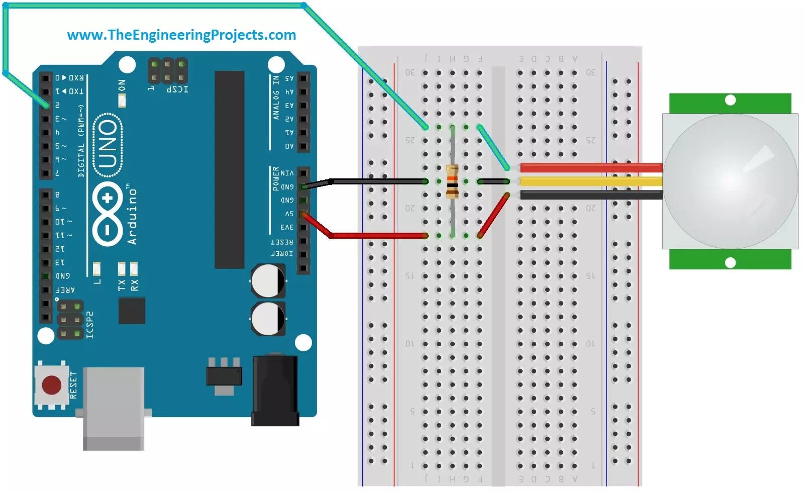
Hello friends, i hope you all are fine and enjoying. Today i am going to share a new project tutorial which is Interfacing PIR sensor with Arduino. First of all lets, have a little introduction about the basics and working of the PIR sensor. PIR sensors are in fact a Passive Infrared Sensor. PIR sensors are actually electronic sensors and they are used for motion detection. They are also used to detect the Infrared waves emitting from a particular object. You should also have a look at PIR Sensor Library for Proteus, using this library now you can easily simulate your PIR Sensor in Proteus software.

PIR sensors are widely used in motion detection projects now a days. Since my today's tutorial is about interfacing of PIR sensor with Arduino micro controller. Before going to that it is necessary that we should first understand the construction and working principle of PIR sensor. So i am going to divide my tutorial into different blocks and i will describe PIR sensor from its construction to practical applications. So first of all, lets see the construction and operating principle of PIR sensor.

Construction of PIR sensor

The construction of PIR sensor is very simple and easy to understand. In the bottom or you can say in the core of the PIR sensor we have a set of sensors which are made of pyro-electric materials. The properties of this material is that when this material is exposed to heat then, it generates energy. Different methods are used to to measure this energy generated by PIR sensor. On the top of the PIR sensor and above the internal sensors we have a small screen through which infrared radiations enters into sensor. When these radiations falls on the pyro-electric material then it generates energy. Generally the size of this sensor is very small and it is available in the form of thin film in market. Many other materials are also used in collaboration with pyro-electric material like galliam nitrite and cesium nitrate and all these materials take the form of an small integrated circuit.

Operating Principle of PIR sensor

The modern studies in the field of quantum physics tells us the fact each and every object when it is placed at a temperature above absolute zero, emits some energy in the form of heat and this heat energy is in fact the form of infrared radiations.  So an other question comes into mind that why our eyes can't see these waves? It is because that these waves have infrared wavelengths and his wavelength is invisible to human eyes. if you want to detect these waves then, you have to design a proper electronic circuit.

If you see closely the name of PIR sensor which is Passive Infrared Sensor. Passive elements are those elements that don't generate their own voltages or energy. They just only measures things. So we can say that this sensor is a passive infrared sensor and it doesn't generate anything by itself. It is only capable to measure the rediations emitted by other objects around it. It measures those raditions and do some desired calculations on them.

Interfacing of PIR Sensor with Arduino

PIR sensor have total 3 pins. The configuration of each pin is shown in the image given below:
  1. Pin#1 is of supply pin and it is used to connect +5 DC voltages.
  2. Pin#2 is of output pin and this pin is used to collect the output signal which is collected by PIR sensor.
  3. Pin#3 is marked as GND pin. This pin is used to provide ground to internal circuit of PIR sensor.
This whole configuration is also shown in the image given below:

The pin configuration of a PIR sensor is shown in the image given above. Since we have to interface the PIR sensor with Arduino micro controller. The image showing the interfacing of PIR sensor with Arduino is shown below as:

Interfacing Code

The code for interfacing Arduino micro controller with PIR sensor is given below as:
    #define pirPin 2

    int calibrationTime = 30;
    long unsigned int lowIn;
    long unsigned int pause = 5000;
    boolean lockLow = true;
    boolean takeLowTime;
    int PIRValue = 0;

    void setup()
    {
    Serial.begin(9600);
    pinMode(pirPin, INPUT);
    }

    void loop()
    {
    PIRSensor();
    }

    void PIRSensor()
    {
    if(digitalRead(pirPin) == HIGH)
    {
    if(lockLow)
    {
    PIRValue = 1;
    lockLow = false;
    Serial.println("Motion detected.");
    delay(50);
    }
    takeLowTime = true;
    }

    if(digitalRead(pirPin) == LOW)
    {

    if(takeLowTime){lowIn = millis();takeLowTime = false;}
    if(!lockLow && millis() - lowIn > pause)
    {
    PIRValue = 0;
    lockLow = true;
    Serial.println("Motion ended.");
    delay(50);
    }
    }
    }

Applications of PIR sensor

PIR sensors possess a no of applications and due to their low cost and much advanced features they are the main focus of different projects being made now a days. Some of their features and practical applications are listed below as:

  • They are able to sense the detection of people and other objects.
  • PIR sensors are also used in automatic lightening systems. In these type of systems, when a person comes in the vicinity of the sensor then, the lights are automatically turned ON.
  • They are used in outdoor lightening systems and also in some lift lobbies. You may have observed that when a person comes in front of the lift and if the doors are being closed then, the doors are opened again. This is all due to PIR sensors.
  • They are widely used in underground car parking system. At every parking position a PIR sensor is installed and when that position is vacant then, a green light glows over that place which means you can park here. And if that position has been occupied then, a red light will glow, representing that this position is already occupied.
  • PIR sensor is much compatible sensor and it has the ability to detect a particular motion and the output of this system is very sensitive and doesn't have any kind of noise in it.
Alright friends, that was all from today's post. If you have any questions, fell free to ask. Till next tutorial Take Care!!! :)  

Getting Started with Arduino Software

Hello friends, i hope you all are fine and enjoying in life. On a friends request, today i am going to share a new tutorial which is 'Getting Started with Arduino Software'. Previously i have uploaded a large no of project tutorials made on 555 timers and some MATLAB based Simulations. Now we are going to touch the next level and from now on we will work on mostly projects containing Arduino microcontroller.

To get started with Arduino microcontroller, we first need to learn the operating software of Arduino microcontroller. This tutorial is very informative and i will be using Arduino software 1.0.5. It is a very basic level software and very easy to learn. IF you have already worked on Arduino software then you don't need to go through it. This tutorial is only for begineers who have just bought the Arduino board and don't know wht to do with it. :)

This software is very user friendly. There are two versions of Arduino software available on theArduino official site. One isexe file which you need to install in your computer. While the second version is a simple rar file and you don't have to install the 'exe' file in your computer. You only copy the software at a particular folder and when you double click on it, it automatically starts to run. I will be explaining this tutorial in various parts. We will see all the options available in main menu and their functioning. Now i think we should move towards the actual working of the software and see how it woks and what are its control parameters.

Getting Started with Arduino Software

  • First of all copy the Arduino software folder where you can easily access it. For example, copy the folder on desktop of your computer.
  • Double click the folder and the next window will show all the sub-folders, which contains the libraries, hardware tools, references and all other things.
Note:
  • If you haven't bought your Arduino UNO yet, then you can buy it from this reliable source:

  • That window is also shown in the image given below:
  • The above image is showing all the sub-folders and and the Ardunio running application.
  • The above folder is showing the examples, drives, hardware, libraries, references, tools of the Arduino software.
  • When you will double click on the icon named as 'ardunio' then arduino software will start to run.
  • The next window which will open is shown in the image given below:
  • A very important thing to note is that when we write code in Arduino software window then, it is called a sketch.
  • This software automatically gives the name to the code, which you are going to write.
  • For example i have open the command window of Arduino software, then it saves every sketch with that particular date on which you are gonna write that sketch.
  • Since today is May 13, 2015 and this software has automatically saved the sketch with today's date.
  • Now coming towards menu bar, we have 5 options. I will explain all of them one by one.

File Menu Description

  • When you will single click the 'File' button then, a new window will open which is shown in the image given below:
  • This list is showing all the components which are encoded in 'File' button.
  • First option is 'new' and it will open a new window or new sketch. Next is 'open' and it will open the file or sketch which you will select and will try to open in Arduino software.
  • Next options are 'sketch book' and 'examples'. When you will click the examples button then it will open the Arduino libraries.
  • The Arduino libraries are shown in the inage given below:
  • This option will give all of the Arduino libraries. Arduino libraries are very useful in learning the basic code of Arduino.
  • For starters, you can go to the first option which is, '01. Basics' and it will give you some libraries of that projects which are very easy to understand.
  • You can simply click on any option and the code will automatically load into Arduino software.
  • Next options are 'close', 'save' , 'save as'. These options are very simple and every user is aware of these options.
  • Next option is 'upload'. It is very important option and it will load the particular code into Arduino sketch file.
  • Next option is of 'upload using programmer'. This option uploads the code into Arduino sketch which is written in some other software.
  • Next option is of 'page setup'. It gives you the options about alignment of the page and what size of sketch you want to keep.
  • Then comes the 'print' option and 'preferences'. When you will click on  'Preference' option then a new window will open and this window is shown in the image given below:
  • This window will open and it will be showing sketckbook location. where you wish to save all your sketches. We will give it location only once and afterwards it will automatically save the file at that particular location.
  • You can also select the language, in which Arduino sketch will be written and the font size can also be selected.
  • This option also gives the check flag. For example either you want to update or Arduino software version or you tends to use the existing software and many other options.
  • The last option in file menu is 'Quit'. By clicking on this option, Arduino software will close and the sketch which is running at that particular time will stop.

Edit Menu Description

  • After file menu then comes the 'Edit' menu. When you will single click on that icon then, a new window will open, containing all the options which are ancoded in 'Edit' menu.
  • That new window is shown in the image given below:
  • The first 2 options in Edit menu are 'Undo' and 'Redo'. If accidentally something goes wrong then, you will press undo button and problem will be eliminated.
  • Redo is the opposite of Undo option.
  • Next options are 'cut' and 'copy'. Nearly all users are aware of their functions.
  • The next option is 'copy from forum'. It will copy the sketch from a particular forum and will automatically save it into sketch window of Arduino software.
  • The very option is 'copy as HTML'. This option is used at that place where, you want to upload your sketch or code.
  • After writing you sketch, you just single click on this button and it will automatically convert the sketch language into HTML language and then you can easily upload it.
  • Next option is of 'paste'. You copy the sketch from some other folder and you can 'paste' it in this sketch menu. and you can easily compile it.
  • Next to paste option we have 'select all' option. Once you click on this option and the whole sketch will be selected. It's upto you either you want to copy it or whatever you want to do with the sketch.
  • The next option is very important which is 'comment/un-comment'. For those people who have done the coding before and are aware of the basics it is a simple options.
  • You bring the curser to any particular line and when you will first click on this button then, it will be commented. Which means physically this line is written in the code but logically it has no importance anymore.
  • to avail this particular line, you will again click on that particular line and then it will be 'un-comment'.
  • After un-commenting the line, now you can use it in code.
  • Next option is 'increase indent', by single clicking on this option you will observe that the width of blinking curser has been increased.
  • This is also very interesting feature in looking and also very beneficial for those people who have a little weak eye-side.
  • And if you are not comfortable with this feature then, don't worry we also have a secondary feature for it.
  • Then you will click on the next option named as 'Decrease indent' and it will automatically decrease the width of the curser and it will start to look like as before.
  • The next option is very interesting and it is to find anything within your sketch.
  • When you will click on that option, a new window will open which is shown in the image given below:
  • In this window you can see that we have no of options. First bar is of find.
  • Write in the first bar whats actually you want to find.
  • And if you think something has gone wrong and you want to make changes in your code, you just simply write that things in 'replace with' menu and the whole code will be changed accordingly.
  • Next options in the edit menu are 'find next' and 'find previous'. When you write something in find menu and the software finds it for you.
  • Now if you want to find what's written next to those lines, you just simply click on that options and it will show whats next to that thing in sketch.
  • Similarly you can also find whats written previous to that thing in our sketch.

Sketch Menu Description

  • After edit menu we have 'Sketch Menu' in the list. When you will click on that option then, a new window will open which is shown in the image given below:
  • In sketch menu we have total 4 options.
  • The first option is 'verify/compile'. If you have written a code and when you will click on this option, it will verify the whole code and it will compile it and if there is no error then, the sketch will start running.
  • Next option is of show sketch folder. By clicking on that icon, we will access that particular folder in which sketch has been saved.
  • Next option is of 'Add file' and if you want to add any particular file in your sketch, you just simply click on that option and that file will be added in your sketch.
  • The last option in sketch menu is very very important and it will enables you to 'import library' into your sketch.
  • When you will click on that button then, a new window will open which is shown in the image given below:
  • As you can see in the above shown image that in this software there are a large no of built in libraries and if you need to import any library in your sketch then, you can easily import it.

Tools Menu Description

  • The next option in the main menu is 'Tools'. In order to explore it you just simply click on it and a new window will open, which is shown in the image given below:
  • The very first option in 'sketch menu' is auto format and it will automatically give format to the sketch.
  • Next are Archive Sketch, Fix encoding and reload.
  • The most important option in tools menu is 'select board'. By clicking on this option a new window will open which is shown in the image given below:
  • You can see that we have a large no of options available here .
  • Its your choice to choose that Arduino board which you are going to use in your project.
  • Next option is of programmer and when you will click on this button then a new window will open, which is shown in the image given below:
  • You can see from here we can select that which type of programmer we are going to use in our project.
  • The default setting for this version is AVRISP, as shown in the above image.
  • The last option in tools menu is Burn Boothloader and the beauty of Arduino software is that it is capable to burn the code into its micro controller itself and no external burner is required for this purpose.

Help Menu Description

  • This is the last option in menu and when you will click on it then a new window will open which is shown in the image given below:
  • The help menu of Arduino software is very user friendly and it gives you ease to learn the software and to do something new.
  • You can see that the very first option is 'getting started' and when you will click this option it will guide you about the features of the Arduino software. How we are going to use it and what are its basics?
  • Other options are also related to help and are much informative, if you are writing a particular sketch and at any stage if you don't know what to do the next then, don't worry, Help will guide at every step.
  • Now coming towards next menu, which is below the main menu, it has 5 major icons, which are shown in the image given below:
  • In the above image you can see that, we have 5 major icons.
  • The icon numbered a '1' is of 'verify'. After writing the whole code, you just simply click on that icon and it will verify the whole sketch and if there is any error then it will also generate error.
  • The icon numbered as '2' is to upload the sketch into your micro controller.
  • The icon numbered as '3' is of 'New'. By clicking on that icon a new menu will open and it will allow you to write a new sketch in it.
  • The icon numbered as '4' is of 'open'. When you wish to open a existing file in your present code, you just simply click on that.
  • The icon numbered as '5' is of 'save'. When you have written a particular sketch, you simply click on that and that sketch will be saved automatically.
  • The last icon which is numbered s '6' is of serial monitor and after writing the whole code you just simply click on that and it will monitors the whole sketch thoroughly step by step.
  • if any error will present at any stage then it will generate error.

Alright friends, that was all from today's post. Today's tutorial was very informative so i conclude that you hve learned something new today. Till next tutorial Take Care !!! :)

Display ADC value on LCD using Arduino

Hello friends, hope you all are fine and having good life. In today's project, we will see how to display ADC value on LCD using Arduino in Proteus ISIS. Its quite a simple project in which we are gonna measure the voltage of ADC pins and then will display them over to LCD. The microcontroller I am using in this project is Arduino. The simulation is designed in Proteus ISIS. IF you are working on PIC Microcontroller then you should have a look at How to Display ADC value on LCD using PIC Microcontroller in Proteus ISIS.

Arduino has 10 bit ADC pins so whenever you apply voltage on these pins it will give you a value ranging from 0 to 1023 depending on the voltage provided. One can easily get this value using a simple function in Arduino analogRead(); but the real problem is to convert this analog value into the actual voltage present on the pin. Suppose you are using A0 pin of arduino and you are providing 3.3V over to this pin, now when you use this analoagRead() function then it will give you some value say 543, but you wanna know what's the actual voltage at this pin which is 3.3V so now converting this 543 to 3.3 is a bit tricky part. It's not difficult but involves a little calculations, which I am gonna cover today in detail. Before going any further, make sure you have already installed the Arduino Library For Proteus, if not then first do it because without this library you won't be able to use Arduino board in Proteus. So, let's get started with How to Display ADC value on LCD using Arduino.

Display ADC value on LCD using Arduino in Proteus ISIS

I have divided this tutorial on How to Display ADC value on LCD using Arduino in few steps, follow these steps carefully and if you get into some trouble then ask in comments and I will try my best to resolve them, all the materials are provided at the end of step 1 for download but I suggest that you design your own so that you do mistakes and learn from them. Moreover, you should also have a look at these Arduino Projects for Beginners. Anyways, let get started:

Step1: Circuit Designing in Proteus
  • First of all, I have designed a circuit in Proteus for Displaying ADC value on LCD using Arduino.
  • In this circuit, I have used two transformers which I have named as Potential Transformer and Current Transformer. I am supplying 220V to these transformers which is then converted into 5V.
  • I have set the turn ratio of these transformers such that they give maximum 5V at the output.
  • Now,rest of the circuit is simple, I have just connected the LCD with Arduino so that we could display these ADC value over to LCD.
Note:
  • Here's the circuit diagram of displaying ADC value on LCD using Arduino in Proteus ISIS:
  • You can download the Proteus Simulation and the Arduino hex file for Displaying ADC value on LCD using Arduino by clicking on below button:

Download Proteus Simulation and Arduino Hex File

  • It's quite simple and self explanatory. After designing the circuit diagram, now let's move to second step, which is code designing for Displaying ADC value on LCD using Arduino.
Step 2: Arduino Code Designing
  • Now copy the below code and paste it into Arduino software. Compile your code and get the Arduino hex file.
  • If you dont know How to get the hex file from Arduino then read Arduino Library for Proteus, I have explained it in detail there.
#include <LiquidCrystal.h>
#define NUM_SAMPLES 10

int sum = 0;
unsigned char sample_count = 0;
float voltage = 0.0;

LiquidCrystal lcd(12, 11, 5, 4, 3, 2);
const int PT = A0;
const int CT = A1;
float Cur;
float Vol;
float Power;

void setup() {
// set up the LCD's number of columns and rows:
lcd.begin(20, 4);
// Print a message to the LCD.
lcd.setCursor(6,1);
lcd.print("Welcome To");
lcd.setCursor(5,2);
lcd.print("Energy Meter");
//delay(5000);
lcd.clear();

Constants();
}

void loop() {
lcd.setCursor(0, 2);
ShowVoltage(9, 0, PT);
Vol = voltage;
ShowVoltage(9, 1, CT);
Cur = voltage;
Power = Vol * Cur;
lcd.setCursor(7,2);
lcd.print(Power);
}

void Constants()
{
lcd.setCursor(0,0);
lcd.print("Voltage: ");
lcd.setCursor(0,1);
lcd.print("Current: ");
lcd.setCursor(0,2);
lcd.print("Power: ");
lcd.setCursor(14,0);
lcd.print("V");
lcd.setCursor(14,1);
lcd.print("A");
lcd.setCursor(12,2);
lcd.print("W");
}

void ShowVoltage (int x,int y, unsigned int value)
{
while (sample_count < NUM_SAMPLES)
{
sum += analogRead(value);
sample_count++;
delay(10);
}

voltage = ((float)sum / (float)NUM_SAMPLES * 5.015) / 1024.0;
lcd.setCursor(x, y);
lcd.print(voltage);
sample_count = 0;
sum = 0;
}
  • The code is quite simple and self explanatory, the only difficulty is in ShowVoltage function. In this function, I have first taken an average of 10 ADC values and after that I have applied a simple formula over it and then it will start start giving the voltage value which I have simply displayed over the LCD.
  • Now everything's done, so Get your Hex File from Arduino Software and let's check the results whether it displayed ADC value on LCD using Arduino or not
Step 3: Result
  • We have designed the electronic circuit in Proteus and have also designed our code and uploaded the hex file in Arduino.
  • Now press start button and you will see something like this:
  • Now if you compare the voltages in voltmeter and on LCD, you can see they are exactly the same. You can check the value of variable resistor and the values in LCD will also change as the voltage in voltmeter change.
That's all for today, hope I have conveyed some knowledge today and now you can easily Display ADC value on LCD using Arduino. In the next post we will explore more Arduino features. Till then take care and have fun !!! :)

Installation of Arduino driver in Windows

In today's tutorial, we are going to see how to install Arduino driver in Windows. In the previous post, we have seen what is Arduino? and why is it so popular and whats its use? Now, afer getting the basic knowledge of Arduino, the next step you need to do is to install Arduino driver in your computer so that it got recognized by your computer as Arduino. If you don't install the Arduino driver in Wndows then you won't be able to program Arduino using Arduino software.

tis tutorial is quite basic and is for the newcomers, who wants to start working on the Arduino software, if you have already run some codes on your Arduino then its not for you. You can skip it. Anyways, It's quite easy and it won't take much time. So let's get started with it.

Installation of Arduino driver in Windows

  • First of all, download the Arduino software from Arduino official website. Download the most reent version of Arduino software, which is 1.6.3 while writing this post.
  • After downloading the software, now plug your Arduino USB into computer.
  • You will hear a small beep and Windows will try to intall the driver itself, but finally a yellow box will appear on the taskbar saying driver can't be installed.
Note:
  • If you haven't bought your Arduino UNO yet, then you can buy it from this reliable source:

  • So, now right click on your My Computer, open properties, then click on Device Manager and you will get a Window as shown in below figure:
  • Now click on Other devices which is encircled in the above figure and you will get a new element named as Unknown device. This Unknown device is actually our Arduino UNO on which we are going to install the driver.
  • Right click this Unknown device and then click on the Update Driver Software.
  • As you click on it, it will give you two options so click on the below one which says Browse My Computer For Driver Software.
  • On clicking it, you will get a Browse option, so now Browse in the Arduino software folder which you downloaded from the Arduino website and then open the drivers folder as shownin below figure and then hit NEXT button.
  • After clicking the Next button, it will start installing the driver as shown in below figure:
  • After the successful installation, it will show a window as shown below:
  • So, now we have succesfully installed the Arduino driver for Windows and if you check it has also assigned the Com Port to Arduino, which is COM16 in my case, as shown in above figure.
  • It will also be updated in the Device Manager as shown in below figure:
  • That's it, Arduino driver in Windows is succesfully installed and now you can use it and can upload the programming code in it, which we will see in the next post.
Hope it helped you in some way. Let's meet in the next post. Take care and have fun.

What is Arduino ?

Hello friends, today I am posting a very basic tutorial on what is Arduino ??? In this tutorial I am gonna explain the basics of Arduino for the beginners. I am writing this tutorial because I got a lot of requests from the engineers in which they ask questions like what is Arduino ? What's the difference between Arduino and PIC? How to use Arduino? etc etc. So I thought of writing this topic. It's a very basic tutorial so if you are already familiar with this board and know the answer of this simple question What is Arduino ??? then you can skip this tutorial but again you must read it once, may be you get something out of it. :)

I have posted a tutorial on Arduino Projects, in which I gave all the links of Arduino projects and tutorials posted on my blog, that's another reason for posting this tutorial. I am treating that Arduino Projects page as an ebook on Arduino so I am gonna post everything about Arduino as much as I can. And an ebook must have an intro chapter, which will be this one. So, let's get started.

What is Arduino ???

  • Arduino is nothing but a simple microcontroller board which is normally used in engineering projects where there's a need to automate something.
  • You can interface sensors with this board, can drive motors with this board, can plug switches in it etc.
  • In old ages ( not old enough :P ), people used simple switches for turning ON a bulb so like you click the switch and the bulb is ON, it was quite a simple circuit, after that relays are invented and then engineers used 555 timer circuits in order to turn ON lights on some specific time. But the 555 timer circuits are quite big in size, so finally engineers discovered Microcontrollers in which there are simple OUTPUT and INPUT pins, so now if you want to turn on light at some certain time then you just simply plug the blub on output pin of microcontroller and then do some programming and add a timer to automatically turn on the bulb.
  • So, the benefit of microcontroller is the circuit is quite simple and small in size.Moreover, its flexible, suppose you want to change the time of turning ON bulb then what you need to do is simply change the coding and it will be changed, but in 555 timer circuits you need to change the components in order to do so.
  • Now, we know the use of microcontroller and also their benefit but thing is what is Arduino ??? In microcontrollers like PIC or Atmel, there's a small drawback.
  • Suppose you want to work on PIC then you have to first design its basic circuit also need to design a power circuit to supply power to it and after that in order to upload the code in it, you have to buy a programmer/ burner as well. So, first of all you need to write the code for PIC Microcontroller and after that you need to upload code in it using a programmer and then plce PIC microcontroller back into the circuit and test, which is quite lengthy plus also got hectic when you are working on some project because you have to test code again and again.
  • By the way, now advance programmers like PICkit2 and PICkit3 can be plugged on board but still you have to design the basic circuit so coming to bottom line, in order to do project with PIC or Atmel microcontroller you have to do soldering etc.
  • But that's not the case with Arduino Board, Arduino has built in programmer and the basic circuit in it. So what you need to do is simply plug in Arduino with your computer via usb cable, get its software and start uploading code and also start testing.
  • So, you don't need to plug unplug or do anything, simply upload the code and test. Moreover, it also has some very efficient tools using which you can test your output as well quite easily. Arduino board also has the pins on which you can simply plug your devices and can turn them ON or OFF. So, hats off to Arduino team for providing us a simple board which has everything on it.
  • Another advantage of Arduino is that, because of its popularity all the electronic components also have the Arduino libraries which are free and using them you can operate that electronic component quite easily with Arduino. Its open source and hence its developing day by day.

Types of Arduino Boards

  • There's a long range of Arduino boards available online, the basic Arduino board is named as Arduino UNO which is most widely used in projects.
  • Arduino UNO has total 13 digital pins and 6 analog pins which are used for connecting sensors with them.
  • Suppose you have a project in which you want to interface 30 sensors, then what you need to do ?? Now you need to buy another Arduino board named as Arduino Mega 2560. This board has around 70 pins on it which can be used as output or input and hence you can plug your sensors quite easily.
  • Moreover, Arduino have also developed different shields like Arduino Ethernet shield. Using this shield you can provide internet access via Ethernet to your project.
  • Then they have Arduino Wifi shield which is used for providing Wifi access to your project.
  • They have also developed Arduino GSM shield for GSM or GPRS purposes, in short there's a wide range of Arduino boards available online.
  • So which Arduino board you need to buy depends on the requirements of your project.

How to use Arduino ??

  • Now I think you have got the basic idea of what is Arduino ? and why is it so popular ? So now lets have a look at how to use Arduino.
  • When you order for your Arduino board, you will get a package similar to the image below:
  • Along with this box, you will also have the USB cable, now take your Arduino board out of this box and plug the cable in it, connect the Arduino with your computer and you are ready to start working on it.
  • In order to connect Arduino with your computer you have to install the Arduino drivers in Windows.
That's all for today, hope I have conveyed some knowledge and you now know the basics of Arduino i.e. what is Arduino ? and why to use Arduino.

Arduino Projects

Hello friends, I hope you all are fine and having fun with your lives.Today I am not gonna post a new topic or tutorial, instead I am going to arrange all my Arduino Projects and tutorials in this post, as its better to have all of them in one place. I recently posted a PIC Microcontroller Projects post and it was highly appreciated by the followers so I thought to do the same with Arduino as well because I have posted more Arduino projects as compared to PIC Microcontroller. I will post all the Arduino Projects & Tutorials links below in sequence i.e. from easy to pro level so if you are a new user and want to get command over Arduino projects then read all of them one by one. Moreover, I will also keep on updating this post whenever I am gonna add any new Arduino Project or Tutorial. If you feel problem in any of the below tutorials then ask in comments and I will try my level best to solve your queries. As I always say learning is all about practise and patience. So while doing Arduino Projects, you have to be patient and practical, don't just read these articles, always test these arduino Projects and tutorials. Because when you practically perform some project then you will do mistakes and get the chance to learn from them. You should also have a look at these Arduino Project for Beginners.

Arduino Introductory Tutorials

If you have already run your first code on Arduino then you can skip this section. This section is for the beginners who don't know anything about Arduino. I have explained in detail how to get started with Arduino board and at the end of this section, you will have the complete idea of how Arduino works and how to program arduino. You must visit the Official Arduino Site and join their forum because they have posted a lot of Arduino Projects there.
Arduino Tutorials - Basics
What is Arduino ??? Here's our first tutorial where I have explained the very basics of Arduino i.e. what is Arduino and how to use it? Arduino Vs Raspberry Pi In this tutorial, I have explained the difference between Arduino and Raspberry Pi in detail. I have discussed their Pros and Cons in detail. So, give it a try if you are confused in choosing between them. Installation of Arduino driver in Windows When you run your Arduino board for the first time on your laptop or computer then you have to install Arduino drivers. Without installing Arduino drivers, you can't upload your Arduino code in Arduino board. How to get Hex File from Arduino ??? When you are using Proteus software for simulating your Arduino Projects then its necessary to upload Hex File in it. How to Upload Bootloader in Atmega328 ??? Arduino UNO board uses Atmega328 microcontroller so if you wanna use Arduino as a programmer and want to upload code in your Atmega328 microcontroller then you need to upload the Bootloader in it, which is explained in this post. Getting Started With Arduino Software Now I suppose that you have installed the Arduino drivers in previous tutorial so now you are ready to get an overview of Arduino software. Getting Started with Arduino Programming In this tutorial, I have mentioned basic concepts of Arduino Programming and have also written a very small code to get you familiar with Arduino Programming. How to Reset Arduino Programmatically ??? In some Arduino projects we have to reset the Arduino board programmatically instead of manually so I have shared this small trick in this tutorial.
Arduino Boards - Introduction
Here I am gonna give you the basic Introduction of all Arduino boards one by one. I would suggest you to at least read that one, on which you are working. I have shared detailed Pinouts, Pin Description and features. Introduction to Arduino UNO In this tutorial, I have discussed the detailed overview of Arduino UNO alongwith its Pinout. That's the most commonly used Arduino Board. Introduction to Arduino NANO In this tutorial, I have discussed the detailed overview of Arduino NANO alongwith its Pinout. It is used because of its small size. Introduction to Arduino Pro Mini In this tutorial, I have discussed the detailed overview of Arduino Pro Mini alongwith its Pinout and design. That's the smallest Arduino Microcontroller board. Introduction to Arduino Mega 2560 In this tutorial, I have discussed the detailed overview of Arduino Mega 2560 alongwith its Pinout. It's famous because of its large number of I/O Pins. Introduction to Arduino DUE In this tutorial, I have discussed the detailed overview of Arduino DUE alongwith its Pinout. If you are working on it, then must read that tutorial. Introduction to Arduino Lilypad In this tutorial, I have discussed the detailed overview of Arduino Lilypad alongwith its Pinout. That's the most stylish Arduino board. :) Introduction to ATmega328 Atmega328 is the Microcontroller used in Arduino UNO, NANO and Pro Mini. So I would suggest you to read about it as well.
Arduino Libraries

I always advise students to work on simulation first. If you are working on Arduino Projects, then Proteus is the best software for simulations. You should have a look at these New Proteus Libraries for Engineering Students, but here I have only posted Arduino Libraries, which are free to download directly from our site.

[TEPImg17]Arduino Library For Proteus Using this Arduino Library for Proteus, you can easily simulate your Arduino boards in Proteus software and can easily design any Arduino Project in Proteus. This Library includes five Arduino boards. Arduino UNO PCB Design for Proteus ARES In this post, I have shared the PCB design of Arduino UNO board in Proteus ARES, which you can easily download from this post and then can import it in your Proteus ISIS software. Arduino Lilypad Library For Proteus This Library includes the Arduino Lilypad Library for Proteus. Using this library you can easily simulate your Arduino Lilypad board in Proteus ISIS. This Library contains only the Arduino Lilypad board.

Arduino Projects

Now you know the basics of Arduino board and also have the idea how to use arduino software and write code in it. So, now let's get started with Arduino Projects. I have divided this section in several sections depending on which Arduino board I am using in the project. These arduino projects are designed by our team and are designed after quite a lot of efforts but are free here for the readers, so if you wanna share them then do mention us. :)
Arduino Tutorials - Basic
These are few basic Arduino Tutorials, which are very essential for you, if you are a beginner. So, follow them one by one and also design their basic Proteus simulations so that you learn more. So, let's get started with them:
Arduino UNO Projects
  • Circuit Designing of LCD With Arduino in Proteus .? Now you have understood the basics of Arduino board and have also installed the Proteus Library of Arduino board so now you are ready for designing small Arduino Projects.In this tutorial, I have interfaced LCD with Arduino baord and I have done it in Proteus ISIS software.
  • Interfacing of Keypad with Arduino in Proteus ISIS.? After the interfacing of LCD, next thing you should interface with Arduino is Keypad which is done in this tutorial. So, in this tutorial I have interfaced the Keypad with Arduino and then have shown the keypad characters on LCD.
  • Display ADC value on LCD using Arduino in Proteus ? Now that we have interfaced the LCD with Arduino so now its time to display something on it. So, for that purpose I have displyed the ADC value of Arduino analog Pin on LCD. This Project is also designed in Proteus ISIS software.
  • Ultrasonic Sensor with Arduino Simulation in Proteus ? In this tutorial, I have interfaced Ultrasonic Sensor with Arduino board in Proteus ISIS software.Remember, we have installed the Ultrasonic Sensor Library for Proteus in the previous section. So, using that Library now I have interfaced this Utrasonic Sensor with Arduino Board.
  • Interfacing of Ultrasonic Sensor with Arduino ? In this tutorial, I have interfaced the Ultrasonic Sensor with Arduino in hardware. I have designed a circuit on Vero Board and then tested it. Distance of obstacle from Ultrasonic Sensor is displayed on LCD in cm.
  • Interfacing of Multiple Ultrasonic Sensors with Arduino ? In the previous tutorial, I have interfaced single ultrasonic sensor with Arduino but in this post I have interfaced multiple ultrasonic sensors with Arduino board and displayed their values via Serial Terminal in Proteus ISIS.
  • Interfacing of Temperature Sensor 18B20 with Arduino ? In this project, I have interfaced the Temperature Sensor 18B20 with Arduino and displayed the atmospheric temperature on LCD. Its a one wire Temperature sensor and gives quite accurate value.
  • How to use Temperature Sensor 18B20 with Arduino in Proteus ISIS ? In this project, I have interfaced the Temperature Sensor 18B20 with Arduino and displayed the atmospheric temperature on LCD. Its a one wire Temperature sensor and gives quite accurate value. This Arduino Project is designed in Proteus ISIS.
  • Interfacing of Temperature Sensor LM35 with Arduino ? In this project, I have interfaced the Temperature Sensor LM35 with Arduino and displayed the atmospheric temperature on LCD. Its an analog Temperature sensor and gives quite accurate value. This Arduino Project is designed in Proteus ISIS.
  • Interfacing of Seven Segment With Arduino in Proteus ? In this project, I have interfaced the Seven Segment Display with Arduino and displayed different alphanumeric value on this Seven Segment Display. This Project is also designed in Proteus ISIS software.
  • Interfacing PIR Sensor with Arduino ? In this project, I have interfaced the PIR Sensor with Arduino. I have used the PIR Sensor Library for Proteus in order to design this Arduino Project. PIR Sensor is used for motion detection and it displayed the results on LCD.
  • Interfacing of Flame Sensor with Arduino ? In this project, I have interfaced the Flame Sensor with Arduino and used it for Fire Detection. Its an analog Sensor used for Flame detection, on the basis of which we decides whether there's Fire or not. This Arduino Project is designed in Proteus ISIS.
  • Interfacing of NRF24L01 with Arduino ? In this project, I have interfaced the NRF24L01 RF module with Arduino and designed two nodes among which data is transferred wirelessly. First Node acted as a Transmitter while the second node acted as a Receiver. This was one of the toughest Arduino Projects.
  • NRF24L01+ with Arduino - Response Timed Out ? While using NR24L01, I have encountered a problem named as Response timed Out and in this post I have shown a small trick on How to remove this error and after that it worked perfectly fine. If you are working on NRF24L01 then you must check it out.
  • Interfacing of RFID RC522 with Arduino ? In this project, I have interfacedRFID RC522 with Arduino and detected different RFID cards with this RFID module. I have designed it on hardware as this sensor is not yet available in Proteus ISIS.
  • Arduino Bluetooth communication using HC-05 ? In this project, I have done a Bluetooth communication using HC-05 bluetooth module. This bluetooth module was connected with Arduino board and then data is sent from Arduino to mobile via Bluetooth.
  • Control Servo Motor with Arduino in Proteus ? In this project, I have controlled the Servo Motor with Arduino in Proteus ISIS. Its quite a quick tutorial but is very hepful if you are working on Servo Motors. Servo Motors are controlled via single Pin and are used in Arduino Projects where accuracy is required.
  • Traffic Signal Control Project Using Arduino ? Its a small Arduino Project which is normally designed by students in their first or second semesters. In this Project I have modeled a complete Traffic Signal Control. This Project is designed in Proteus ISIS.
  • Scrolling Text on LED Matrix 8×8 using Arduino in Proteus ISIS ? In this project, I have interfaced LED Matrix 8x8 with Arduino and then I have displayed a scrolling text on these LED Matrices. This Project is designed in Proteus ISIS.
  • Intelligent Energy Saving System ? In this Arduino project, I have designed an Intelligent Energy Saving System. In this project, the system automatically turns ON or OFF the lights & Fans depending on presence of person in the room. Its YouTube video is also given in this tutorial.
  • USB Communication between Android and Arduino ? In this project, I have communicated between Arduino & Android via USB. The Android phone is connected with Arduino via USB cable and then data is sent from Android phone to Arduino via USB.
  • Home Automation Project using XBee & Arduino ? In this project, I have designed a complete Home Automation Project in which the Loads of a room are controlled via remote. For wireless communcation between remote and the loads I have used XBee module.
  • GSM Based Home Security System ? In this project, I have designed a Home Security System and used seven sensors for security purposes and when any of those sensors gave warning then a tet message is sent over to user's mobile phone.
GSM Module (SIM900) With Arduino: EasyVR Shield With Arduino:
  • Voice Recognition Project Using EasyVR Shield ? Its a series of tutorials on EasyVR shield and its the first tutorial in this series. In this tutorial, I have given an overview of the Project named as Voice Recognition Project using EasyVR Shield.
  • Getting Started with EasyVR Commander ? Its the second tutorial in the series of EasyVR Shield. In this tutorial, I have explained how to get started with EasyVR Commander which is a software for uploading voices in EasyVR shield.
  • Interfacing of EasyVR Shield with Arduino UNO ? Its the third tutorial in the series of EasyVR Shield. In this tutorial, I have interfaced EasyVR shield with Arduino UNO and then recognized the commands said by the user. It's quite an interesting Arduino Project.
  • How to solve Training Error: Recognition Failed in EasyVR ? Its the fourth tutorial in the series of EasyVR Shield. While working on EasyVR shield I encountered this error so I thought to share its solution with your guys. So, if you encountered such error then check this tutorial.
XBee Module With Arduino: Pixy Camera With Arduino: Motor Interfacing With Arduino:
Arduino Wifi Projects
Arduino YUN Projects
These Arduino Projects and tutorials I have yet posted on my blog, I hope these will help you in some way. I will keep on updating this post with more Arduino Projects. So stay tuned and remember me in your prayers. Take care!!! :) [/vc_column_text][/vc_column][vc_column][/vc_column][vc_column][/vc_column][/vc_row]
Syed Zain Nasir

I am Syed Zain Nasir, the founder of <a href=https://www.TheEngineeringProjects.com/>The Engineering Projects</a> (TEP). I am a programmer since 2009 before that I just search things, make small projects and now I am sharing my knowledge through this platform.I also work as a freelancer and did many projects related to programming and electrical circuitry. <a href=https://plus.google.com/+SyedZainNasir/>My Google Profile+</a>

Share
Published by
Syed Zain Nasir