Genuino Library for Proteus

Hello friends, hope you all are fine and having fun with your lives. Today, I am going to share a new Genuino Library for Proteus. Genuino boards are just the same as Arduino boards but with slight difference of color and shape. I have already posted a tutorial on Arduino Library for Proteus in which I have explained how to download the Arduino Library and use it in Proteus. Today, I am going to post a similar library but for Genuino boards. Their functionality is exactly the same as the Arduino Library but they have better look and Genuino Color.

II hope you are gonna like this library as well. Other bloggers are welcome to share this library with their reader but do mention our link in creator section, we will be really obliged. Now, let's start with the Genuino Library for Proteus.

Genuino Library for Proteus

  • First of all, download the Genuino Library for Proteus from the below button:
Genuino Library for Proteus

  • In the above link, you will get an rar file which will have two files, named as:
    • GenuinoTEP.LIB
    • GenuinoTEP.IDX
  • Now place these two files in the Library folder of your Proteus software.
Note:
  • Now start your Proteus software and go to Component searching section and search for GenuinoTEP as shown in the below figure:
  • Now place them in your Proteus work space and they will look like as shown in below figure:
  • In the above figure, five of these genuino boards are visible. The sixth board is Arduino Mega1280, which is similar to Arduino Mega 2560 in shape so that's why I have omitted it in the above image.
  • Now you can design any of your project on Genuino board quite easily in Proteus using this Genuino Library for Proteus.
  • In order to upload the code in any of these boards you need to double click it to open its properties.
  • For example I double click the Arduino UNO baord then the Properties panel will look like as shown in below figure:
  • In the above figure, you can see a section named Program file, that's where you are gonna browse your hex file.
  • You should read How to get Hex file from Arduino, if you don't know already.
  • So, get the hex file and upload here and your Genuino board will get active.
  • In the below video, I have explained in detail How to use this Genuino board in Proteus and have already tested the blink example.

That's all for today, I hope you will enjoy this Genuino Library for Proteus. Let me know your suggestions about this library. Have fun !!! :)

Arduino Bluetooth Communication using HC05

Hello friends, hope you all are fine and having fun with your lives. Today, I am going to share a new project in which we are gonna do Arduino Bluetooth communication. The Bluetooth module I have used for this project is HC-05, which is a serial Bluetooth module. We can quite easily perform the Bluetooth communication with this module using Arduino board. I have worked on many projects in which I have to send the data from sensors to my computer via Bluetooth. So, in such projects I normally use this Bluetooth module which is connected with the sensors and then Arduino gets the data from these sensors and then send this data to computer via Bluetooth module. In this project, I have used Arduino board but you can use PIC Microcontroller or 8051 Microcontroller as well. Because they both have the Serial pins on them.

Note:

Before reading any further, I think you must have a look at the below post from where you can download the Bluetooth Library for Proteus, using this library you can easily simulate HC-05 or , HC-06 in Proteus software:

I have also done Bluetooth communication with Android mobiles. In these projects I have sent the data from this Bluetooth module to Android mobiles but in such projects I have also designed Bluetooth app on which this data is received. Anyways, that's a topic of another tutorial. Today, I am gonna connect this Bluetooth module with Arduino board and then will send some data to my computer using Bluetooth. So, let's get started with Arduino Bluetooth communication using HC-05 module.

Arduino Bluetooth Communication using HC-05

  • First of all, what you need to do is to buy the Arduino board. I have designed this project using Arduino UNO board but you can buy any of the Arduino Microcontroller board.
  • Next thing you are gonna need is Bluetooth module which is HC-05. But this tutorial will also work for HC-06 or HC-07.
  • Now if you have seen HC-05 then the pins are written on it so connect them with your Arduino board as shown below:
  • This pin configuration is also shown in the below figure:
  • Now that you have connected your Arduino board with the Bluetooth module HC-05 so you are ready to do the Arduino Bluetooth communication.
  • Now upload the below code in your Arduino board:
#include <SoftwareSerial.h>

SoftwareSerial mySerial(2, 3);

void setup()
{
  Serial.begin(9600);
  mySerial.begin(9600);
}

void loop() 
{
  if (mySerial.available())
    Serial.write(mySerial.read());
  if (Serial.available())
    mySerial.write(Serial.read());
}
  • Its a simple software serial code in which we are sending data from our Serial terminal to Bluetooth means whatever you write in your serial terminal will be sent over to Bluetooth and whatever you receive on your Bluetooth will be shown in serial terminal.
  • Now, download this Serial monitor software, I have designed this software and its quite simple one. You can use any other serial monitor like Virtual Terminal in Proteus or Hyper Terminal in Windows XP.
  • We are gonna use this software to get the data on our computer via Bluetooth and you computer must have the Bluetooth in your computer. :P
  • So, download this software by clicking the below button and you can read more about it Microsoft Visual Basic 2010 - Com Port Tutorial.

Download Serial Terminal

  • Now turn on your Arduino and search for the Bluetooth device in your Bluetooth settings and paired with it as shown in below figure.
  • The default pin code for HC-05 is 1234.
  • Now you can see I have paired the HC-05 device.
  • Now, open this software and connect with the COM port of your Bluetooth device.
  • The Bluetooth device generates two COM ports in my case it generated COM11 and COM12 but COM11 worked.
  • So, I connected with COM11 and then whatever I entered in my software is shown on the serial monitor of my Arduino and whatever I entered in the Serial monitor of Arduino is shown in the serial terminal software.
  • Its quite simple and you can do it quite easily.

So, that's all for today and I hope you are gonna make it work in the single attempt. If still having problems then ask in comments and I will resolve them. So, today we have done Arduino Bluetooth communication using HC-05 module.

Automatically Connect with Wifi SSID using Arduino YUN

Hello Friends, hope you all are fine and having fun. In today tutorial i am going to elaborate How to Automatically Connect with Wifi SSID using Arduino YUN. If you recall one of my previous tutorials named Getting started with Arduino YUN , in which i gave a brief introduction about Arduino YUN, its working and features. In that tutorial, I have explained How to connect Arduino YUN with Wifi manually. A little problem encounters while connecting Arduino manually to available wifi networks that if wifi connection drops then, then Arduino will also disconnect automatically and if wifi connection is energized again, it will still remain disconnected unless you reconnect it by yourself. This thing has very serious drawbacks in industrial projects, where data is continuously uploaded through multiple servers and if at any stage connection drops and Arduino stops working then, this thing leads to drastic outcomes.

So there is serious need to design an algorithm in which Arduino automatically connects to the available wifi connections and should enables the server to upload data through it. This whole process is a bit lengthy and much complicated. So, i will elaborate all this in the coming tutorials. In today's tutorial i am going to restrict myself only How to get Available wifi SSID using Arduino YUN. First of all lets recall the basics of Arduino YUN. Arduino YUN has 2 micro processors embedded on the same board. First is the Arduino microprocessor and the second is Atheros micro processor. Atheros supports Linux server (commonly used in Apple computers). With both these on-board micro processors, we can do anything we want to do. The beauty of Arduino board is that it has built in wifi, Ethernet port, USB host and SD card slot. We can also upload data into Arduino through wifi without physically connecting it with computer. That's why Arduino boards are the most widely used micro processors now a days, and are able to handle multitasking industrial projects. Above was a little introduction about Arduino YUN and now lets get started with our today's tutorial.

Automatically Connect with Wifi SSID using Arduino YUN

  • First of all open the Arduino softeare. On toolbar click on the icon named "Tools" and a new window will open. Then go to the option "Board" and from the next opened window select the board "Arduino YUN".
NOTE:
  • Remember you must download the Arduino software version 1.5.5 + instead of 1.0.3 because Arduino sketches will be only compiled in 1.5.5 version which is specifically designed for Arduino YUN.
  • After selecting the board, you will load the given below code into Arduino Board.
#include <Process.h>
#include <FileIO.h>

String ESSID = "TEP";            
String Pass = "Pakistan";            
String Encrypt = "psk2";
          
void setup() {

Serial.begin(9600);  
delay(5000);    
FileSystem.begin();
delay(5000);
Bridge.begin();  
delay(5000); 
}

void loop() {
// put your main code here, to run repeatedly:
    WifiAuthentication();
}


void WifiAuthentication()
{
      uploadScript();
      delay(1000);
      runScript();
      delay(20000);
}
void uploadScript() 
{
  
      File script = FileSystem.open("/tmp/setupwifi.sh", FILE_WRITE);   
      script.print("#!/bin/sh\n");
      script.print("/sbin/uci set  network.lan=interface\n");
      script.print("/sbin/uci set  network.lan.proto=dhcp\n");
      script.print("/sbin/uci delete  network.lan.ipaddr\n");
      script.print("/sbin/uci delete  network.lan.netmask\n");
      script.print("/sbin/uci set wireless.@wifi-iface[0].mode=sta\n");
      script.print("/sbin/uci set wireless.@wifi-iface[0].ssid=" + ESSID + "\n"); 
      script.print("/sbin/uci set wireless.@wifi-iface[0].encryption=" + Encrypt + "\n");
      script.print("/sbin/uci set wireless.@wifi-iface[0].key=" + Pass + "\n");
      script.print("/sbin/uci commit wireless; /sbin/wifi\n");
      script.print("/etc/init.d/network  restart\n");
      script.close();  
      Process chmod;
      chmod.begin("chmod");      
      chmod.addParameter("755");  
      chmod.addParameter("/tmp/setupwifi.sh");
      chmod.run();
}

void runScript() 
{
      Process myscript;
      myscript.begin("/tmp/setupwifi.sh");
      myscript.run();
      Serial.println("Connected");
}
  • The above given code is a bit complicated and it consists of many steps. Now i am going to show all the steps through a block diagram and then i will try to explain every step one by one.
  • Using this code, the Arduino YUN board will automatically connected to the available SSID which is in our case is TEP. So you can give any other SSID there and it will connect to that one.
  • In the above block diagram, you can see that first of all Initialize Serial Port. When you will connect Arduino YUN with your computer through cable or as i described earlier that Arduino YUN also have built-in wifi so you can also connect Arduino YUN with computer through wifi.
  • Then you will load the code to Initialize Serial Port, which is the first step and also shown in the above block diagram.
  • In this project we have kept Baud rate of Arduino YUN 9600.
  • The next step in the block diagram is to 'Initialize File System' . In this step we will load 'File System' into our code as viewed in the code image given above.
  • Now in the next step we have to initialize the Arduino YUN Bridge. The block diagram representing the internal structure of Arduino YUN is shown in the image below:
  •  As i stated earlier in the beginning of the tutorial that Arduino YUN has 2 on-board micro processors and Arduino YUN is the intermediate source who performs communication between both micro processors.
  • The Bridge library facilitates communication between the two processors, giving Arduino sketches the ability to run shell scripts, communicate with network interfaces, and receive information from the AR 9331 processor.
  • The USB Host is connected to the ATmega 32u4, while the all external interferences(like Wifi, Ethernet, SD card) are connected to Linux micro processor.
  • The beauty of this board is that Bridge libraries also enables the Arduino micr processor ATmega to communicate with the other interferences, which are also connected with Linux microprocessor.
  • When bridge has been activated then, Arduino YUN enables its wifi and search for the nearby available wifi connections.
  • When it will get some available wifi connections in its surrounding then, from its algorithm, Arduino YUN will get the SSID from that available wifi connections.
  • The next thing which we have implemented in the code is to get SSID String. It is a built in function and also available in Arduino libraries that if it gets any available wifi connection near it, then it automatically gets strings from those connections.
  • When Arduino has searched for all the available wifi connections near it and after getting the SSID of available wifi connections, it sends all these SSID to serial port of Arduino YUN board.
  • After that Arduino YUN will automatically connect to that wifi connection whose SSID matches with the given SSID.
  • Now the end step is very important and it distinguishes Arduino YUN from all other Arduino boards, which is, After sending data to serial port it again starts the loop and got o step #4 and it again starts to search for available wifi networks.
  • This phenomenon can also be verified from the above shown block diagram.
  • At any stage, if wifi connection drops then the loop will again start and will search for available wifi connections, get their SSID and it will send these SSID to serial port and it will rehabilitate the connection within no time and no problem will occur at any stage of data execution.
Alright friends, that was all from today's post. It is a very basic and very important post and we have seen How to Automatically Connect with Wifi SSID using Arduino YUN. I hope you have learned something new in today's post. If you have any problem in understanding any step of this tutorial then, you can ask in the comments and i will try my best to resolve the issue. Follow us to get the codes and simulations straight in your inbox. For more tutorial and projects, stay tuned and until next tutorial Take Care !!! :)

Electronic Quiz Project with 8051 Microcontroller

Hello friends, hope you all are fine. In today's project, we are gonna design Electronic Quiz Project with 8051 Microcontroller. I have done this project recently in which we need to design a quiz project game using 8051 Microcontroller. It was quite a big project and we have to work quite hard to make it done. In this project we have used many components on which I have already post tutorials so that you guys first get introduction to those components. So, first of all you should read Interfacing of LCD with 8051 Microcontroller, after that you must check Interfacing of Keypad with 8051 Microcontroller and finally get your hands on Serial communication with 8051 Microcontroller. These tutorial are must to read because these are all gonna use in today's project.

So, before going in details of this project, let me first tell you that its not free because we have done quite a lot of work in designing it so it will be of $20. We have placed quite a small amount as mostly it will be downloaded by the engineers students.You can download it by clicking the above button, but before buying it must read the details and also check the video posted at the end of this tutorial so that you know what you are buying. So, let's get started with the details of this project.

Overview of Electronics Quiz Project

  • Let's first have some overview of Electronic Quiz Project with 8051 Microcontroller.
  • In this project, I have designed a quiz game which has two modes in total named as:
    • Single Player.Mode
    • Two player Mode
  • In the start of this project, using keypad you have to select the Mode i.e. you wanna start Single player Mode or Two Player Mode.
  • Now let's check the details of each mode seperately:
Single Player Mode
  • When you select the single player mode then only one player can answer the questions.
  • In order to answer the questions, you have to use keypad.
  • The questions will be displayed on LCD.
  • The questions are in the form of MCQs so ti will have four options.
  • So,whenever the question is displayed on LCD, you need to use keypad to select the correct answer.
  • Rite now, I have added 6 questions in its database, which you can change easily or can also add more questions.
  • In single run, it will ask 3 random questions from the user and will get the answers.
  • For each correct answer, it will add the 5 marks and for each wrong answer it will subtract 2 marks.
  • After attempting all the 3 questions, it will display the final marks on the LCD screen.
  • Now you need to press any button to restart the system.
  • Below is given the Block diagram for the algorithm of Single Player Mode.
Two Player Mode
  • In two player Mode, there will be a competition between two players, in which first player will reply the question using keypad while the second player will reply the question using Keyboard which will come to the system via Serial port.
  • The question will be displayed on the LCD and the laptop at the same time, the question coming to laptop is via Serial port so you need to open some Serial Monitoring if you have designed it in hardware while in Proteus I have used Virtual Terminal to display the question.
  • Now after the question is displayed, system will wait for the response from both the players.
  • Now among the two players, who will press the 0 button first will be able to answer the question.
  • If he gave the correct answer, then 5 marks will be added in his total marks and if he gave wrong answer then 3 marks will be deducted.
  • IF the selected person given the wrong answer then the system will move to second user and will ask for the answer from him.
  • Now if the second user give the correct answer then 5 marks will be added in his marks and he give wrong answer then no marks will be deducted.
  • Total of three marks will be asked and at the end of these questions, marks of both players will be displayed and who got the maximum marks will be considered as a winner.
  • Now if you press any key, the system will restart.
  • The complete block diagram for the algorithm of two player mode is shown below:
Components Used
I have used below components in designing this project:
  • 8051 Microcontroller (AT89C51)
  • Keypad
  • LCD (20 x 4)
  • Serial Communication
  • Laptop or PC
So, now let's have a look at the Proteus Simulation and working of Electronic Quiz Project with 8051 Microcontroller.

Electronic Quiz Project with 8051 Microcontroller

  • So, now we have the detailed overview of Electronic quiz project with 8051 microcontroller. Let's design its Proteus Simulation.
  • Design a circuit in Proteus as shown in below figure:
 
Programming Code
  • I have designed the programming code in Keil uvision 3 for Electronic Quiz Project with 8051 Microcontroller.
  • I am not gonna share the complete code here because its not free but you can buy it quite easily by clicking the below button for just $20.
  • But I am gonna explain the code in chunks so that you get some idea How I am doing this Electronic quiz project with 8051 Microcontroller.
  • First of all let's have look at lcd code. In my previous post I was writing character by character on LCD because it was quite a small project, but now I have to print quite a lot of string so that's why I have written a function to which you can give any string and it will print it on LCD. The function is as follow:
void writeline_lcd(char line[])
{
   		int i;
   		for(i=0;i<strlen(line);i++)
   		{ writedata(line[i]); } //write to lcd
   
}
  • Using this function, you can easily write complete string on LCD.
  • Next in order to send data to Serial Port I have used the below function:
void writeline_serial(char line1[])
{  
   int i;
   EA = 0; ES = 0;
   for(i=0;i<strlen(line1);i++)
   { SendByteSerially(line1[i]); } // SEND DATA TO PC 
   EA = 1; ES = 1;
}
  • For storing the questions I have used the below function:
void Ask_Question(void)
{
	int q = 13;
	writecmd(0x01);
	
	//randomize question
	while(!(q<7 & q>-1))
	{
		q = (TL1%6);
		if(q1==1 & q==1)  { q = 6; }
		if(q2==1 & q==2)  { q = 4; }
		if(q3==1 & q==3)  { q = 5; }
		if(q4==1 & q==4)  { q = 6; }
		if(q5==1 & q==5)  { q = 2; }
		if(q6==1 & q==6)  { q = 3; }
	}

	switch(q)
	{
	case 1:  q1=1; writeline_lcd("3,8,15,24,35..."); newline2(); writeline_lcd("51  48  46  42"); Return();
			 if(mode=='1') { writeline_serial("3,8,15,24,35...   options are (1)51  (2)48  (3)46  (4)42"); } break;
	case 2:  q2=1; writeline_lcd("6,14,18,28,30..."); newline2(); writeline_lcd("32  46  42  28"); Return();
			 if(mode=='1') { writeline_serial("6,14,18,28,30...   options are (1)32  (2)46  (3)42  (4)28"); } break;
	case 3:  q3=1; writeline_lcd("4, 1, 0, 1, 4..."); newline2(); writeline_lcd("1   3   9   0"); Return();
			 if(mode=='1') { writeline_serial("4, 1, 0, 1, 4...   options are (1)1  (2)3  (3)9  (4)0"); } break;
	case 4:  q4=1; writeline_lcd("-1, 4, 1, 6, 3..."); newline2(); writeline_lcd("8   10   5   7"); Return();
			 if(mode=='1') { writeline_serial("-1, 4, 1, 6, 3...   options are (1)8  (2)10  (3)5  (4)7"); } break;
	case 5:  q5=1; writeline_lcd("10,21,33,46,60..."); newline2(); writeline_lcd("88   73   65   75"); Return();
			 if(mode=='1') { writeline_serial("10,21,33,46,60...   options are (1)88  (2)73  (3)65  (4)75"); } break;
	case 6:  q6=1; writeline_lcd("1-1+1-1+...inf=?"); newline2(); writeline_lcd("0   1   1/2   -1"); Return();
			 if(mode=='1') { writeline_serial("1-1+1-1+...inf=?   options are (1)0  (2)1  (3)1/2  (4)-1"); } break;
	}
	
	q_no = q;
}
  • This same function is also used for asking the questions, I simply call this function when I need to ask the question.
  • These are the main functions used in this project. Another important function is the cchecking answer function, which I am not sharing here. this function is used to check the reply i.e. the answer is correct or not.
  • After that there is another function which is result function. This function calculate the result and display it on LCD.
  • Now once you have the code compile it and get the hex file.
  • Upload that hex file in your 8051 Microcontroller and run your simulation.
  • The first screen you will get is as follow:
  • After a delay of some seconds, it will ask for Mode Selection as follows:
  • Now, you need to give 0 if you want to select Single Player Mode or 1 if you want to Select Two Player Mode and the game will start.
  • I am not adding more images as the post will become quite long so I have made a video given below which will give you detailed working of this project.
So, that's all about Electronic quiz project with 8051 Microcontroller, I hope you have enjoyed this post. So let's meet in the next tutorial. Till then take care !!! :)

Power Factor Measurement Using Microcontroller

Buy This Project 
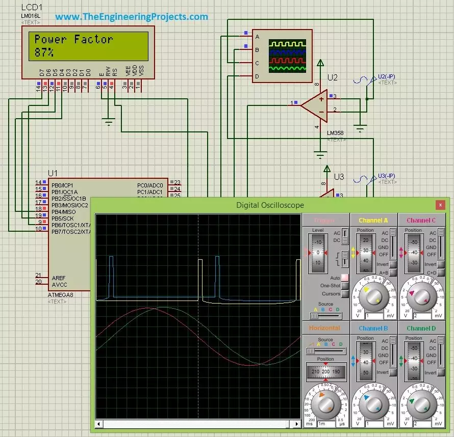
Hello friends, hope you all are fine and having fun. Today's post is about Power Factor Measurement using Microcontroller in Proteus ISIS. As usual, I have this project simulation in which I have to simulate a power factor measuring project using atmega microcontroller. So, I use atmega8 microcontroller and the used Proteus ISIS as the simulating software. Power Factor Measurement isn't that difficult but its a quite tricky and in today's post we are gonna cover it in full detail.

There are many ways for power factor measurement and today's the method we are gonna use is called zero crossing detection. We will first detect the zero crossing of our signal and then we are gonna do the power factor measurement based on the detection of zero crossing of our voltage and current signal. Seems bit difficultdon't worry we are gonna do everything and in quite full detail so stay with me and enjoy the tutorial. But before going into the details of power factor measurement, let's first discuss the basics of power factor measurement because before that you wont understand a bit.

We have designed this simulation after quite a lot of effort so its not for sale but has a quite small cost of $20 so that engineering students can buy it easily. You can buy the simulation along with hex file and code by clicking on the above button and it will lead you to Product page of this product. So, let get started with it.

Basics of Power Factor

  • In AC circuits, there are total three types of loads which are normally bear by an AC current, named as:
    • Resistive Loads.
    • Capacitive Loads.
    • Inductive Loads.

We are all quite well aware of these and if you are not then I must say you wont read further and must first get some basic knowledge about these loads. Among these three loads Resistive loads are known as the most decent loads as they don't mess up with the current and just simply let the current pass through it and that's why there's no such power loss in these types of loads. But when it comes to Capacitive or Inductive loads. they are quite disturbing types of loads and hence they don't let the current easily pass through them and slightly distort the current signals. In case of Capactive loads, the current waveform got ahead of the voltage waveform and hence got a lead angle. In other words, current waveform leads the voltage waveform. While in case of Inductive loads, the scenario is quite the opposite. In Inductive loads, current waveform lags the voltage waveform. The below figure shown the difference between these loads output.

  • In the above figure, Red waveform is showing the current wave, while the green waveform is showing the voltage wave. So its quite obvious from above three figures that in case of resistive load there's no angle difference but in case of capacitive load, current waveform leads the voltage waveform while in Inductive load current waveform lags the voltage waveform and in this case I have used a constant angle of 60 degrees for both capacitive and inductive loads.
  • Now because of this angle difference there's quite an energy loss which is not quite good for any system so the best scenario for any system is that this angle should be 0 which is the case of resistive loads.
  • Now question is why we are reading this stuff while we are actually interested in power factor measurement so yes now I am coming towards it.
  • Power Factor is simply the cosine of this leading or lagging angle. In simple words, if you get this leading or lagging angle between current and voltage waveform, which in the above figure is 60 degrees, and then take the cosine function of that angle, you will get the Power factor for your system.
  • So, if we calculate the power factor for the above waveform, for which the leading or lagging angle (both) are 60 degrees, then we get:

Power Factor = Cos ( 60 degrees )

Power Factor = 0.5

  • So, the power factor of our above system is 0.5 which is quite bad.
  • Now, whats the meaning of this 0.5 power factor, it means that our system's efficiency is 50% and the energy dissipation is also 50% so our system's efficiency is as well 50%.
  • So, if we want to improve our systems' efficiency, then we need to increase the Power Factor of our system.
So, now we have seen the basics of power factor and have got quite an idea about what is it so now let's start with how to measure power factor using Microcontroller in Proteus ISIS.

Power Factor Measurement with Zero Crossing Detection

  • There are many methods available for Power Factor measurement and in this post we are gonna use the zero crossing detection in order to measure it .
  • As we all know, the voltage and current waveform are basically the sine waves so they must cross the zero point at some time.
  • And what we need to do is to detect the zero crossing of both these waves. So, first of all we are gonna do this in Proteus.
  • So, design a circuit in Proteus for Power Factor Measurement as shown in below figure:
 
  • In the above circuit design, I have used two voltage sources which are U2 and U3, I have considered U2 as the voltage transformer while the U3 as the current transformer, when you are designing the actual circuit in hardware then you need to use the current and voltage transformer.
  • The reason why we need to use CT and PT is because the normal voltage is normally of 220V or 110V which we can't directly give to our microcontroller because it will burn our microcontroller.
  • So, we need to lower this voltage level and needs to bring it to such level which is easily operatable by microcontroller, which in normal case is below 5V.
  • So, now I suppose you have used the CT PT and you are getting your current and voltage waveforms in the order of 5V but now again there's another issue that the voltage we are getting is AC while our microcontroller works on DC so we need to find some way to convert this AC into DC.
  • So,in order to do, I have used this 8 pin amplifier LM358 as a comparator.
  • What LM358 is doing ?? Its simply comparing the voltage coming at its inverting pin to the voltage at its non inverting pin and whenever both voltages match it will send a HIGH pulse to the output.
  • You can see clearly that I have placed a GND on the non inverting pin of LM358 so whenever we get zero crossing on the inverting side it will send us a HIGH pulse at output.
  • That's how we are converting our AC signal into DC signal as well as detecting the zero crossing. Let's have a look at these waveform in Oscilloscope.
  • The below two waveform are the current and voltage waveform, red one is current while the green one is voltage and I have placed a lagging angle of 30 degrees that's why current waveform is lagging the voltage waveform.
  • While the above two waveform are the output of LM358 and we can see clearly they are giving the high peaks when the lower waveform cut their zero axis.
  • So that's how we are doing the zero crossing detection.
  • We have got the zero crossing detection and now what we are gonna do in programming is to first detect the zero crossing of current waveform and then we will start counting the time until we get the zero crossing of voltage waveform.
  • So, basically what we are gonna do is we are gonna count the time difference between current wave and voltage wave zero crossing.
  • When we got the time difference between these two waves, we can get the angle quite easily using the below formula.
  • We have got the time difference and we have already know the frequency of our system which is normally 50 HZ or 60Hz.

Power Factor Measurement Using Microcontroller in Proteus

  • Now we have already detected the zero crossing so now next thing is to calculate the time difference which we are gonna do in our microcontroller.
  • So, in order to do the time calculation, first of all we will detect the zero crossing of current wave.
  • Then we will start a timer which will start counting and we will stop this counting when we get the voltage curve.
  • So, in order to do these tasks, I have used the below code:
void pf_func(){
while(1)
{
       if ( PINC.4==1 )
       {
           TCNT1=0;
           TCCR1B = 0x01;
           break;
       }
       else {
               continue;
             }
}
while(1){
     if ( PINC.3 == 1 ){
     TCCR1B = 0x00;
     g=TCNT1;
     break;
}
else {
continue;
}
}
}
  • Now, when we detect the zero crossing of current waveform, we simply start the timer and start counting and when we get the zero crossing of voltage waveform, we simply stop the counter and we get the total time difference between the current waveform and the voltage waveform.
  • Now, next thing we need to do is to calculate the power factor, which is now quite easy because we already got the time difference.
  • So, what I do in order to do that is simply used the below simple code:
int powerfactor(){
k=0;
// To complete number of counts
g=g+1; //Value from the timer
//To convert into seconds
pf=(float)g/1000000;
//To convert into radians
pf=pf*50*360*(3.14/180);
//power facor
pf = cos(pf);
//power factor into percentage
k=abs(ceil(pf*100));
return k;
}
  • So, that's how we are calculating the Power factor.
  • We have done quite a lot of effort to design this simulation and code so its not for free but you can getit easily just for a price of $20.
  • Now when you get the code then make your hex file and upload it in Proteus.
  • Now run your Proteus simulation and you will get something like this:
  • In the above figure, current waveform leads the voltage waveform by 30 degrees and that's why we are getting a power factor of 0.87 which is 87%.
  • Now let me reduce the difference between current and voltage waveform to 0 and we will get a power factor of 1 as shown below:
  • Now, you have seen as we reduced the distance between current and voltage waveform the power factor has increased and as the angle between current and voltage waveform is 0 so its 100%.
That's all for today, I hope you have enjoyed today's post on Power Factor Measurement. You can buy the complete simulation along with hex file and the complete code by clicking on below button.

Buy Power Factor Simulation

So, buy it and test it and hopefully you will get something big out of it. So that's all about Power Factor Measurement using Atmega. I will post it on Arduino as well quite soon and may be on PIC Microcontroller as well. So, till next tutorial take care !!! :)

Scrolling Text on LED Matrix 8x8 using Arduino

Buy This Simulation Hello friends, Hope you all are fine and having fun with your lives. In today's post, I am going to show How to display a Scrolling Text on LED Matrix 8x8 using Arduino in Proteus ISIS. We all know about LED Matrix but if you don't know then google it. :P LED Matrix is used to display long messages, the best thing about LED Matrix is you can combine then in serial way and can make it of any size you want. Like in this post I have combined 8 LED matrices and then displayed my message on them. I have given all the details here but as you can see we have done a great effort in designing this simulation so I haven't posted it free but have placed a very small amount of $20 on it and you can buy it quite easily from our shop by clicking the above button.

I have used Proteus software for the simulation purposes and have use Arduino board as a microcontroller. We know that Proteus doesn't support Arduino but we have a library for it. So, first of all, read Arduino library for Proteus so that you can easily add the Arduino board in your Proteus software and then must also read How to get Hex file from Arduino which we will be uploading in our Proteus software. Its quite easy and you will get it don't in the first attempt. Anyways let's get started with Scrolling Text on LED Matrix 8x8 using Arduino in Proteus ISIS.

Hardware Design of LED Matrix 8x8 using Arduino in Proteus ISIS

  • First of all let's have a look on the hardware design of LED Matrix 8x8 using Arduino in Proteus ISIS, which is shown in below figure:
 
  • So, if you have a closer look on it by clicking it then you can see I have used 8 LED matrices and have used MAX7219.
  • MAX7219 is a shift register which is of real importance here, it takes data serially in and parallel out.
  • It is also known by the name serial in parallel out shift register. We send data to it using single pin which is the data pin and this data is edge triggered by the clock pulse.
  • So when our clock pulse goes from low to high the data is sent to the shift register.
  • We have connected these shift registers in a row as you can see in above figure, the first register is connected to second register via Dout pin.
  • So suppose I have connected two shift register then in this case now I am sending data to two shift register and my output will be of total 16 bits.
  • So, in this way we can add as many shift registers as we want and here I have added total 8 shift registers so my output is total of 64 bits and I am controlling these 64 bits via single pin of Arduino which is data pin of course.
  • Clock Pin and Load Pin are also used here which are used to send the data and then load it in sequence so in short using just 3 pins of Arduino I can control any number of shift register.
  • Now, each shift register is controlling each LED Matrix 8x8 and the reason I am using 8 shift registers is because I am using 8 LED Matrix 8x8.
  • It's a bit tricky but quite simple. So, now we have complete overview of this shift register and how it works, now let's move on to our simulation.

Scrolling Text on LED Matrix 8x8 using Arduino in Proteus ISIS

  • First of all, download the Arduino library for LED Matrix 8x8 by clicking on the below button.

  • Now design a complete circuit as shown in below figure in your Proteus ISIS software:
  • Next thing you are gonna need is the code for Arduino board which is posted below, so copy it and paste it in your Arduino software:
#include <MD_MAX72xx.h>  
#define     MAX_DEVICES   8 
 
#define     CLK_PIN      13  
#define     DATA_PIN     11  
#define     CS_PIN       10  

MD_MAX72XX mx = MD_MAX72XX(DATA_PIN, CLK_PIN, CS_PIN, MAX_DEVICES);  
  
#define SCROLL_DELAY     200
 
#define     CHAR_SPACING     1  
#define     BUF_SIZE     75  
char curMessage[BUF_SIZE];  
char newMessage[BUF_SIZE];  
   
uint8_t scrollDataSource(uint8_t dev, MD_MAX72XX::transformType_t t)  
{  
  static char        *p = curMessage;  
  static uint8_t     state = 0;  
  static uint8_t     curLen, showLen;  
  static uint8_t     cBuf[8];  
  uint8_t colData;  
  
  switch(state)  
  {  
  case 0:  
    showLen = mx.getChar(*p++, sizeof(cBuf)/sizeof(cBuf[0]), cBuf);  
    curLen = 0;  
    state++;  
    
    if (*p == '\0')  
    {  
      p = curMessage;  
    }  
  case 1:       
    colData = cBuf[curLen++];  
    
    if (curLen == showLen)  
    {  
      showLen = CHAR_SPACING;  
      curLen = 0;  
      state = 2;  
    }  
    
    break;  
  case 2:  
    colData = 0;  
    curLen++;  

    if (curLen == showLen)  
     state = 0;  
    
    break;  
    default:  
    state = 0;  
  }  
  return(colData);  
}  
  
void scrollText(void)  
{  
  static uint32_t     prevTime = 0;  
  if (millis()-prevTime >= SCROLL_DELAY)  
  {  
    mx.transform(MD_MAX72XX::TSR);       
    prevTime = millis();  
  }  
}  
  
void setup()  
{  
  mx.begin();  
  mx.setShiftDataInCallback(scrollDataSource);  
  mx.control(MD_MAX72XX::INTENSITY, 10);
  strcpy(curMessage, "www.TheEngineeringProjects.com");

  newMessage[0] = '\0';  
}  
   
void loop()   
{  
  scrollText();  
}
  • Now after uploading the code in Arduino software, get the Hex file for Arduino and upload it in your Arduino board in Proteus ISIS.
  • Now when you upload it to your Arduino board and run your simulation you will get something as shown in below figure:
  • Now let's have a look at How it scrolls, I really have to work hard to make the below figure but it looks cool isn't it. :)
  • So, that's how our website link is gonna scroll from right to left and you can scroll any kind of text.
  • You can buy the complete simulation along with Arduino code and hex file by clicking on below button.

Buy this Proteus Simulation

That's all for today. I hope you guys get some knowledge out of it. Let's meet in the next tutorial, till then take care!!! :)

Interfacing of Keypad with Arduino

Hello friends, hope you all are fine and having fun with your lives. In today's post we will have a look at How to interface keypad with Arduino in Proteus ISIS. Keypad is used almost in every engineering project. If you even look around you will find keypad in many electronic appliances. For example, a simple ATM machine has a keypad on it using which enter our pin code and give commands to the ATM machine. Similarly, calculator also has keypad on it. So, in short there are numerous applications of keypad. You should also read the Real Life examples of Embedded Systems and you will find Keypad in them as well.

Keypad is used where you need to used numerical buttons or you need to use lots of buttons for sending commands so like in some application I need to use 10 buttons so instead of using separate 10 buttons I would prefer to use keypad instead as it will save a lot of time both in hardware as well as programming. So today we will have a detailed look on How keypad works and How we can Interface keypad with Arduino in Proteus ISIS. Proteus also gives keypad component in its database using which we can easily simulate it in Proteus and can save our time. So first simulate it and then design the hardware. After today's post I will also share an Automatic Lock system project using keypad. Anyways let's get started with Interfacing of Arduino with keypad:

How keypad works ??

  • Keypad uses matrix system in order to work.
  • For example, I am using a keypad which has 12 buttons on it as shown in below figure:
  • Now you can see its a 12 button keypad so it has total 3 columns and 4 rows and similarly there are 7 pins to control these 12 buttons.
  • So, the simple formula is total number of pins = Number of Rows + Number of Columns.
  • Now if we look at the internal circuitry of this 12 button keypad then it will look something as shown in below figure:
  • Columns and rows are connected with each other now suppose I press button "1" on the keypad then first row and the first column will get short and I will get to know that button "1" is pressed.
  • Same is the case with other buttons, for example I press button "8" then second column and the third row will get short so this code will remain unique for each button.
  • In simple words, on each button press different column and row will get short we need to detect which one gets short in order to get the pressed button.
Quite simple, isn't it ?? You should also have a look at these Arduino Projects for Beginners. So that's how a keypad works, now let's have a look at How to Interface this keypad with Arduino in Proteus ISIS.

Interfacing of Keypad with Arduino in Proteus ISIS

  • So, now we are gonna interface this keypad with Arduino in Proteus ISIS which is as always my favorite simulator.
  • In Proteus design a circuit as shown in below figure:
  • So, we have an Arduino UNO board along with keypad and LCD.
  • So I have done the programming in such way that whenever you press any button on the keypad, it will get displayed on the LCD.
Note:
  • Now, copy the below code and paste it in your Arduino software and get the hex file from it.
#include <LiquidCrystal.h>
#include <Keypad.h>

const byte ROWS = 4; //four rows
const byte COLS = 3; //three columns
char keys[ROWS][COLS] = {
    {'1','2','3'},
    {'4','5','6'},
    {'7','8','9'},
    {'*','0','#'}
};

byte rowPins[ROWS] = {10, 9, 8, 7}; //connect to the row pinouts of the keypad
byte colPins[COLS] = {13, 12, 11}; //connect to the column pinouts of the keypad

// initialize the library with the numbers of the interface pins
LiquidCrystal lcd(A0, A1, A2, A3, A4, A5);
Keypad keypad = Keypad( makeKeymap(keys), rowPins, colPins, ROWS, COLS );

void setup() {
  // set up the LCD's number of columns and rows:
  lcd.begin(20, 4);
  lcd.setCursor(1,2);
  lcd.print("www.TheEngineering");
  lcd.setCursor(4,3);
  lcd.print("Projects.com");
  lcd.setCursor(0,0);
}

void loop() {
char key = keypad.getKey();

    if (key) {
        lcd.print(key);
    }
}
  • Now upload the hex file in your Arduino UNO in Proteus ISIS and hit the RUN button.
  • If everything goes fine then you will get something as shown in below figure:
  • Now, when you press any button on the keypad it will also appear on the LCD as shown in below figure:
That's all for today. In the coming post I am gonna share a small project in which we will design a automatic locking system using this keypad. So stay tuned and have fun. :)

How to Train Pixy Camera with Computer

In today's post we are gonna have a look at How to Train Pixy Camera with Computer. We have yet posted three tutorials in the Pixy Camera series. In the first tutorial, we have seen How to Get Started with Pixy Camera in which we have studied the basics of Pixy Camera. After that that we have seen the Installation of Pixy Camera Software which is named as PixyMon and in the third tutorial we have covered How to Upload the Latest Firmware in Pixy Camera because its always the best strategy to deal with latest tools. So until now we have configured our Pixy Camera in all possible ways now the next thing is to train our Pixy Camera with Computer using PixyMon software.

Let's first discuss How the Pixy Camera works. Pixy Camera has on board NXP microcontroller which is used for image processing so what we need to do is to let our Pixy Camera remember some objects and whenever this object comes in the range of Pixy camera then it gives output to the microcontroller through SPI protocol. We can use any microcontroller like PIC microcontroller or Arduino etc. We will interface it with Arduino in the coming tutorial but in this tutorial we will have a look at How to train Pixy Camera with Computer using PixyMon. So, let's get started with it.

How to Train Pixy Camera with Computer ???

  • First of all, connect your Pixy Camera with Computer using the Mini USB to USB converter cable which we have seen in the first tutorial.
  • So, plug the mini USB side with your Pixy Camera and plug the USB in your Computer.
  • Now, I suppose that you have already upgraded the Pixy Camera software to latest version.
  • After pluging in Pixy Camera now open Pixy Camera software named as PixyMon, and you will start receving the live video for Pixy Camera in your PixMon as shown in below figure:
  • So I am getting the live video from my Pixy Camera in PixyMon.
  • I have placed a globe in front of the Pixy Camera which we are gonna select now.
  • So, now what I am gonna do is to recognize this globe to the Pixy Camera.
  • In order to do so click Actions and then Set Signature 1 as shown in below figure:
  • Now when you click the Set Signature 1 then video will go static like it stopped and now you need to select a region which you want Pixy Camera to remember as shown in below figure:
  • As you have seen in above figure, I have selected the blue region of globe and now this color is saved in Pixy Camera.
  • After selecting this region, the video will again start but now whenever this blue color of globe comes in focus of Pixy Camera, it will detect this color as shown in below figure:
  • Now you can see it has detected the blue region of globe completely and above it is mentioned s = 1 which means the signature is 1, now suppose you want to save any other color then you can save it in signature 2 or 3.
  • But there's some problem in the image that we are also detecting small blue color in other parts of image as well and you can see at the left below corner it also mentioning s = 1.
  • So, what we need to do is to refine our parameter so that it only detect the blue globe and ignore the other small objects.
  • In order to do so, you have to click File and then Configure and a new Window will pop up which will have the Pixy Parameter range for all the signatures as shown in below figure:
  • Now you can see in the above figure the range for Signature 1 is 2.02400 and we have many small blue blocks in the figure, so now let's reduce this range and check its effect on the video.
  • Now you can see in above figure that our region got quite clear and now its detecting just the globe and all the other small detected regions are now gone.
So, that's how you train Pixy Camera with Computer using PixyMon. You can set other colors as well in other signatures. That's all for today. In the coming tutorial, we will see How to interface Pixy Camera with Arduino in which we will automatically detecting this blue region with Arduino and will be doing our task further. So, stay tuned and have fun. :)  

How to use 18B20 in Proteus ISIS

Hello friends, hope you all are fine and having fun with your lives. In today's post we are gonna have a look at How to use Temperature Sensor 18B20 in Proteus ISIS. I will use Arduino board as a microcontroller and will connect the temperature sensor with it and then will display the code on LCD. I have already posted the same tutorial in which I have done Interfacing of Temperature Sensor 18B20 with Arduino but in that project I have used the real components and designed the hardware. But today, I will just show you the simulation so that you could test the simulation first and then design it in hardware.

Temperature Sensor 18B20 is the most commonly used temperature sensor. Its a one wire sensor means it sends data through a single wire and we can connect multiple sensors with a single wire, that's why its quite efficient and easy to use as well. I have also posted a tutorial on How to Interface LM35 sensor with Arduino in Proteus ISIS which is another temperature sensor so give it a try as well and let me know which one you think is better. Anyways let's get started with temperature sensor 18B20 in Proteus ISIS.

How to use 18B20 in Proteus ISIS ???

  • First of all, get these components from Proteus components list as shown in below figure:
  • Now design the circuit as shown in below figure:
  • As you can see in above simulation, we have used Arduino UNO board along with LCD and 18B20 temperature sensor.
  • 18B20 in Proteus can't detect the real temperature but we can change the temperature by pressing + and - buttons.
  • So, now we have interfaced the temperature sensor and the LCD with Arduino. Next we are gonna design the code for Arduino and will upload it in Arduino baord.
Note:
  • Now download these three libraries, one is "one wire" library which is the protocol for 18B20 temperature sensor, next is the Dallas Temperature sensor library which is the actua library for temperature sensor 18B20 and uses one wire library. Third library is the Crystal LCD library which is used for displaying character on LCD.
  • So, download all these three libraries by clicking on below buttons and then paste them in your libraries folder of Arduino software.

Download One Wire LibraryDownload Dallas Temperature LibraryDownlaod Liquid Crystal Library

  • Now after adding these libraries, open your Arduino software and paste the below code into it.
    #include <OneWire.h>
    #include <DallasTemperature.h>
    #include <LiquidCrystal.h>

    #define ONE_WIRE_BUS 6
    OneWire oneWire(ONE_WIRE_BUS);
    DallasTemperature sensors(&oneWire);

    LiquidCrystal lcd(12, 11, 5, 4, 3, 2);
 
    void setup(void)
    {
    Serial.begin(9600);
    Serial.println("Welcome to TEP !!!");
    Serial.println("www.TheEngineeringProjects.com");
    Serial.println();
    sensors.begin();

    lcd.begin(20, 4);
    lcd.setCursor(5,0);
    lcd.print("Welcome to:");
    lcd.setCursor(1,2);
    lcd.print("www.TheEngineering");
    lcd.setCursor(4,3);
    lcd.print("Projects.com");
    delay(5000);
    }

    void loop(void)
    {
    sensors.requestTemperatures();
    Serial.print("Temperature : ");
    Serial.println(sensors.getTempCByIndex(0));
    //lcd.clear();
    lcd.setCursor(0,0);
    lcd.print("Temperature: ");
    lcd.print(sensors.getTempCByIndex(0));
    lcd.print("C");
    delay(1000);
    }
  • Now get your hex file from Arduino and upload it to your Proteus Arduino board and hit the RUN button.
  • If everything goes fine then you will something like this at the start:
  • After a delay of around 5 sec you will start receiving the Temperature sensor 18B20 values on your LCD as shown in below figure:
  • Now you can see the value shown in the temperature sensor is the same as in LCD.
  • So, now by clicking the + and - buttons on temperature sensor, you can increase and decrease the value of temperature and same will be changed in LCD.
That's how you can do simulation of Temperature sensor 18B20 in Proteus ISIS. Its quite simple and easy to use. That's all for today, hope you get some knowledge out of it.

Upload Latest Firmware in Pixy Camera

[vc_row][vc_column][vc_column_text]

Hello friends, hope you are fine and having fun with your lives. Till now we have seen two tutorials on Pixy Camera module, in the first tutorial we have seen How to Get started with Pixy Camera and after that we have seen How to Install Pixy Camera software which is named as PixyMon. So, now I hope that you have installed the Pixy camera software and have the Pixy Camera module in hand along with USB to Mini USB cable. Because in this tutorial we are gonna plug our Pixy Camera module with moduter and will upload the latest firmware in our Pixy Camera Module, which isn't much difficult and would be a piece of cake if you followed all the instructions carefully.

Pixy Camera comes with some old firmware which is uploaded in it at the time of its manufacturing. But with the passage of tme, the firmware keeps on upgrading and hence in order to make the Pixy Camera module compatible with new software, we have to upgrade the Pixy Camera firmware as well, which we are gonna do in this post.We haven't yet connected our Pixy Camera module with computer so when we plug it with our computer for the first time, it will first install the driver for the usb of pixy Camera board and then we will be able to upload our latest firmware in it. So, before uploading firmware in Pixy Camera first let's have a look at How to install the driver for Pixy Camera module.

How to Install Driver for Pixy Camera ???

  • Plug your USB cable in Pixy Camera from USB mini side and plug the USB side into your computer.
  • Now when you plug your Pixy camera for the first time, a small pop up will open up in the task bar as shown in below figure:
  • And you don't need to do anything and it will get installed automatically. I have tested it on Windows 8 and it works like magic, no problem at all.
  • Now once you installed the driver for Pixy Camera, unplug your pixy Camera USB and now we will see how to upload latest firmware in Pixy Camera.

Upload Latest Firmware in Pixy Camera

  • So, now I hope you have unplugged your Pixy Camera USB from computer.
  • Now download the latest firmware of Pixy Camera by clicking the below button.

  • At the time of writing this post, the latest firmware available was 2.0.17 but you can download the latest firmware by clicking here.
  • Now I hope you have downloaded the latest firmware for pixy Camera, so now open your PixyMon software and first time it will look something as shown in below figure:
  • Now press the white button on your Pixy Camera and plug the USB in your computer while keep pressing the button.
  • Once the USB plugged in and USB got detected, then release the button and you will get something like this in your PixyMon.
  • As shown in above figure, our Pixy Camera got detected and because we pressed the button so that's why it went in programming state.
  • Soon after this a pop up will open up as shown in below figure:
  • Now Browse to your downloaded firmware, which in my case is pixy_firmware-2.0.17-general.hex , so I selected this one and press Open.
  • It will automatically install the firmware and will restart the Pixy Camera and you will get something like this in your PixyMon.
  • That's all, now you will start getting your video from Pixy Camera and you can see in the output pane that it installed the firmware first and then for reset and now ready to use.
Now we have uploaded the Latest Firmware in our Pixy Camera and have also plugged it with our computer and got it working with PixyMon. In the next tutorial, we will see How to train our Pixy Camera using this PixyMon. I am quite tired now so I don't think I am gonna post the next tutorial today, hopefully will post it tomorrow. So, till then take care :)) [/vc_column_text][vc_empty_space height="30px"][/vc_column][/vc_row][vc_row][vc_column width="1/2"][vc_column_text]<< How to Install Pixy Camera Software [/vc_column_text][/vc_column][vc_column width="1/2"][vc_column_text]

How to Train Pixy Camera with PixyMon >>

[/vc_column_text][/vc_column][/vc_row]
Syed Zain Nasir

I am Syed Zain Nasir, the founder of <a href=https://www.TheEngineeringProjects.com/>The Engineering Projects</a> (TEP). I am a programmer since 2009 before that I just search things, make small projects and now I am sharing my knowledge through this platform.I also work as a freelancer and did many projects related to programming and electrical circuitry. <a href=https://plus.google.com/+SyedZainNasir/>My Google Profile+</a>

Share
Published by
Syed Zain Nasir