How to do Arduino Serial Communication ?

Hello everyone, I hope you all are fine and having fun with your lives. In today's tutorial, I am going to share How to do Arduino Serial Communication in detail. Recently, I have shared a lot of tutorial on Arduino Serial Communication which contains everything you need for Arduino Serial Communication. So, in today's tutorial, I am actually gonna combine them all and give you a whole picture of How you can easily do the Arduino Serial Communication. I hope you guys are gonna enjoy this. You should also have a look at DC Motor Speed Control using Arduino in which I have controlled the DC Motor via Arduino Serial Communication. I will also share some more tutorials on Arduino Serial Communication in the near future so I will also add their links in today's tutorial. If you guys have any questions then ask in the comments and we will try our best to resolve your queries. Moreover, most of these codes are testing on Proteus and the simulations are given for download so you can download them from respective link but as a suggestion try to design them on your own. So, let's get started with How to do Arduino Serial Communication:

How to do Arduino Serial Communication ???

  • Arduino boards contain Serial Port in it. If we talk about Arduino UNO then it has the Serial Port at Pin # 0 and Pin # 1 as shown in below figure:
  • These are the Arduino UNO Serial Pins and you can see it has only two pins so which means we can add only one serial device with it. We can use software serial, i am gonna discuss that later.
  • Now Arduino Mega has four Serial Ports on it as shown in below figure:
  • You can see in the above figure that Arduino Mega has:
  • Serial:   Pin # 0(RX) and Pin # 1(TX).
  • Serial1: Pin # 19(RX1) and Pin # 18(TX1).
  • Serial2: Pin # 17(RX2) and Pin # 16(TX2).
  • Serial3: Pin # 15(RX3) and Pin # 14(TX3).
  • So, these are pins through which we can do the Arduino Serial Communication.
  • Now let's have a look at them step by step:
1. How to use Arduino Serial Write
  • First of all you should read How to use Serial Write in Arduino in which I have explained in detail How to send data through Serial Port.
  • In this tutorial I have used Arduino UNO so I have used Pin # 1 which is the TX pin and I am transmitting data Serially.
  • For sending data we use below two commands:

Serial.write("a");

Serial.print("b");

  • You should read the above tutorial because I have explained everything in it.
2. How to use Arduino Serial Read
  • Next tutorial, you need to read is How to use Serial Read in Arduino in which I have explained How you can read data coming through Serial Port and then displayed it on LCD.
  • It's an interesting tutorial and you must read that out. It will help you in understanding How you can receive data through serial port and then use that data.
  • This data could be coming from GPS or GSM or some other serial sensor or device.
  • For reading data though Serial Port you need to use below command:

char data = Serial.read();

  • You must read the above tutorial to have a strong grip on it.
3. How to use Arduino Serial Monitor
  • Once you got the detailed concept of How to read and write data to Serial Port the next thing you need to do is to read about How to use Serial Monitor in Arduino.
  • Arduino Serial Monitor is a great tool needed for Arduino Serial Communication.
  • It works as a debugging tool and I have explained in detail in this tutorial How to use it and do your Arduino Serial Communication.
4. How to use Arduino Serial Flush
  • Flushing Serial data is important if you wanna do a smooth Serial Communication.
  • So, I have posted a tutorial on it in which I have teach How to use Serial Flush in Arduino.
  • For Serial Flushing we use the below command:

Serial.Flush();

  • Serial Flush is not that necessary when you are working on small projects but if you are doing big projects in which you need to deal with a lot of data like GPS then you must consider it.
5. How to use Arduino Software Serial
  • As I have told in the start that Arduino UNO has just one Serial Port so you can only connect one Serial device with Arduino UNO.
  • So, what if you want to do more than one serial device with Arduino UNO then there's you need to know How to use Arduino Software Serial.
  • So you guys must read this tutorial becuase we have to use it a lot in Arduino Projects.
So, that's all for today. I hope you have enjoyed this tutorial. I am gonna add more tutorial in it when I post them on our blog. So till next tutorial take care and have fun !!! :)

How to use Arduino Software Serial ?

Hello friends, I hope you all are fine and having fun. In today's tutorial, I am going to show you How to use Arduino Software Serial. In my previous tutorial, we have had a look at How to use Arduino Serial Write and How to use Arduino Serial Read. In both of these tutorials, we have done the hardware Serial Communication. But we all know that Arduino has just one Serial Port placed at pins 0 and 1.

So, if you are having two or more serial modules, then there's difficulty in adding two modules because we just have one hardware serial port. So, in such cases, there's a need to add one more serial port and that serial port can be created at any two pins of Arduino and is called software serial. Software Serial is also named Virtual Serial Port.

It's really very comfy if you are working on serial modules. If you ask me, I have never used a hardware serial port because pin # 0 and pin # 1 are also used for uploading code and debugging the code via Arduino Serial Monitor. So, I always connect my Serial modules via software serial and then check their output on Serial Monitor. So, let's get started with How to use Arduino Software Serial:

Where To Buy?
No.ComponentsDistributorLink To Buy
1Arduino UnoAmazonBuy Now

How to use Arduino Software Serial?

  • I am going to use Proteus software for testing the codes.
  • You can download the Proteus Simulation for Arduino Software Serial, by clicking the below button:
Download Simulation & Code

Arduino Code

  • First of all, let me tell you where you can find Examples of Software Serial.
  • Arduino has a Library of Software Serial in it. If you can't find its library then you should download the Software Serial Library.
  • Now copy and paste the below code in your Arduino software:
#include <SoftwareSerial.h>

SoftwareSerial SoftSerial(2, 3);

void setup()
{
  Serial.begin(9600);
  SoftSerial.begin(9600);
  
  SoftSerial.println("       **** Its a Software Serial **** ");
  SoftSerial.println(" Designed by www.TheEngineeringProjects.com");
  SoftSerial.println();
  
  Serial.println("       **** Its a Hardware Serial **** ");
  Serial.println(" Designed by www.TheEngineeringProjects.com");
  Serial.println();
}

void loop()
{
      
      if (Serial.available())
      {
           char data = Serial.read();
           SoftSerial.print(data);
      }
}
  • In the above code, we have first included the Arduino Software Serial Library using #include<SoftwareSerial.h>.
  • After that, I have created the SoftSerial object and its parameters are SoftSerial(RX, TX), so in the above code pin # 2 has become RX of our Arduino Software Serial and pin # 3 become TX.
  • Now our SoftSerial object is ready and then we have initialized our software serial by using SoftSerial.begin(9600), here we have started our software serial and the baud rate set is 9600.

Proteus Simulation

  • Now design a small circuit in Proteus, you will need Arduino Library for Proteus to use Arduino in Proteus, as shown in the below figure:
  • Now get the Arduino Hex File and upload it to your Proteus software.
  • Now run your Proteus Simulation and you will get something as shown in the below figure:
  • So, it's printed there that one is hardware serial and second is software serial and you can see the software serial is connected to Pin # 2 and Pin # 3.
  • Now when you write something in the Hardware Serial, it will also get printed in the Software Serial, that's the code which we have added in the loop() section.
So, that's all for today, I hope you have enjoyed this Arduino Software Serial example. Download the Simulation from the above button and try to design it on your own. Take care and have fun !!! :)

How to use Arduino Serial Flush?

Hello friends, I hope you all are fine and having fun with your lives. Today, I am going to share a very quick and basic tutorial in which I will show you How to use Arduino Serial Flush. I hope you guys are going to like it. We have seen How to use Arduino Serial Write? In that tutorial, we have sent some data over the Serial Port so you must recall that tutorial because we are going to use the same example today. Moreover, it's also good if you have a look at How to use Arduino Serial Monitor because that's also related.

Moreover, I hope that's going to be my last lecture on Arduino Serial Port because I have covered it in full detail. Although I am going to summarize all the Arduino Serial Post Commands in a single Post. You should also have a look at How to do Arduino Serial communication because, in that tutorial, I have combined all Arduino Serial Projects. Anyways, let's get started with How  to use Arduino Serial Flush:

Where To Buy?
No.ComponentsDistributorLink To Buy
1Arduino UnoAmazonBuy Now

How to use Arduino Serial Flush?

  • Arduino Serial Flush is used to flush the data sent through Arduino Serial Port.
  • When we send data on a serial port through Arduino then we use the command Serial.print() or Serial. write().
  • So when the data is sent it is sent using interrupt and when we use Arduino Serial Flush command then it makes sure that all the data is sent through serial port and nothing's left in the stream.
  • In simple words, it clears the serial data stream and kind of refreshes it and also makes you ready to send the next data.
  • Here's the syntax to use the Arduino Serial Flush command:

Serial.flush();

  • It doesn't return anything that's why we haven't assigned any variable to it.
  • It's just a simple function that clears the data on the transmitting pin of Arduino.
  • Now, if you want to remove that on receiving pin of Arduino, then you just need to write this command:

while(Serial.available());

  • But you make sure while using the above command because if you are receiving the data continuously then your code will remain stuck and won't move forward unless you got the complete data.
  • So, here's the small code which I have also used in the Arduino Serial Write tutorial but now I am using the Arduino Serial Flush command too.
  • So, here's the code:
#include 
 
// initialize the library with the numbers of the interface pins
LiquidCrystal lcd(13, 12, 11, 10, 9, 8);
 
void setup() {
  // set up the LCD's number of columns and rows:
  lcd.begin(20, 4);
  // Print a message to the LCD.
  lcd.setCursor(1,0);
  lcd.print("www.TheEngineering");
  lcd.setCursor(4,1);
  lcd.print("Projects.com");
  lcd.setCursor(1,0);
  Serial.begin(9600);
 // lcd.clear();
  
  Serial.write("www.TheEngineeringProjects.com");
  Serial.flush();
}
 
void loop() 
{
}
  • In the above code, I have simply added the Arduino Serial Flush code and now it will take a little more time to complete because now it will make sure that all the data has been sent.
So, that's all for today. I hope you guys have enjoyed this short Arduino Serial Flush tutorial. If you have any questions, please ask in the comments. Take care !!! :)

How to use Arduino Serial Monitor ?

Hello friends, I hope you all are fine and having fun with your lives. In today's tutorial, I am going to show you How to use Arduino Serial Monitor. It's not gonna be a very big post but its really very essential if you wanna learn Arduino coding. Because Arduino Serial Monitor is a great debugging tool and it helps a lot in Arduino Projects. In the previous post we have seen How to use digitalRead in Arduino and if you recall that tutorial then you must remember that in it we have used some Serial printing. So that's what we are gonna cover in today's tutorial. Before going into the details, I must suggest you to first read these two posts because in those tutorials I have shown the serial communication which is essential for Serial Monitor Working. So, you guys must first read them and then continue this tutorial. IF you have any questions then ask in the comments. So, now let's get started with Introduction of Arduino Serial Monitor:

How to open Arduino Serial Monitor ?

  • There are two ways to open Arduino Serial Monitor, so let's discuss both of them one by one:
First way
  • Open your Arduino Software and then click on the small box in the right top corner as shown in the below figure:
  • Your Arduino must be connected to your computer when you click this Serial Monitor.
  • If Arduino is not connected then it will create error but if Arduino is connected and configured then it will open a new window as shown in below figure:
  • This new window is called Arduino Serial Monitor, we are gonna discuss how to use it in the next section, let's have a look at the second way of opening it:
Second Way
  • You can also open it by clicking on the Tools in the Top Menu and then click Serial Monitor and same Serial Monitor will open up as shown in below figure:
  • You can also use the short keys Ctrl+Shift+M to open Arduino Serial Monitor.
  • So, that's all about How to open Arduino Serial Monitor. So, now let's have a look at How to use it and why to use it ? :)

What is Arduino Serial Monitor ?

  • Arduino Serial Monitor is a simple tool available in Arduino software.
  • Arduino Serial Monitor is used in Serial communication and it prints data, whatever you send through the serial port of Arduino will also be view able on this Serial Monitor.
  • In Windows XP, we have a Hyper Terminal which is used for Serial communication and this Arduino Serial Monitor is just a replica of that Hyper Terminal.
  • So, using this Arduino Serial Monitor you can check what you are sending and you can also place checks in your code.
  • For example, I want to check the status f any digital Pin then I can simply Serial print it that when some button is pressed then I will be notified.
  • I am gonna discuss it in detail further. but first let's have a simple data sending on Serial Monitor.
  • So, connect your Arduino and then upload the below code in it:
void setup() {
  Serial.begin(9600);
  Serial.print("www.TheEngineeringProjects.com");
}

void loop() {
  // put your main code here, to run repeatedly:

}
  • Now you can see in the above code that I just begin my serial port and then I have used the command Serial.print to print some data on the Serial Port.
  • So, now upload this code in your Arduino board which must be connected to your computer in order to work this Serial Monitor.
  • After uploading the code, now open your Serial Monitor and you will get this data in your Serial Monitor which means this data has been sent Serially as shown in below figure:
  • Now you can see that our data has been sent serially.
Note:
  • Serial Monitor is using the Serial Port so that's why its directly connected to Pin # 0 and Pin # 1 of Arduino.
  • When you open your Serial Monitor then your Arduino resets.
  • You can change the baud rate from lower right corner so because we have begin our Serial port with baud rate 9600 that's why I have selected 9600 in Serial Monitor.
  • Now if you manually want to send some data on the Serial Port of your Arduino (RX) then you can type in above bar and then click Send.
  • So, let's design a small code in which we will send the data on the Serial Port which will be received on it.
  • So, upload the below code in your Arduino and open your Serial Monitor.
void setup() 
{
    Serial.begin(9600);
    Serial.println("www.TheEngineeringProjects.com");
}

void loop() 
{
    if(Serial.available())
    {
        char data = Serial.read();
        Serial.print(data);
    }
}
  • Now, open your Serial Monitor and type something in it and it will be printed on your Serial Monitor as shown in below figure:
  • So, I have printed my name and then Send it and it is printed on the Serial Monitor.
  • Now, you know both ways of How to use Arduino Serial Monitor, now let me tell you where you can use it.

Serial Monitor as a Debugging Tool

  • Serial Monitor is a great debugging tool.
  • You can place checks in your code like you wanna see how many lines are working.
  • So, if your code is of like 500 lines then you can place check in between like after 100 lines to see if its working or not.
  • Similarly, if you are dealing with some GPS module then you can receive its data via the Software Serial and then can print it on the Serial Monitor to see that you are getting the data correctly.
  • For having a look at Serial Data Receive you should check Send SMS using Sim900 and Arduino because in that post I have sent data over Serial Port and received data and then printed it on Serial Monitor.
  • Here's an awesome video in which one of our team members has shown how to use Arduino Serial Monitor:
So, that's all about the Arduino Serial Monitor and I hope you guys have enjoyed it. I am gonna share more Arduino basic tutorials soon. Take care !!! :)

How to use digitalRead in Arduino ?

Hello everyone, I hope you all are fine and having fun. Today's tutorial is the next episode in the series of basic Arduino tutorial for Beginners. In today's tutorial, we are gonna have a look at How to use digitalRead in Arduino. In the previous tutorial, we have seen How to use pinMode Arduino Command, which sets the Arduino Pin either as Input or Output. So, if you are using this pin as input then you have to read its status and that's where you need to use this digitalRead Arduino Command. Other than Serial Pins in Arduino UNO, we also have 12 digital Pins. Serial Pins are also digital Pins so in total we have 14 digital Pins in Arduino UNO starting from 0 to 13. I am gonna explain them in detail in today's tutorial and we will also have a look at How to use this digitalRead command in Arduino. So, let's get started with it:

How to use digitalRead in Arduino ?

  • As I have explained in the above section that Arduino UNO has 14 digital pins in total starting from 0 to 13 as shown in below figure:
  • So, you can see in the above figure that we have RXD at 0 which is sued for Serial receiving and then we have TXD at 1 used for Serial writing.
  • So, these pins from 0 to 13 are all digital and after these digital Pins we have GND.
  • Now I hope you have got the idea of digital Pins.
  • Next thing is How to use these digital Pins, normally we connect different digital sensors with these digital Pins.
  • For example, I have a digital Sensor named as Vibration Sensor. This sensor gives HIGH when it feels vibrations and gives LOW in normal condition.
  • So, I am gonna connect the Signal Pin of this Sensor with any digital Pin of Arduino.
  • Now, coming towards digitalRead command, this digitalRead command is used in Arduino for reading the status of digital Pins on Arduino.
  • So, when we want to read whether the digital Pin of Arduino is HIGH or LOW, we use this digitalRead command.
  • The syntax of digitalRead is as follows:

int Reading = digitalRead (int PinNumber);

  • digitalRead command takes one input which is the value of the Pin, like if you wanna read the digital status of Pin # 8 then you have to enter 8 in the small brackets of digitalRead.
  • digital Read returns Boolean data which is either HIGH or LOW and it is saved in the integer variable which I have named Reading in the above syntax. We have discussed it in Arduino Datatypes.
  • So, let's have a look at the example of digitalRead:

Reading = digitalRead (8);

  • In the above example, I am reading the status of digital Pin # 8 of Arduino and saving it value in the Reading variable.
  • So, I hope now you have understood completely How to use the digital Read in Arduino.
Note:
  • One important thing to note here is that because we are reading the data from digital Pin so that digital Pin must have to be an input.
  • So, you need to declare that Pin as an input.
  • So, let's have a look at a small code in which we will read the status of pin # 8 of Arduino and then display its status on Serial Monitor.
  • I hope you have already read How to write Arduino Code and knows its basics.
int Pin = 8; // Initializing Arduino Pin
int Reading;

void setup() {
  pinMode(Pin, INPUT); // Declaring Arduino Pin as an Input
}

void loop() {
  Reading = digitalRead(Pin); // Reading status of Arduino digital Pin
  
  if(Reading == HIGH)
  {
    Serial.println("HIGH");
  }

  if(Reading == LOW)
  {
    Serial.println("LOW");
  }
 
}
Summary
So, here's a short summary of the above discussion for a quick revision: Definition:
  • digitalRead is used to read the status of any digital Pin in Arduino.
  • We have to give the digital Pin number in the small brackets.
Syntax:
  • Syntax of digital Read is:

int Reading = digitalRead (int PinNumber);

Return:

  • digitalRead returns HIGH or LOW depending on the status of corresponding digital Pin.
Example:

Reading = digitalRead (8);

Restriction:

  • Before reading status of any digital Pin, we have to first declare that Pin as an input.:

pinMode(8,INPUT);

So, that's all about today. I hope you have enjoyed today's tutorial and are gonna learn something out of it. In the next tutorial, we will have a look at How to use DigitalWrite Arduino Command, which is used to update the status of digital Pins. Let me know if you have any questions in it. Take care !!! :)

How to use Arduino Serial Write?

Hello everyone, I hope you all are fine and having fun with your lives. Today, I am going to share the next tutorial in this series of basic Arduino tutorials and it's named How to use Arduino Serial Write. In this tutorial, I have given an overview of How to use the Arduino Serial Write Command. In the previous tutorial, we have seen How to use Arduino Serial Read? in which we have read the data coming from the serial port.

While today we will have a look at how to send the data through a serial port in Arduino and for that, I am going to use the Arduino Serial Write command. It's also going to be a very simple and basic Arduino tutorial but if you are new to Arduino then you must read it completely as it will gonna help you out. I have also designed a Proteus Simulation and explained it at the end of this tutorial. I hope you guys are gonna learn from it:

How to use Arduino Serial Write ???

  • In the Arduino Serial Read, we have seen that How to read data coming from the serial port and we have used Pin # 0 for that purpose.
  • So, now we are going to write some data on the Serial Port.
  • It's like we are sending data from Arduino to some other device via Serial Port.
  • For example, you are using a GSM module with Arduino then you have to send AT commands to your GSM board from Arduino and that's where you use Arduino Serial write.
  • You can download the Proteus Simulation and code for Arduino Serial Write Command by clicking the below button:
Download Simulation and Code
  • Here's the first syntax for Arduino Serial write:
Arduino Serial Write Syntax 1:
  • Arduino Serial Write is used to write some data on the Serial Port and it sends data in binary form.
  • Here's Arduino Serial Write Syntax:

Serial.write ( 'DataSent' ) ;

where:

  • DataSent is a simple byte and is used in these characters ' '. The below example code will send byte '1' on the serial port:

Serial.write ( '1' ) ;

  • Now, let's write some data on Arduino Serial Port using the above syntax and see what we got.

Proteus Simulation

  • So, design a Proteus Simulation as shown in the below figure:
#include <LiquidCrystal.h>

// initialize the library with the numbers of the interface pins
LiquidCrystal lcd(13, 12, 11, 10, 9, 8);

void setup() {
  // set up the LCD's number of columns and rows:
  lcd.begin(20, 4);
  // Print a message to the LCD.
  lcd.setCursor(1,0);
  lcd.print("www.TheEngineering");
  lcd.setCursor(4,1);
  lcd.print("Projects.com");
  lcd.setCursor(1,0);
  Serial.begin(9600);
  lcd.clear();
  
  Serial.write('1');
}

void loop() 
{
}
  • In the above code, I have simply written a byte which you can see is 1.
  • So, now upload it and run your simulation and if everything goes fine then you will get 1 on your virtual serial terminal of Proteus, as shown in the below figure:
  • You can see in the above figure that we got 1 in Serial Port so now you can send whatever you want via this Arduino Serial Write Command.
  • Now let's have a look at the second syntax of the Arduino Serial Write command:
Arduino Serial Write Syntax 2:
  • We can also send a String of bytes via Arduino Serial Write Command. Here's the syntax:

Serial.write ( "DataSent" ) ;

where:

  • DataSent is a simple byte and is used in these characters " ". The below example code will send our site address on the serial port:

Serial.write ( "www.TheEngineeringProjects.com" ) ;

  • Now let's sent a string of bytes through this Arduino Serial Write Command, so I have used the below code and have sent our website address via Serial Write.
  • So, use the below code and get your Hex File:
#include <LiquidCrystal.h>

// initialize the library with the numbers of the interface pins
LiquidCrystal lcd(13, 12, 11, 10, 9, 8);

void setup() {
  // set up the LCD's number of columns and rows:
  lcd.begin(20, 4);
  // Print a message to the LCD.
  lcd.setCursor(1,0);
  lcd.print("www.TheEngineering");
  lcd.setCursor(4,1);
  lcd.print("Projects.com");
  lcd.setCursor(1,0);
  Serial.begin(9600);
 // lcd.clear();
  
  Serial.write("www.TheEngineeringProjects.com");
}

void loop() 
{
}
  • Run your Proteus Simulation and you will get the below results:
  • You can see in the above figure that we got the whole address via Serial Port.
That's all for today, I hope you guys have enjoyed today's post. In the coming post, I am gonna discuss the Arduino Print Command. Thanks for reading. Take care.

How to use Arduino Serial Read ?

Hello friends, I hope you all are fine and having fun with your lives. Today, I am going to share a very basic and introductory tutorial named How to use Arduino Serial Read. I am sharing this tutorial because I am getting a lot of emails in which users normally ask about basic Arduino tutorials as they are very new to them. So, I thought of sharing this very basic Arduino tutorial in which we are going to have a look at how we can use the Arduino Serial Read command.

I selected this tutorial as my first tutorial in this list of Arduino basic tutorials because learning to use Serial port is very necessary as it's one of the best troubleshooting tools for your code. I have also given a Proteus Simulation in which I have received the incoming data from the serial port and displayed it on LCD. Before going into the details of this Arduino Serial Read, let me first discuss the Serial Port in General.

Where To Buy?
No.ComponentsDistributorLink To Buy
1LCD 16x2AmazonBuy Now
2Arduino UnoAmazonBuy Now

What is Serial Port?

  • I have already written a detailed tutorial on this topic which you can read at What is Serial Port?
  • Serial Port is used for data communication between two electronic modules, both should support serial ports.
  • Serial Port has 9 pins in total used for different purposes.
  • The two of these pins most commonly used are TX (transmitter) and RX (Receiver).
  • So, using these two pins we send our data from one place to another.
  • Now let's have a look at Arduino Serial Port first, before having a look at Arduino Serial Read.

Serial Port in Arduino

  • Almost all Arduino boards support Serial Port.
  • If we talk about Arduino UNO, it has one serial port on it and it is located at pin 0 and pin 1.
  • If you look closely at the Arduino UNO board then you can see a little TX is written on its pin # 1 and a little RX is written on its pin # 0, as shown in the below figure:
  • So, now we have got the Serial Port on Arduino UNO which we know are at pin # 0 and pin # 1, now in the next part, we are going to have a look at How to use Arduino Serial Read and get data from this Serial Port.

How to use Arduino Serial Read?

  • Arduino Serial read command is used for reading any data available at the Serial Port of Arduino board.
  • I have also designed a Proteus simulation which you can download from the below button, and I have explained this simulation in the last step of this tutorial:
Download Simulation & Code
  • For example, you have some serial module, let's say GPS module (most of the GPS module works at serial port).
  • So, when you connect your GPS module with Arduino, you have to connect the TX pin of GPS with the RX pin of Arduino.
  • Now the TX pin of GPS will be sending/transmitting the data and because this pin is connected with the RX pin of Arduino, so Arduino will keep receiving the data.
  • Now the data is coming to Arduino but you have to write some code to read this incoming serial data and then save it in some variable.
  • And in order to read this data, we need to use the Arduino Serial Read command.
  • Arduino Serial read command reads the incoming data from Serial Port and then saves it in some variable.
  • Here's the syntax of the Arduino Serial Read command:

char data = Serial.read();

  • One important thing is, in order to make Arduino Serial Read command work, you have to first initialize the Serial Port in Arduino, as shown below:

Serial.begin(9600);

Note:
  • Arduino USB Port which is plugged into the computer and is used for uploading code also works on the same serial port.
  • So, if you have anything plugged in pin # 0 of Arduino then you can't upload the code in Arduino.
Now, let's design a simple example in which we will be receiving data from Serial Port and then saving it in some variable.
  • So, connect your Serial device with your Arduino board and now upload the below code to your Arduino board:
void setup() {
  Serial.begin(9600); // Serial Port initialization
}

void loop() {
  if(Serial.available()) // Chek for availablity of data at Serial Port
  {
    char data = Serial.read(); // Reading Serial Data and saving in data variable
    Serial.print(data); // Printing the Serial data
  }
}
  • Now, you need to open the Serial Monitor of Arduino which is used for debugging purposes.
  • So, whenever you write something on Serial Port, it got printed on the Serial monitor.
  • So, whatever you will be receiving in the Serial Port you will get in the Serial Monitor.
  • Here are some random data of GSM module coming on serial port and showing in serial monitor:

How to use Arduino Serial Read in Proteus?

  • So, now let's design a small Proteus simulation in which we will see how to use Arduino Serial Read.
  • Proteus doesn't have Arduino boards in it, so you need to first download this Arduino Library for Proteus and then you will be able to simulate your Arduino board in Proteus.
  • So, design a simple circuit as shown in the below figure:
  • In the above figure, I have placed an LCD and I will get the data from the serial port and then I will print that data on LCD.
  • So, in simple words, whatever I type in the Virtual terminal will be shown on LCD.
  • You also need to download this New LCD Library for Proteus to get this amazing LCD in Proteus.
  • So, now use the below code and Get your Hex File from Arduino Software:
#include <LiquidCrystal.h>

// initialize the library with the numbers of the interface pins
LiquidCrystal lcd(13, 12, 11, 10, 9, 8);

void setup() {
  // set up the LCD's number of columns and rows:
  lcd.begin(20, 4);
  // Print a message to the LCD.
  lcd.setCursor(1,0);
  lcd.print("www.TheEngineering");
  lcd.setCursor(4,1);
  lcd.print("Projects.com");
  lcd.setCursor(1,0);
  Serial.begin(9600);
}

void loop() {
  if(Serial.available()) // Chek for availablity of data at Serial Port
  {
    char data = Serial.read(); // Reading Serial Data and saving in data variable
    Serial.print(data);
    lcd.print(data); // Printing the Serial data
  }
}
  • Now when you start the Proteus simulation the first screen will look something like this:
  • Now whatever you write in your Serial Port, will show on the LCD as shown in below figure:
  • That's how the Arduino Serial Read works.
  • You can download this Proteus simulation and the Arduino code by clicking the Download button given at the start of this post.
So, that's how you can use the Arduino Serial Read command and can do your task. If it's still difficult for you then let me know on comments and I will try my best to resolve your issues. Thanks.

Line Following Robot using Arduino

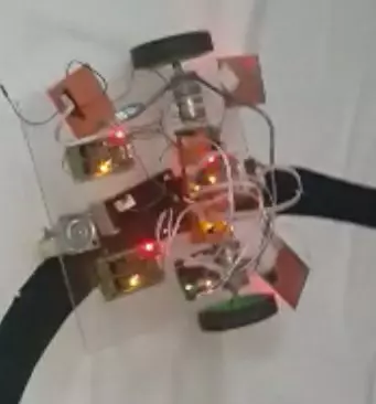
Hello everyone, I hope you all are fine and having fun with your lives. Today, I am going to share a very basic project named as Line Following Robot using Arduino. I have designed a three wheeler robot and have placed IR sensors beneath it to detect the black line and then I have made it move over this Black Line.

This Line Following Robot is not doing any extra feature i.e. turning or rotating back. It will just simply move in the straight line. I have also posted a short video at the botton of this tutorials which will give you better idea of how this robot moves. You should first read this tutorial and design the basic robot and once you are successful in designing the basic Line Following Robot then you should have a look at my recent Project Line following Robotic Waiter in which I have designed a Robotic waiter which follows the line and also take turns on different tables. So, let's get started with Line Following Robot using Arduino.

Line Following Robot using Arduino

  • First of all I have designed the Mechanical model of the robot, which has three wheels on it.
  • Its a triangular method in which the motors were attached to the front two wheels and the back wheel is a caster wheel, which is present in the middle of the robot.
  • Here's the image of front wheel coupled with the DC Gear Motor:
  • Now let's have a look at the rear caster wheels, shown in below image:
  • Finally, I have used Acrylic as the body of the robot.
  • Here's the assembled version of our Line Following Robot:
  • Now that we have the mechanical design of our robot and we have assembled it completely.
  • So, now comes the electronics part where we are gonna place the DC Motor Driver Circuits and will also place the IR sensors.
  • I have used Arduino board for programming of this Line following Robot.
  • First of all, I have designed the 2 relay baord for DC motors.
  • Its circuit diagram is shown in below figure:
  • We also need a voltage divider circuit because we need such a power supply from which we can get 5V, while our source battery is of 12V.
  • So, in order to do that I have used 7805 Regulator IC and have designed a simple circuit as shown in below figure:
  • Now placing all the components over the Line following Robot, it looked like something as shown in below figure:
  • Here's the Arduino code which you need to upload in your Arduino board:
#define motorL1 8
#define motorL2 9
#define motorR1 10
#define motorR2 11

#define PwmLeft 5
#define PwmRight 6

#define SensorR 2
#define SensorL 3
#define Sensor3 A0
#define Sensor4 A1

#define TableA A4
#define TableB A2
#define TableC A5
#define TableD A3

int OriginalSpeed = 200;
int TableCount = 0;
int TableCheck = 0;
int RFCheck = 10;

void setup() 
{
  Serial.begin (9600);
 
  pinMode(motorR1, OUTPUT);
  pinMode(motorR2, OUTPUT);
  pinMode(motorL1, OUTPUT);
  pinMode(motorL2, OUTPUT);
  
  pinMode(PwmLeft, OUTPUT);
  pinMode(PwmRight, OUTPUT);
  
  pinMode(SensorL, INPUT);
  pinMode(SensorR, INPUT);
  pinMode(Sensor3, INPUT);
  pinMode(Sensor4, INPUT);
  
  pinMode(TableA, INPUT);
  pinMode(TableB, INPUT);
  pinMode(TableC, INPUT);
  pinMode(TableD, INPUT);
  
  MotorsStop();
  
  analogWrite(PwmLeft, 0); 
  analogWrite(PwmRight, 0);
  delay(2000); 
 // Serial.println("fghfg");
  
}

void loop() {
  MotorsForward();
  PIDController();
}

void MotorsBackward()
{
    digitalWrite(motorL1, HIGH);
    digitalWrite(motorL2, LOW);
    digitalWrite(motorR1, HIGH);
    digitalWrite(motorR2, LOW);
}

void MotorsForward()
{
    digitalWrite(motorL1, LOW);
    digitalWrite(motorL2, HIGH);
    digitalWrite(motorR1, LOW);
    digitalWrite(motorR2, HIGH);
}

void MotorsStop()
{
    digitalWrite(motorL1, HIGH);
    digitalWrite(motorL2, HIGH);
    digitalWrite(motorR1, HIGH);
    digitalWrite(motorR2, HIGH);
}

void MotorsLeft()
{
    analogWrite(PwmLeft, 0); 
  analogWrite(PwmRight, 0);
    digitalWrite(motorR1, HIGH);
    digitalWrite(motorR2, HIGH);
    digitalWrite(motorL1, LOW);
    digitalWrite(motorL2, HIGH);
}

void MotorsRight()
{
      analogWrite(PwmLeft, 0); 
  analogWrite(PwmRight, 0);
    digitalWrite(motorR1, LOW);
    digitalWrite(motorR2, HIGH);
    digitalWrite(motorL1, HIGH);
    digitalWrite(motorL2, HIGH);
}

void Motors180()
{
    analogWrite(PwmLeft, 0); 
    analogWrite(PwmRight, 0);
    digitalWrite(motorL1, HIGH);
    digitalWrite(motorL2, LOW);
    digitalWrite(motorR1, LOW);
    digitalWrite(motorR2, HIGH);
}

void PIDController()
{
  if(digitalRead(SensorL) == HIGH){analogWrite(PwmRight, 250);analogWrite(PwmLeft, 0);}
  if(digitalRead(SensorR) == HIGH){analogWrite(PwmLeft, 250);analogWrite(PwmRight,0);}
  if((digitalRead(SensorL) == LOW) && (digitalRead(SensorR) == LOW)){analogWrite(PwmRight, 0);analogWrite(PwmLeft, 0);}
}
  • Now that's all, here's the video for Line Following Robot using Arduino which will give you better idea:
That's all for today. I hope you have enjoyed this Line Following Robot using Arduino and are gonna use it in your projects. feel free to ask in comments, if you got into any trouble. Thanks for reading. Take care !!! :)

Getting Started with Cayenne - Arduino

Hello friends, I hope you all are fine and having fun with your lives. Today, I am going to share a new and very exciting service with you guys which is named as myDevices Cayenne, we will have a look at getting started with Cayenne. Its really an awesome platform for students and hobbyist who wants to work on embedded systems but are afraid of programming codes.

Cayenne is an online project building platform using drag and drop. Currently it supports Arduino and Raspberry Pi. In simple words, you can design any of your Arduino or Raspberry Pi project simply by drag and drop different components. You don't need to write any code, you just need to place your blocks and upload it to your Arduino board. Its also known as the Graphical coding.

I came to know about Cayenne a few days ago and I have really enjoyed working on it so I thought to share it with you guys so that you can also get benefit from it. In today's tutorial, I am just gonna give an overview of Cayenne and we will design a simple Arduino LED project on it. In the coming tutorials I will share different projects on Cayenne, which will help you guys in your projects. Moreover, first we will cover the Arduino Project on Cayenne and later we will work on Raspberry Pi as well. So, let's have a look at Getting Started with Cayenne.

Getting Started with Cayenne

  • First of all, what you need to do is to open this myDevices Cayenne Website.
  • Now on this myDevices Cayenne Website you have a to create a free account so click on the Green Button which says Get Started for Free.
  • So, fill out the form on the Registration page and then it will ask you which one you want to use as shown in below figure:
  • Now as we are gonna work on Arduino so I will select Arduino among them.
  • You must have the Arduino IDE installed on your computer and you should also install the Cayenne Library for Arduino.
Note:
  • When I first started working on Cayenne, I had an older version of Arduino software and when I compiled the code then it generated errors, so I updated my Arduino software and it worked fine.
  • So, you just make sure to have the latest Arduino IDE.
  • Next thing you need is the Arduino Ethernet or Arduino Wifi Shield, which will be used for uploading the code to Arduino board from Cayenne website.
  • So, now plug your Ethernet or Wifi shield on the Arduino board.
  • I have plugged Arduino Wifi shield with Arduino UNO.
  • So, now once you selected the Arduino then on the nex page you will get some instructions, which I have already disscused.
  • Now you should plug your Arduino board with your computer and click Next.
  • In this step you need to select your device as shown in below figure:
  • In the above figure, you can see first of all, I have selected the Arduino UNO shield becasue I want to upload the code in this shield and then I have selected the Wifi Shield using which the code will be uploaded.
  • Now when you click on the Sketch button you will get a small sketch which you need to upload in your Arduino board.
  • This is the only code which you need to upload, this code is acting as a bridge between Arduino and Cayenne.
  • Once you uploaded that code then Cayenne will automatically detect your board, you just need to wait.
  • As soon as your board is detected, you will be redirected to your Dashboard, where you can design your first project as shown in below figure. :)

Arduino LED Blinking Project in Cayenne

  • Now Click on the Create new Project button and give it a name, I have given it Arduino LED and click OK.
  • The new project will be created, now we need to add the LED Control in it.
  • So, in order to do so you need to click on the Add new button and then Device/ Widget as shown in below figure:
  • You can see in the above figure, that all the devices are now visible.
  • As we are working on the LED, so you need to click the Light icon, which is among Actuators.
  • When you click it you will get something as shown in below figure:
  • So, I have selected the Light switch and in its properties, I have selected the D8 which is 8th digital Pin of Arduino.
  • Now click on the Add Actuator button and you are done.
  • You first LED Blinking Project is done on Cayenne and it will look something as shown in below figure:
  • So, now when you click this light switch your LED on pin 8 will go ON and if you click it again then it will go OFF.
  • I have plugged an LED on Pin # 8 on my hardware.
  • In the below video, I have explained this Arduino LED project in more detail, so must watch it:
I hope you guys have enjoyed today's tutorial and are gonna like this Cayenne online Platform. I will post more tutorial on it in which I will interface all these devices with Arduino. So, stay tuned and have fun !!! :)

LPG Gas Leak Detector using Arduino

Hello friends, hope you all are fine and having fun with your lives. Today, I am going to share a new project named LPG Gas Leak Detector using Arduino in Proteus ISIS. Before reading this tutorial, you must first download the Gas Sensor Library for Proteus because we are gonna use that Library and will simulate the Gas Sensor in Proteus.

In this library you will find eight sensors and all of them works exactly the same so that's why we are gonna use one of them. For LPG Gas Leak Detector Project I have used MQ-2 sensor which is used for detection of LPG gas. I have also used Arduino UNO board which you can simulate in Proteus using Arduino Library for Proteus. Moreover, I have also placed an LCD which will display either LPG gas Leak Detected or not. So, let's get started with LPG Gas Leak Detector using Arduino in Proteus ISIS.

LPG Gas Leak Detector using Arduino in Proteus ISIS

  • First of all, download the Gas Sensor Library for Proteus and install it in your Proteus software so that you can it in Proteus.
  • After installing the Gas Sensor Library, now download the LPG Gas Leak Detector Project's simulation and programming code by clicking the below button:

Download Proteus Simulation & Code

  • Now, let's design this project so that you can get a better idea of how it works.
  • First of all, design a small circuit in your Proteus software as shown in below figure:
  • Now you can see in the above figure that I have used Arduino UNO board along with 20 x 4 LCD and Gas Sensor MQ-2.
  • You can use this LCD by download this New LCD Library for Proteus.
  • Next thing you need to do is to download the below code and get your hex file.
#include <LiquidCrystal.h>

// initialize the library with the numbers of the interface pins
LiquidCrystal lcd(13, 12, 11, 10, 9, 8);

int Gas = 7;

void setup() {
  // set up the LCD's number of columns and rows:
  lcd.begin(20, 4);
  // Print a message to the LCD.

  lcd.setCursor(0,0);
  lcd.print("Gas Detected :");
  
  lcd.setCursor(1,2);
  lcd.print("www.TheEngineering");
  lcd.setCursor(4,3);
  lcd.print("Projects.com");
  pinMode(Gas , INPUT);
}

void loop() {
  
  if(digitalRead(Gas) == HIGH){lcd.setCursor(14,0);lcd.print(" Yes");}
  if(digitalRead(Gas) == LOW){lcd.setCursor(14,0);lcd.print(" No ");}
 
}
  • If you don't know about Hex file then read How to Get Hex file from Arduino Software.
  • Upload this Hex File in your Proteus Arduino software and then run your simulation.
  • If everything goes fine then you will get results as shown in below figure:
  • So, you can see in the above figure that when Gas Sensor is HIGH then its written on the LCD that Gas Detected: Yes.
  • Here's a video which will explain this LPG Gas Leak Detection using Arduino in Proteus ISIS:
So, that's all for today. I hope you have enjoyed this project named LPG Gas Leak Detection using Arduino in Proteus ISIS. Will meet you guys in the next tutorial. Till then take care and have fun !!! :)
Syed Zain Nasir

I am Syed Zain Nasir, the founder of <a href=https://www.TheEngineeringProjects.com/>The Engineering Projects</a> (TEP). I am a programmer since 2009 before that I just search things, make small projects and now I am sharing my knowledge through this platform.I also work as a freelancer and did many projects related to programming and electrical circuitry. <a href=https://plus.google.com/+SyedZainNasir/>My Google Profile+</a>

Share
Published by
Syed Zain Nasir