Public cloud computing systems enable businesses to complement their data centers with worldwide servers that can scale processing capabilities up and down as required. In terms of value and security, hybrid public-private clouds are unparalleled.
However, real-time AI applications demand substantial local processing capacity, frequently in areas distant from centralized cloud servers. speedpak tracking is among the services including AI for the safety of your goods and parcels.
Moreover, some workloads demand low latency or data residency and must stay on-premises or specified locations.
That is why many businesses use edge computing to implement AI applications.
Instead of storing data in a centralized cloud, edge computing saves data locally in an edge device. Moreover, the gadget may ...
The IoT is the interconnection of physical objects or devices with sensors and software accessing capabilities to communicate data or information over the internet.
To build an IoT network, we need an interface medium that can fetch, control, and communicate data between sender and receiver electronics devices or servers.
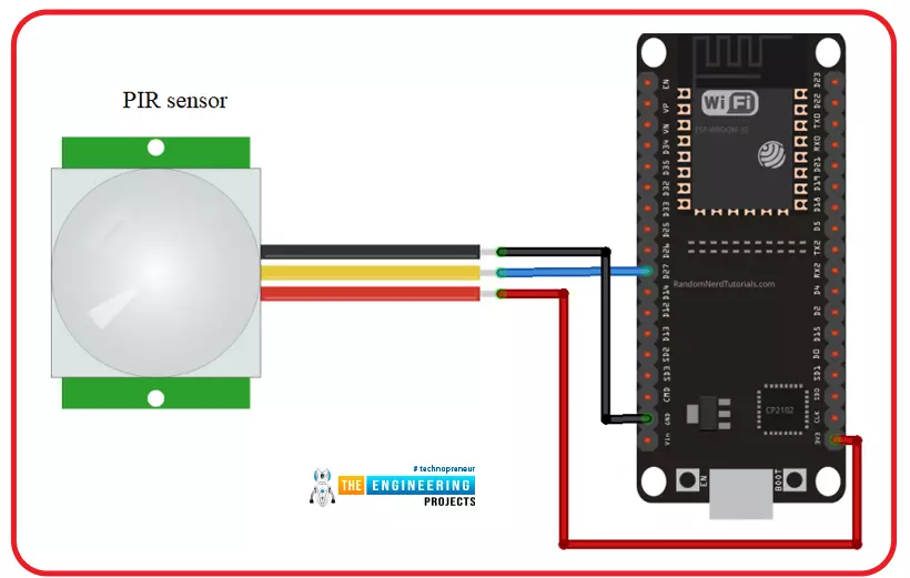
Espressif Systems created the ESP32 Wi-Fi chip series. The ESP32 module is equipped with a 32-bit Tensilica microcontroller, 2.4GHz Wi-Fi connectivity, an antenna, memory, and power management modules, and much more. All of these built-in features of this ESP32 module make it ideal for IoT applications.
Hello readers, I hope you all are doing great. In this tutorial, we will learn another application of ESP32 in the field of IoT (Internet of Things). We are using a PIR s ...
Hi Friends! Hope you’re well today. In this post, I’ll walk you through What is Edge Computing?
Edge computing is the extension of cloud computing. Cloud computing is used for data storage, data management, and data processing. While Edge Computing does serve the same purpose with one difference: edge processing is carried out near the edge of the network which means data is processed near the location where it’s produced instead of relying on the remote location of the cloud server.
Confused?
Don’t be.
We’ll touch on this further in this article.
Curious to know more about what is edge computing, the difference between edge computing and cloud computing, benefits, and applications?
Keep reading.
What is Edge Computing?
Edge computing is the process where data is processed near or at th ...
Hi guys! Hope you’re well today. In this post today, I’ll cover What is Industrial IoT (Internet of Things?)
IIoT is now a talk of mainstream conversation. This term has blown up in the past couple of years. Before we move further to describe IIoT, it is evident that industries are no longer dependent on the traditional production processes that happened to be costly and guaranteed no optimal results. Now companies are willing to incorporate automation in manufacturing and production processes. Smart systems, no doubt, are dangerous for the traditional labor workforce, but on the other hand, they create more opportunities for the people equipped with the latest business trends.
Curious to know more about Industrial IoT, how does it work, the difference between IoT and IIoT, examples of II ...
Welcome to the fourth lesson of this python course. Our previous session taught us how to utilize the print function in python, so we have a firm grasp of the terminology and the functions themselves. In this lesson, we'll cover a few more Python terms, such as:
Strings
Operators
Input function
Also, we'll build a simple program to print out an imagined dog so that we may better grasp how these concepts are employed. So, let's get started now.
Why do we need to understand these terms?
Programming is a lot like building a structure out of blocks. Even with just a few types of children's toy blocks and some time and imagination, you can build anything. Because we'll be utilizing these phrases all the time in programming, it's critical that you know what they mean and how to use th ...
Hello readers, we hope you all are doing great. Welcome to the 1st lecture of Section 4 in the ESP32 Programming Series. In this section, we will interface the ESP32 module with common Embedded modules(i.e. LCD, Keypad, RTC etc.).
In today's tutorial, we will interface ESP32 with a 16x2 LCD and will display data using both Data Mode and I2C Mode. LCD is the most commonly used embedded module in IoT Projects. It is used to display different types of data i.e. sensor readings, warning messages, notifications etc.
Before going forward, let's first have a look at what is LCD and How it works:
16x2 LCD Module
LCD(Liquid Crystal Display) is a type of electronic display module that is used in a wide variety of applications and devices such as calculators, computers, mobile phones, ...
Hello friends, I hope you all are doing great. In today's tutorial, we will have a look at the Common Mistakes to Avoid When Investing in Technology for Your Venture.
Tech tools can make or break a business in this day and age, regardless of the industry or niche a venture is in. As such, it’s vital to source the best possible technologies that will help you make your organization the best it can be and the most likely to reach its goals. As you invest in technology, it pays to avoid some common mistakes.
Mistake: Not Having a Plan
Many entrepreneurs have a detailed business plan they created when they began or bought their business, but they fail to plan much for technology. It’s essential to have a vision and strategy for your technological nee ...
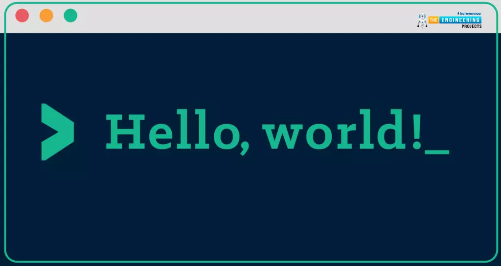
The "Hello, World!" program is a computer programming classic that has stood the test of time. For beginners, "Hello, World!" is a simple and full first program that introduces the basic syntax of programming languages and can be used to evaluate systems and programming environments.
The more you learn about Python, the more you may use it for your own purposes. Data analyst, application developer, or the ability to automate your work processes are all examples of jobs that can be automated.
This Python 3 tutorial will show you how to create a simple "Hello, World" program. Python's basic syntax and components include the following:
Variable-types
Data structures
Math operators
loops
Different function calls
Input and output functio ...
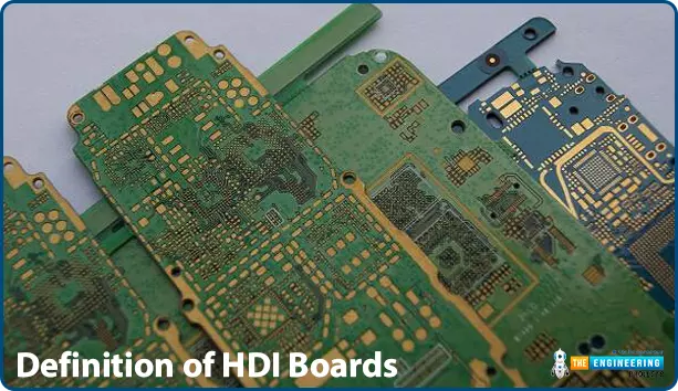
The printed circuit board is a type of plastic where electrical and electronic components lie, laminated and fixed. In modern days, there has been increasing in the complexity of electronic components and devices and this has also led to high demand for more complex PCBs that can make this achievable. This exclusive board that has been introduced in the market includes HDI, rigid-flex, Aluminium clad, buried and blind or even a blend of all the listed types.
There is a list of so many PCB types that a designer can choose for any type of electronic project ranging from single layer PCB to other complex types like the multilayered PCBs. In general, the simplest type of PCB contains copper tracks and interconnection between the elements and components on one side of the board. These types of ...
Hi friends, today we are going to explore mathematical computations in ladder logic. Like in any programing language you should find logic and mathematic computations, here in PLC programming you often need to process the input data that is collected from reading analog devices like temperature, level, flow et cetera. Then you need to run some calculations on this data to derive some other variables for deciding to run or stop some device or even to determine analog output to output to analog device i.e. valve or actuators. In the following sections, we are going to explore the mathematical functions and their input operators and outputs as well. Then we will show how to utilize such functions in ladder logic with simple examples and as usual enjoy practicing them thanks to the PLC simula ...