Hello readers, I hope you all are doing great. This is the second tutorial of the Raspberry Pi programming series. In our previous tutorial, we discussed the basic features and hardware architecture of Raspberry Pi Pico.
In this tutorial, we will discuss the various available development environments for programming the Raspberry Pi Pico. Later, in this tutorial, we will also discuss the installation of Visual Studio Code for Pi Pico programming.
Fig. Raspberry Pi Pico
RP2040 supports multiple programming languages like C/C++, Circuit python, and MicroPython cross-platform development environments. Raspberry Pi Pico module consists of a built-in UF2 bootloader enabling programs to be loaded by drag and drop and floating point routines are bake ...
Hello readers, I hope you all are doing great. This is the first tutorial of our Raspberry Pi programming series. In this tutorial, we are going to provide a brief description of the Raspberry Pi Pico module designed and developed by the Raspberry Pi organization itself. We will also discuss various features, memory, peripherals interfacing capabilities, hardware architecture, programming techniques etc.
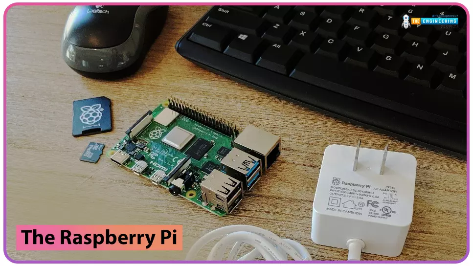
Before moving towards the detailed study of the Raspberry Pi Pico module, let’s first understand the traditional Raspberry Pi Computers.
What is Raspberry Pi?
Raspberry Pi is a single-board computer or a minicomputer. It was created with the goal of making computing knowledge more accessible to those who cannot afford laptops or desktop computers ...
to our new beginner’s course on Raspberry Pi. This course is appropriate for anyone using either a traditional Raspberry Pi board or the new Raspberry Pi 400 board that includes an integrated keyboard and display. Learning how to code, building robots, and doing plenty of other strange and exciting things are all possible with this low-cost computer setup. The Raspberry Pi can do everything a computer can do, from surfing the web to viewing movies and music, and playing video games.
Raspberry Pi is much more than a modern computer. It`s created to educate young people on how to program in languages such as Scratch and Python, and it comes with all of the major programming languages pre-installed. The world is in desperate need of programmers now ...
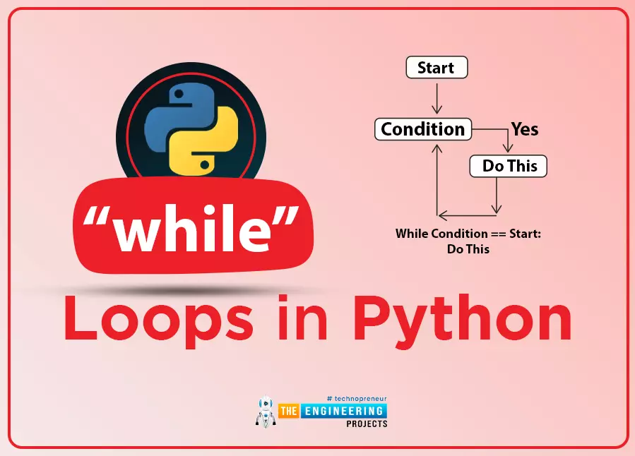
Welcome to the next lesson of our python programming class. In the last session, we looked at the use of If-else statements and created simple programs to demonstrate the concept. While loops are another type of conditional statement, and in this tutorial, we'll look at how they're used.
What will you learn?
In this article, you'll learn how to prematurely exit a while loop, a Python control structure for endless iteration. You will also learn how to write conditions in a single line to produce short and readable code.
Iteration in while loop
The term "iteration" refers to the practice of repeatedly running the same piece of code. A loop is a type of programming structure that implements iteration.
Bo ...
Internet of Things is a system of multiple inter-related computing devices. The factor ‘thing’ in IoT is designated to an entity capable of communicating data over a network (IOT), which can be a digital machine, sensor, human being, animals etc. Each component that is included in IoT network is assigned with an unique identity called UID and the ability to communicate data over IoT network without any external human or computer intervention.
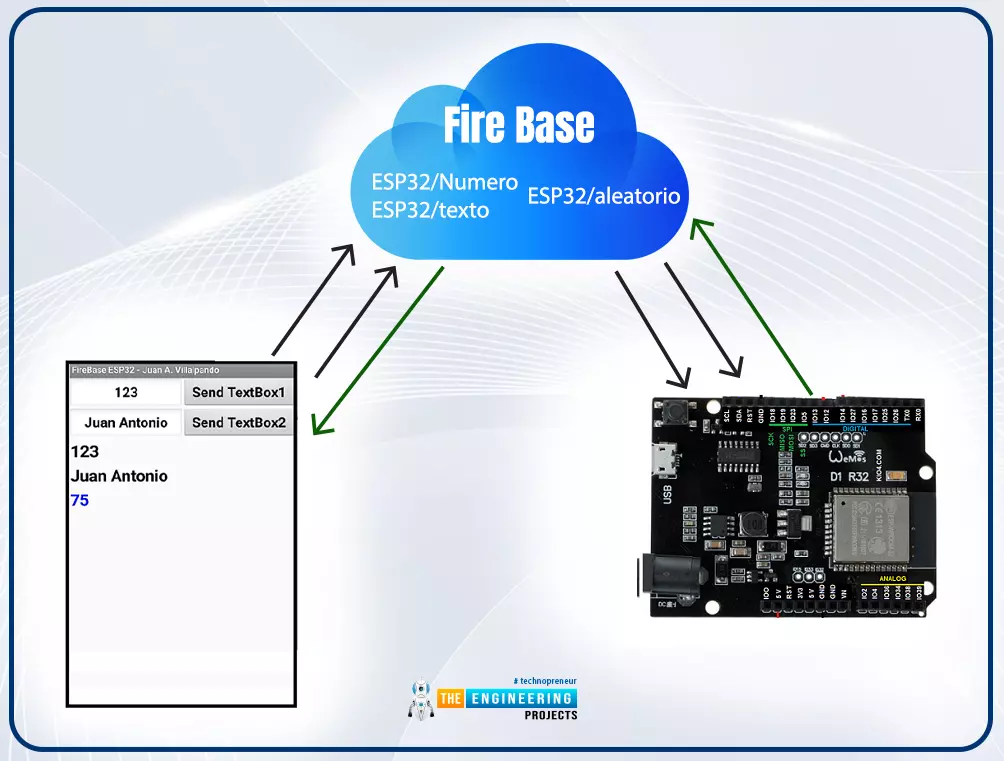
Hello readers, I hope you all are doing great. In our previous tutorial, we discussed how to upload data to Firebase Real-time Database using ESP32. In this tutorial, we will learn how to read the data stored on the Firebase Database with ESP32.
We can access the data stored in Firebase database from anywhere in the world, which makes this preferable ...
Welcome to the fifteenth chapter of this python course. Python lists and tuples were studied extensively in the last session, and we learned how to manipulate the data contained in these types of structures. You've only experienced sequential execution up to this point, where each statement is performed sequentially in the order they appear in the code.
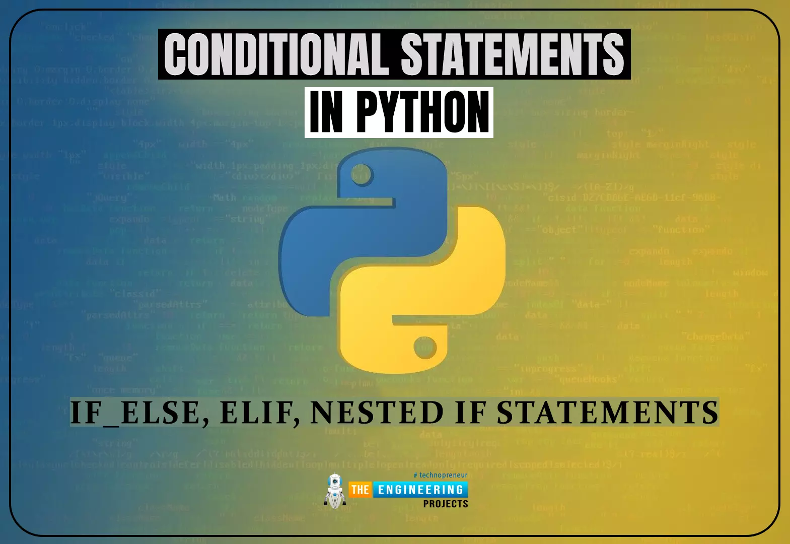
However, the real world is frequently more nuanced. Sometimes, a program must skip over certain statements, run a set of statements repetitively, or pick between other sets of statements to execute. This is called "conditional branching."
That's when control structures come into play, which controls the sequence in which statements in a program are executed.
What will you learn?
The if statement ...
Welcome to the fourteenth chapter of our python tutorial course. In the last lesson, we looked at sets and operations done to sets, including union and intersection. In this tutorial, we'll take a closer look at lists and tuples to see how they're used. Python's most versatile and useful data types are lists and tuples. A non-trivial Python application will nearly always have these.
What will you learn?
Lists and tuples have a number of significant features that you'll learn about. In this course, you'll understand the definitions and applications of these terms. By the time you're done, you'll know when and how to employ different Python object kinds.
What are lists?
In other words, Lists are similar t ...
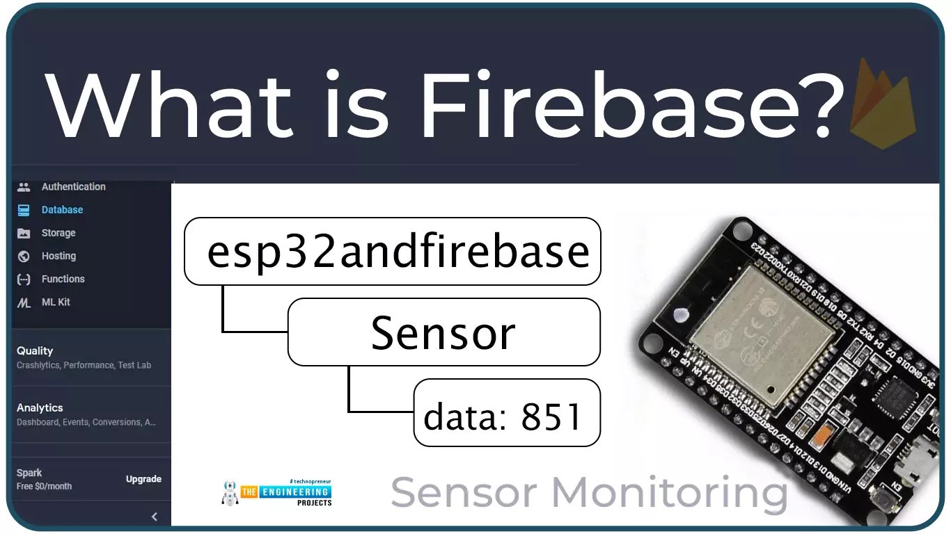
Hello readers, I hope you all are doing great. In this tutorial, we will learn how to access Firebase (a real-time database) to store and read values or data with ESP32.
It is Google’s mobile application development platform that can be used to can access, monitor and control ESP32 from anywhere in the world with its (firebase) real-time database.
What is Firebase?
Firebase real-time database is a development platform provided by Google which included multiple services to manage and authenticate data.
Firebase is basically a mobile and web app development platform I as works great with Android APIs) that includes features like firebase cloud, real-time data and Firebase authentication etc.
As per Firebase’s official documentation (https://firebase.google.com/docs/database), whenever a us ...
Hello readers, I hope you all are doing great. In this tutorial, we will learn how to interface the BMP280 sensor with the ES32 module to get temperature, pressure and altitude readings. Later, in this tutorial, we will also discuss how to upload these sensor readings to a web server.
BMP280
BMP280 or Barometric pressure sensor is a module used to measure temperature pressure and altitude. The small size and low power consumption feature of this sensor makes it feasible for battery-powered devices, GPS modules and mobile applications etc.
Fig. 1 BMP280 Sensor
The BMP280 is the product of BOSCH which is based on Bosch’s proven Piezo-resistive pressure sensor technology featured with high accuracy, long term stability, linearity and high EMC robus ...
Hello everyone. Today is a great day that we are going to put our focus on another type of PCB. So far in the previous articles, we have looked at high speed, metalcore, high density interconnect and the ceramic types of PCBs. In this article, we are going to introduce another type of PCB that might find great use in your day-to-day interaction with the printed circuit boards. it is very important for a designer to take note of how PCBs have evolved and how they have become an important aspect in the design of successful electronic devices. It has become hardly difficult to come across any time of an electronic device that does not involve the use of printed circuit boards.
In PCB boards you come across LEDs fixed in them, and due to the evolving w ...