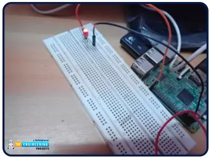
Hello friends, I hope you all are doing great. It's the 8th tutorial in our Raspberry Pi programming course. In the previous lectures, we interfaced LCD 16x2 and Keypad 4x4 with Raspberry Pi 4. In this chapter, we are not going to interface any external module with Pi, instead, we'll create a PWM signal in the raspberry pi using Python. Let's get started:
Components RequiredWe are going to use the below components in today's PWM project:
Raspberry Pi 4.
LED.
A resistor of 330 ohms.
Breadboard.
Jumper wires.Before going forward, let's first understand what is PWM:
What is PWM?
In PWM(Pulse Width Modulation), we simply turn on and off our power supply at regular intervals and thus ...
Hi Friends! Hope you’re well today. I welcome you on board. In this post today, I’ll walk you through Cloud Computing Services.
The requirement to process and store data varies from business to business. Some organizations can handle data in on-site data centers. They have a team of experts who handle IT infrastructure and install, maintain and upgrade hardware based on the availability of data. This approach is expensive, no doubt. Some companies, however, don’t accept this model. They prefer cloud computing which is the availability of on-demand IT infrastructure over the internet. This model sets them free from handling and managing on-site data centers, instead, everything is managed and controlled by the cloud service providers. End users only pay for the computing services they use. ...
Hello readers, I hope you all are doing great. In our previous tutorial, we discussed the installation procedure of Visual Studio Code for programming Raspberry Pi Pico.
We have already mentioned in our previous tutorials that RP2040 or Raspberry Pi Pico supports multiple programming languages like C/C++, Circuit python, MicroPython cross-platform development environments. Raspberry Pi Pico module consists of a built-in UF2 bootloader enabling programs to be loaded by drag and drop and floating-point routines are baked into the chip to achieve ultra-fast performance.
There are multiple development environments to program a Raspberry Pi Pico board like Visual Studio Code, Thonny Python IDE, Arduino IDE etc.
So, in this tutorial, we will learn how t ...
The eCommerce industry, which has already experienced year-over-growth for the past five years, gained a monumental boost after the pandemic made online shopping mainstream. Today, there are more than 20 million eCommerce businesses operating worldwide, and new companies open shops every day.
The majority of these companies need skilled developers and engineers to build safe and robust eCommerce sites to house their businesses. If you are interested in specializing in eCommerce development, you would be remiss to ignore the advantages and disadvantages of each payment gateway option.
Payment gateways allow online customers to purchase products seamlessly and securely. However, they are not all created equal. As an engineer or site developer, you s ...
Hi Guys! Glad to have you on board. Thank you for clicking this read. In this post today, I’ll walk you through the Types of Internet of Things (IoT).
IoT has been around for a while and has started making the headlines over the past couple of years. Some people experience IoT in their everyday life but are not aware of what it actually is. When physical objects “things” interact with the digital world, IoT is born. In simple words, it’s the network of connected devices integrated with sensors that work to exchange and share data over the internet. It is a rapidly growing technology with more than 18 billion connected IoT devices today and with the inception and boost of 5G technology this figure is expected to touch 125 billion by 2030. Experts say we may witness the stage when everythin ...
Workflow automation is a topic that has been on the rise for many years now. With more and more companies switching to new technologies, this will become a bigger problem. It's time we take it seriously and find ways to improve employee productivity through workflow automation.
As you'll learn in this article, there are various benefits of automating the workflows that can help you achieve higher levels of success!
What is Workflow Automation, and Why Is It Important?
Workflow automation uses technology to improve or replace manual work tasks. Automation can save time and money by reducing or eliminating the need for human intervention in repetitive or time-consuming tasks and thus reducing workforce management.
Most businesses can benefit from w ...
Hi there! Happy to see you around. Thank you for clicking this read. In this post today, I’ll cover how cloud computing can benefit small businesses.
Cloud computing is the new normal. Many small and medium-sized businesses use cloud computing to handle and store a large amount of data. But what does cloud computing mean? Even if they are using it, some people don’t understand this term. Don’t worry. I’m here to make it clear for you.
Cloud computing is the availability of computing resources over the internet; these resources include databases, servers, storage, processing power, and more. In simple words, it’s the process of storing, hosting, managing, and processing data on third-party hardware over the internet. The common third-party service providers include AWS (Amazon Web Service) ...
This is the third tutorial in our Raspberry Pi programming course. In the previous chapter, we learned how to install Raspbian on our Raspberry Pi mini-computer. In this chapter, we'll learn how to use a VNC server to remotely control and see its desktop from our computer.
What is VNC?
Computing over a network is known as "virtual network computing," or "VNC." To remotely control another computer, you can use this screen-sharing technology, which works on all major operating systems. As a result, a remote user can interact with a computer's display (screen, keyboard, and mouse) as if they were sitting right in front of it.
VNC takes advantage of the client/server concept. Rather than installing a VNC s ...
Welcome to the second chapter of our beginner's course on the Raspberry Pi. In the previous tutorial, we learned about the components of this little computer. We also considered its uses, as well as the most important advantages and disadvantages. Let's get started with setting up our little computer to run the Raspbian operating system in this lesson.
How to Install Raspbian using an imager
The next step is to make sure you have your board and SD card. The Raspberry Pi has an operating system because it is a full computer. For those who prefer a GUI desktop experience, a headless mode is still an option. Most people use Raspbian, a Debian-based operating system tailored specifically for the Raspberry Pi. However, there are other options. An exce ...
Hello readers, I hope you all are doing great. This is the second tutorial of the Raspberry Pi programming series. In our previous tutorial, we discussed the basic features and hardware architecture of Raspberry Pi Pico.
In this tutorial, we will discuss the various available development environments for programming the Raspberry Pi Pico. Later, in this tutorial, we will also discuss the installation of Visual Studio Code for Pi Pico programming.
Fig. Raspberry Pi Pico
RP2040 supports multiple programming languages like C/C++, Circuit python, and MicroPython cross-platform development environments. Raspberry Pi Pico module consists of a built-in UF2 bootloader enabling programs to be loaded by drag and drop and floating point routines are bake ...