Rather than investing in new electronic equipment, we will use an Arduino board and some basic components to measure the capacitance. To make this project, we should have some working knowledge about the capacitor. Here, we will not discuss the in-depth working of capacitors, but we will talk briefly so that it would be easy to understand the working principle of our project.
The capacitor is an electronic component that basically stores the energy when applied to an electric field. It has two parallel terminals connected by two parallel conducting plates separated by a dielectric material. Dielectric materials are electrical insulators(resist to pass the current) that can be polarised by applying an electric field. When we connect a battery with the capacitor then due to potential difference, the electric field is created between two oppositely charged plates of the capacitor and this way the capacitor stores the energy.
| Where To Buy? | ||||
|---|---|---|---|---|
| No. | Components | Distributor | Link To Buy | |
| 1 | Capacitor | Amazon | Buy Now | |
| 2 | Resistor | Amazon | Buy Now | |
| 3 | LCD 16x2 | Amazon | Buy Now | |
| 4 | Arduino Uno | Amazon | Buy Now | |
To make this project, we will need some software to install. As we will make our project in the simulation, so for that we will install Proteus simulation software and for coding, we will use the Arduino IDE.
A brief about Proteus, it is a tool used for simulation and design of electronic circuits. Here we can design different types of electronic circuits and run the simulation. Although Proteus has a very big database for electronic components, still we need to install some libraries which we will use in this project.
You can download this whole project for example Proteus Simulation and Arduino Code, by tapping the below button:
Capacitance Measurement using ArduinoIn this project, we will use the following components-
Now let's talk about the working of this project. The capacitance of any capacitor is the amount of charge that is stored in that capacitor and its unit is Faraday (F). To measure the capacitance, we will use some basic properties of the capacitor.
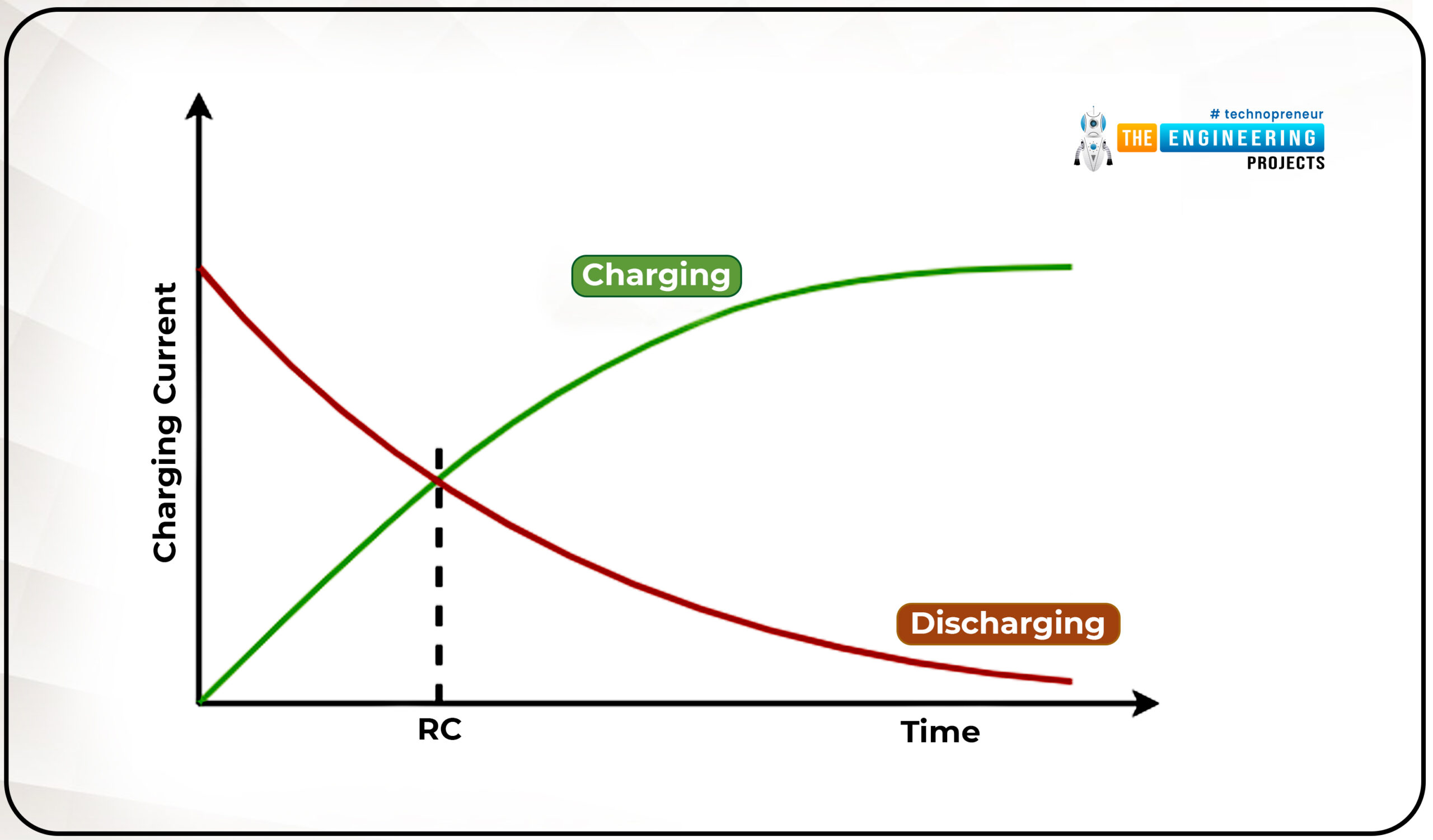
So when we connect a power supply with a resistor across the terminals of a capacitor, it will take a certain amount of time to fully charge. And when we connect any discharging resistor as a load across it, then it will take a certain amount of time to fully discharge. And this charging and discharging time will be proportional to the capacitance of the capacitor and the charging resistor in the RC circuit.
We will use the time constant formula for the calculation of capacitance. The time constant of any capacitor is known as the time taken by the capacitor to charge 63 percent of applied voltage or the time taken by the capacitor to discharge to 33 percent of stored voltage.
Here,
T (Tau) = Time constant(Seconds)
R = Resistance (Ohms)
C= Capacitance (Farads)
Using the above principle, we will charge the capacitor using a resistor to reach the charge of the capacitor to 63 percent of applied voltage and we will measure the time taken by the capacitor to reach that point. As we know the resistor’s value and time constant, using these two, we can calculate the capacitance:
Note-Whenever uploading the code on the Arduino UNO, disconnect any wire which is connected to Rx(D0) and Tx(D1) pins, otherwise, it will give an error while uploading the code.
Now, we have a list of all the required components. Let's start connecting them.
While working on the real components, make sure you have connected the backlight of the LCD module and set the contrast properly otherwise nothing will be visible on the LCD module.
I hope we have covered all the points related to this project such as circuit diagrams, codes, and working simulation. And I think this will be a very useful project for your daily tinker life. Please let us know if you face any difficulties while making this project in the comment section below.
We will be happy to hear if you will make this project used in your projects.
Thanks for reading this article. All the best and see you in the next project.
We are familiar with multiple features of the ESP32 module. Like Wi-Fi capabilities, classic Bluetooth, Bluetooth low energy (BLE), inbuilt sensors etc.
Hello readers, I hope you all are doing great. We have already mentioned in our previous tutorials that, ESP32 is also featured with a Dual-Core Processor. Which provides better performance and efficiency.
In this tutorial, we will learn how to use ESP32’s dual cores. ESP32 has two (32-bit each) Tensilica Xtensa LX6 microprocessors namely, core0 and core1 which makes it a powerful dual-core microcontroller and hence stands apart from its predecessors.
When we compile and upload a code using Arduino IDE, we do not have to worry about which core executes the code. It just runs.
Fig. 1 ESP32 dual-core processor
| Where To Buy? | ||||
|---|---|---|---|---|
| No. | Components | Distributor | Link To Buy | |
| 1 | ESP32 | Amazon | Buy Now | |
A FreeRTOS (real-time operating system) firmware is already available in the ESP32 module. FreeRTOS is helpful in improving the system performance and managing the resources of the module. FreeRTOS allows users to handle several tasks like measuring sensor readings, making a network request, controlling motor speed etc. all of them run simultaneously and independently.
FreeRTOS offers multiple APIs for different applications. Those APIs can be used to create tasks and make them run on different cores. You need to create tasks to assign a particular part of code to a specific core. You can also prioritize that on which core the code will run. Priority value starts with level_0.
Whenever we run a code on Arduino IDE, it runs on core_1 by default.
There is a function you can use to check on which core the code is running on.
xPortGetCoreID()
Run the following code in Arduino IDE:
void setup(){
Serial.begin(115200);
Serial.print( " setup() is running on: Core_" );
Serial.println( xPortGetCoreID() );
delay(1000);
}
void loop()
{
Serial.print( " loop() is running on: Core_" );
Serial.println( xPortGetCoreID() );
delay(1000);
}
Fig. 2 Serial Monitor
From the results on the serial monitor, you can see that both setup() function and loop() function are running on core_1.
Fig. 3
This function takes seven arguments:
Fig. 4
For example, we have created a function named task_code(). Inside the task_code() function a for(;;) loop is used which will create an infinite loop. All the instructions to be given for a particular core to perform a particular task like led blinking, sensor readings etc. will be written inside this for(;;) loop.
Fig. 5
You can use the function vTaskDelete() during the code execution to delete a task. This function takes the task handle (task) as an argument.
In this code we will use two LEDs to be processed by different core.
TaskHandle_t task1;
TaskHandle_t task2;
// Assign GPIOs pins to LEDs
const int led1 = LED_BUILTIN;
const int led2 = 25;
void setup() {
Serial.begin(115200 );
pinMode( led1, OUTPUT );
pinMode( led2, OUTPUT );
//create a task that will be executed in the Task1code() function, with priority 1 and executed on core 0
xTaskCreatePinnedToCore(task_1code, // Task function.
"Task1", // name of task.
10000, // Stack size of task
NULL, // parameter of the task
1, // priority of the task
&task1, // Task handle to keep track of created task
1); // pin task to core 1
delay(1000);
//create a task that will be executed in the Task2code() function, with priority 1 and executed on core 1
xTaskCreatePinnedToCore(task_2code, //Task function.
"task2", //name of task.
10000, //Stack size of task
NULL, //parameter of the task
1, //priority of the task
&task2, //Task handle to keep track of created task
0); //pin task to core 0
delay(1000);
}
//task_1code: blinks an LED every 1000 ms
void task_1code( void * pvParameters ){
Serial.print( "task1 running on: core " );
Serial.println( xPortGetCoreID() );
for(;;)
{
digitalWrite( led1, HIGH);
delay(1000);
digitalWrite(led1, LOW);
delay(1000);
}
}
//task_2code: blinks an LED every 500 ms
void task_2code( void * pvParameters )
{
Serial.print( "task2 running on: core " );
Serial.println(xPortGetCoreID() );
for(;;){
digitalWrite(led2, HIGH );
delay(500);
digitalWrite(led2, LOW );
delay(500);
}
}
void loop(){
Serial.print( " loop() is running on: Core " );
Serial.println( xPortGetCoreID() );
delay(1000);
}
Fig. 6
Fig. 7
Fig. 8 setup() function
Fig. 9
Fig. 10
Fig. 11
Fig. 12
Fig. 13 loop function
Components required:
Fig. 14 connecting LED with ESP32
Fig. 15 Results on the serial monitor
This concludes the tutorial. We hope you found this helpful and also hope to see you soon with a new tutorial on ESP32.
Hello readers, I hope you all are doing great. In our previous tutorial, we learnt how to make HTTP POST from ESP32 to the IFTTT server.
In this tutorial, we will learn about another application of the ESP32 module in the field of IoT (Internet of Things). We can publish multiple sensor readings from ESP32 to Google sheets via the IFTTT web service.
IFTTT is used as a third-party web service to integrate Google sheets with ESP32.
Fig. 1
| Where To Buy? | ||||
|---|---|---|---|---|
| No. | Components | Distributor | Link To Buy | |
| 1 | ESP32 | Amazon | Buy Now | |
We are going to create an applet (on the IFTTT server) that is responsible to integrate the Webhooks and Google Sheets services.
While operating with the IFTTT server there are some services/utilities that we are going to deal with like Applets and Webhooks. Before getting started with the project, let’s first introduce you to those terms:
An Applet is a small application or a utility program, which is used for one or a few simple functions. It connects two or more devices or apps together. An applet provides integration between two devices or services to enable some functionality that those devices or services cannot do alone or on their own. An applet consists of actions and triggers.
Fig. 2
Fig. 3: Creating an Applet
Fig. 4: “If This”
Fig. 5: Search and Select Webhooks
Fig. 6: Receive a Web Request
Fig. 7: Create Trigger
Fig. 8: Then That
Fig. 9: Google Sheets
Fig. 10: Select an Action
Fig. 11: Connect to Google Sheets Service
Fig. 12: Allow IFTTT Service to Access Files of your Google Drive
Fig. 13: Complete Action Fields
Fig. 14: Applet Successfully Created
Before interfacing the IFTTT service (applet) with ESP32, let us test the applet whether it is created successfully or not.
Fig. 15
Fig. 16: Test your Applet
Fig. 17: IFTTT Folder in Google Drive
No external components are required as we are using the ESP32’s inbuilt sensors to take the readings.
Let’s have an overview of the project before writing the Arduino code:
#include <WiFi.h>
// Replace with your SSID and Password
const char* ssid = "SSID";
const char* password = "Password";
// Replace with your unique IFTTT URL resource
const char* serverName = "https://maker.ifttt.com/trigger/replace_this_with_eventName/with/key/replace_this_with_your_unique_key ";
// Maker Webhooks IFTTT
const char* server="maker.ifttt.com";
//----Timer for sleep
uint64_t uS_TO_S_FACTOR = 1000000; // Conversion factor for micro seconds to seconds
uint64_t TIME_TO_SLEEP = 900; //sleep for 15 minutes
void setup()
{
Serial.begin(115200);
delay(100);
Serial.print("Connecting to: ");
Serial.print(ssid);
WiFi.begin(ssid, password);
int timeout = 10 * 4; // 10 seconds
while( WiFi.status() != WL_CONNECTED && ( timeout-- > 0) )
{
delay(200);
Serial.print(".");
}
Serial.println(" ");
if(WiFi.status() != WL_CONNECTED )
{
Serial.println(" Failed to connect, going back to sleep ");
}
Serial.print("WiFi connected in: ");
Serial.print(millis());
Serial.print(", IP address: ");
Serial.println(WiFi.localIP());
makeIFTTTRequest();
// enable timer deep sleep
esp_sleep_enable_timer_wakeup(TIME_TO_SLEEP * uS_TO_S_FACTOR);
Serial.println("Going to sleep now");
esp_deep_sleep_start(); // start deep sleep for 900 seconds (15 minutes)
}
void loop()
{
// sleeping so wont get here
}
void makeIFTTTRequest()
{
Serial.print("Connecting to ");
Serial.print(server);
WiFiClient client;
int retries = 5;
while(!!!client.connect(server, 80) && (retries-- > 0))
{
Serial.print(".");
}
Serial.println();
if(!!!client.connected())
{
Serial.println(" Failed to connect... ");
}
Serial.print(" Request server: ");
Serial.println( serverName );
// Hall sensor values
String jsonObject = String("{\"value1\":\"") +
hallRead() +
"\",\"value2\":\"" + hallRead()
+ "\",\"value3\":\"" +
hallRead() + "\"}";
client.println(String("POST ") + serverName + " HTTP/1.1");
client.println(String("Host: ") + server);
client.println("Connection: close\r\nContent-Type: application/json");
client.print("Content-Length: ");
client.println(jsonObject.length());
client.println();
client.println(jsonObject);
int timeout = 5 * 10; // 5 seconds
while(!!!client.available() && (timeout-- > 0)){
delay(100);
}
if(!!!client.available()) {
Serial.println("No response...");
}
while(client.available()){
Serial.write(client.read());
}
Serial.println("\nclosing connection");
client.stop();
}
Fig. 18: Library Files
Fig. 19: Network Credentials
Fig. 20
Fig. 21
Note: The ESP32 sleep time should not be very short. A very short sleep time can result in the exceeded limit of requests imposed by the IFTTT service.
Fig. 22: Timer
Fig. 23: Serial Monitor
Fig. 24: Wi-Fi
Fig. 25
Fig. 26
Fig. 27
Fig. 28
Fig. 29
Fig. 30
Fig. 31: Hall Sensor Readings on Google Sheets
Fig. 32: Serial Monitor
This concludes the tutorial. I hope you found this of some help and also to see you soon with the new tutorial on ESP32.
New workers are three times more likely to sustain an injury in their first month than workers with a year's experience on the job. By improving employee training and tailoring programs to the demands of each individual role, you can better minimize the risk of accident and injury (a lab employee, for instance, requires vastly different training to an industrial line worker). In fact, OSHA advises implementing different plans for five key areas in order to form a comprehensive health and safety approach: hazard assessment; hazard mitigation; hazard prevention; electrical safety; and safety training. Additionally, it’s important to provide refresher training sessions on a regular basis. Never make health and safety training a one-time occurrence. By reiterating health and safety information and advice throughout the year, you can ensure workers maintain awareness of best practices.
A health and safety management system is essential for identifying and resolving workplace hazards and protecting workers, as well as improving overall operational performance. In fact, it can reduce total costs arising from occupational injuries by at least 20-40%. To devise your system, OSHA recommends first identifying any health and safety issues, including, risks and hazards, management system deficiencies, and opportunities for improvement, and then prioritizing those issues. You can then determine the goals of your health and safety management system in order to maximize workplace safety and minimize risks. If an employee does sustain an injury while on the job, it’s important they inform themselves of their legal rights. Filing a lawsuit for personal injury damages can help injured employees secure financial compensation to cover the cost of medical bills and lose income, Aaron Allison Law explains.
By incentivizing compliance, you have a better chance of ensuring your employees adhere to health and safety standards. Industrial workplaces often involve high-risk activities dealing with heavy machinery, electrical tools, and toxic chemicals on a daily basis. As such, employees can easily become too comfortable and lax, which results in potential injury or death. Incentivizing compliance could, for example, involve rewarding employees or managers when they achieve pre-set health and safety goals. Similarly, examples of non-compliance with rules and guidelines should also be corrected.
Health and safety should be a priority in all industrial workplaces. By improving employee training, implementing a health and safety management system, and incentivizing compliance, you can keep your workplace as safe as possible for employees.
ESP32 is a powerful chip for Internet of Things applications. This tutorial is also based on another ESP32 application in the field of IoT.
Hello readers, I hope you all are doing great. In the previous tutorial, we learned how to send sensor readings from ESP32 to the cloud (ThingSpeak webserver).
In this tutorial, we will learn to send HTTP POST requests from the ESP32 board to ThingSpeak and IFTTT APIs.
| Where To Buy? | ||||
|---|---|---|---|---|
| No. | Components | Distributor | Link To Buy | |
| 1 | ESP32 | Amazon | Buy Now | |
Fig. 1 Hypertext Transfer Protocol
HTTP stands for hypertext transfer control and it is a protocol for transferring data between a web client and a web server. Hyper text transfer protocol was invented alongside HTML (Hypertext markup language) to create the first interactive, text-based web browser: the original www or World Wide Web.
Server and client communication process over HTTP:
Fig. 2 HTTP POST Request
Hypertext transfer protocol uses particular request methods to execute various tasks. Two mostly used HTTP request methods are: HTTP GET request and HTTP POST request.
HTTP GET request is generated to request data from a specific resource and the HTTP POST request method is used to send data from the client device to the server to create or update resources.
In this tutorial, we will demonstrate only the HTTP POST method with ThingSpeak and IFTTT web services.
Features of the HTTP POST request:
IFTT stands for If This Then That. It is a free web service for making different services like email, weather services, Twitter etc to connect.
IFTTT means if a service is triggered, other IFTTT services will take action.
Fig. 3 IFTTT
IFTTT acts as a bridge between ESP32 and other web services. Some of the tasks the ESP32 board can perform with the IFTTT API service are:
IFTTT comprises Applets and Applets further contains two IFTTT services namely trigger and action.
You can use the applets created by a company or can also create your own applet. To use the IFTTT applet with ESP32, we need to create an applet by ourselves. Such applet will contain Webhooks service to interact directly with ESP32 and other services that you want to use like email, Twitter service etc.
There are cases while using ESP32 with the IFTTT: either ESP32 will trigger the IFTTT to do some task or the IFTTT triggers ESP32 to do some task.
Steps to trigger IFTTT via ESP32
Enter the following link in the web browser: https://ifttt.com
Fig. 4 Creating an Applet
Fig. 5 ” If This”
Fig. 6 Search and Select Webhooks
Fig. 7 Receive a Web Request
Fig. 8 Create Trigger
Fig. 9 Then that
Fig. 10 Selecting a Service
Fig. 11
Fig. 12 To Trigger an Event
Fig. 13 Event Successfully Triggered
#include <WiFi.h>
#include <HTTPClient.h>
//---------Netwrok Credentials
const char* ssid = "SSID";
const char* password = "Password";
const char* serverName = "http://maker.ifttt.com/trigger/ESP32_test/with/key/Enter you API key";
unsigned long lastTime = 0;
unsigned long timerDelay = 15000;
void setup()
{
Serial.begin(115200);
WiFi.begin(ssid, password);
Serial.println("Connecting");
while(WiFi.status() != WL_CONNECTED)
{
delay(500);
Serial.print(".");
}
Serial.println("");
Serial.print("Connected to WiFi network with IP Address: ");
Serial.println(WiFi.localIP());
// Random seed is a number used to initialize a pseudorandom number generator
randomSeed(hallRead());
}
Void Loop()
//Send an HTTP POST request after every 15 seconds
if ((millis() - lastTime) > timerDelay)
{
//Check WiFi connection status
if(WiFi.status()== WL_CONNECTED)
{
WiFiClient client;
HTTPClient http;
// Your Domain name with URL path or IP address with path
http.begin(client, serverName);
// Specify content-type header
http.addHeader("Content-Type", "application/x-www-form-urlencoded");
// Data to send with HTTP POST
String httpRequestData = "value1=" + String(random(25)) + "&value2=" + String(random(25))+ "&value3=" + String(random(25));
// Send HTTP POST request
int httpResponseCode = http.POST(httpRequestData);
/*
// If you need an HTTP request with a content type: application/json, use the following:
http.addHeader("Content-Type", "application/json");
// JSON data to send with HTTP POST
String httpRequestData = "{\"value1\":\"" + String(random(40)) + "\",\"value2\":\"" + String(random(40)) + "\",\"value3\":\"" + String(random(40)) + "\"}";
// Send HTTP POST request
int httpResponseCode = http.POST(httpRequestData);
*/
Serial.print("HTTP Response code: ");
Serial.println(httpResponseCode);
Serial.println("successfully conected to host");
// Free resources
http.end();
}
else
{
Serial.println("WiFi Disconnected");
}
lastTime = millis();
}
}
Fig. Libraries
Fig. Network Credentials
Fig.
Fig.
Fig.
Fig.
Fig
Fig.
Fig.
Fig.
Fig. 14 Serial Monitor
Fig. 15 View Activity
Fig. 16 Received data.
Fig. 17 Email Received from IFTTT Server
We have already posted an article on sending sensor readings from ESP32 to ThingSpeak. In this article, we will learn how to send HTTP POST requests from ESP32 to send JSON data to the ThigSpeak server.
ThingSpeak is a web service operated by MathWorks where we can send sensor readings/data to the cloud. We can also visualize and act on the data (calculate the data) posted by the devices to ThingSpeak. The data can be stored in either private or public channels.
Steps to be followed to access ThingSpeak API:
Fig. 18 Getting Started for Free
Fig. 19 Create New Account
Fig. 20 MathWorks Sign in
Fig. 21 New Channel
Fig. 22 Create a New Channel
//-----------Libraries
#include <WiFi.h>
#include <HTTPClient.h>
//-----------Network Credentials
const char* ssid = "replace with your network SSID";
const char* password = "replace with netwrok password";
// Domain Name with full URL Path for HTTP POST Request
const char* serverName = "http://api.thingspeak.com/update";
// Service API Key
String apiKey = "Write API Key";
unsigned long lastTime = 0;
unsigned long timerDelay = 5000; //to add delay of 5sec
void setup()
{
Serial.begin(115200);
WiFi.begin(ssid, password); //initialize ESP32 wifi module
Serial.println("Connecting");
while(WiFi.status() != WL_CONNECTED)
{
delay(500);
Serial.print(".");
}
Serial.println("");
Serial.print("Connected to WiFi network with IP Address: ");
Serial.println(WiFi.localIP());
Serial.println("Timer set to 10 seconds (timerDelay variable), it will take 10 seconds before publishing the first reading.");
// Random seed is a number used to initialize a pseudorandom number generator
randomSeed(analogRead(25));
}
void loop()
{
//Send an HTTP POST request after every 5 seconds
if ((millis() - lastTime) > timerDelay)
{
//Check the WiFi connection status
if(WiFi.status()== WL_CONNECTED)
{
WiFiClient client;
HTTPClient http;
http.begin( client, serverName );
http.addHeader("Content-Type", "application/json");
String httpRequestData = "{\"api_key\":\"" + apiKey +
"\",\"field1\":\"" +
String(random(30)) + "\"}";
int httpResponseCode = http.POST(httpRequestData);
Serial.print("HTTP Response code: ");
Serial.println(httpResponseCode);
// Free resources
http.end();
}
else {
Serial.println("WiFi Disconnected");
}
lastTime = millis();
}
}
Fig.
Fig.
Fig.
Fig. : data (JSON) Chart on ThingSpeak
This concludes the tutorial. I hope you found this of some help and also to see you soon with the new tutorial on ESP32.
HCI is a great way to reduce operating costs and simplify IT by using a single virtual environment to combine, compute, storage and networking. This virtual-box solution is flexible and affordable enough, allowing even smaller companies and startups to purchase HCI architecture to connect and interact with their remote workers, branch offices, and IoT applications.
According to researchers, the global HCI market will continue to grow at a steady pace during the next five years. Increasing customer demand and rapid adoption of SaaS and other cloud-based solutions due to the changes in daily operations of most businesses caused by the Covid-19 pandemic has brought HCI into the spotlight. More and more vendors are offering hyperconverged solutions, both for cloud and on-premise infrastructures.
According to experts, the HCI market was valued at an impressive $7.34 billion in 2020. It's predicted to surpass the $10 billion mark by 2025. Backup and recovery solutions and performance-enhancing environments remain the main drivers of market growth. Other niches where HCI solutions are popular include VM farms, desktop virtualization software, and database management.
Server providers and other IT vendors are divided on the issue of HCI. While some of them seem to have exited the HCI market completely, others, including even a few hardware vendors, have doubled their efforts, focusing on selling software-only products.
Hyperconverged infrastructure fits seamlessly with Edge computing. Even smaller companies have to rely on Edge if they have branch offices or operate in remote locations. Industries like retail and banking use Edge as their default option. Since HCI removes the need for separate storage and networking devices, combining Edge with HCI creates natural synergy. Connecting thin clients and VDI workstations to the company's data center running on HCI improves the systems' reliability and makes it harder to breach from the outside. From the business point of view, partnering with a single HCI vendor instead of several hardware providers leads to cost reduction and better control and maintenance. HCI solutions consume less power and take up less space than their standard hardware counterparts.
Adoption of high-speed mobile networks like 5G will lead to further growth of Edge data centers using HCI. Enterprise data centers will either switch to this new business model or will provide HCI solutions alongside their traditional IT silos. In short, the HCI will continue to co-evolve alongside Edge, expanding from the niche of serving remote office environments to other businesses that look to cut costs, reduce storage capacity and benefit from centralized management of resources that HCI offers.
When it comes to IT infrastructure, the hybrid cloud has become the default option for most companies. Hyperconverged infrastructure can serve as the backbone of the hybrid- and multi-cloud platforms. Since HCI runs on widely-used x86 infrastructure and doesn't require tweaking and overhauling, cloud service providers switch from traditional storage/compute/network silos to hyperconverged alternatives.
Major players like Dell and Amazon are rapidly moving into the HCI niche. The new Dell Technologies Cloud runs on the VxRail platform, which is one of the HCI market leaders. AWS now offers Nutanix's hyperconverged infrastructure available as a service. Microsoft has come up with Azure Stack HCI, a powerful solution for hybrid clouds.
Hyperconverged infrastructure can become a promising alternative to popular public clouds like AWS or Microsoft Azure. The biggest selling points of HCI are its ability to scale, reduced costs, better performance, and control.
As mentioned previously, backup and data recovery remain the main market driver for HCI adoption. Due to the increasing number of cyberattacks, infrastructure security becomes one of the primary concerns for most companies. HCI allows to backup data on the fly, creating healthy redundancy. It's a cheaper solution since it doesn't require third-party solutions for data backup and disaster recovery. It also brings down costs associated with storage requirements, making hyperconverged infrastructure the most affordable and attractive option for backup and disaster recovery on the market right now.
Hyperconverged infrastructure will see increased adoption both by enterprise-level companies and data centers. It has found its natural synergy with Edge computing. The need for increased security will accelerate HCI adoption in the niche of backup and disaster recovery. The popularity of hybrid cloud solutions will also increase the number of companies using HCI for their IT needs.
Hello friends! I hope you all had a great start to the new year.
In our first lecture, we had looked at the MATLAB prompt and also learned how to enter a few basic commands that use math operations. This also allowed us to use the MATLAB prompt as an advanced calculator. Today we will look at the various MATLAB keywords, and a few more basic commands and MATLAB functions, that will help us keep the prompt window organized and help in mathematical calculations. We are also going to get familiar with MATLAB’s interface and the various windows. We will also write our first user-defined MATLAB functions.
Like any programming language, MATLAB has its own set of keywords that are the basic building blocks of MATLAB. These 20 building blocks can be called by simply typing ‘iskeyword’ in the MATLAB prompt.
The list of 21 MATLAB keywords obtained as a result of running this command is as follows:
To test if the word while is a MATLAB keyword, we run the command
iskeyword(‘while’)
The output ‘1’ is saying that the result is ‘True’, and therefore, ‘while’ is indeed a keyword.
‘logical’ in the output refers to the fact that this output is a datatype of the type ‘logical’. Other data types include ‘uint8’, ‘char’ and so on and we will study these in more detail in the next lecture.
Apart from the basic arithmetic functions, MATLAB also supports relational operators, represented by symbols and the corresponding functions which look as follows:
Here, we create a variable ‘a’ which stores the value 1. The various comparison operators inside MATLAB used here, will give an output ‘1’ or ‘0’ which will mean ‘True’ or ‘False’ with respect to a particular statement.
Apart from these basic building blocks, MATLAB engineers have made available, a huge library of functions for various advanced purposes, that have been written using the basic MATLAB keywords only.
We had seen previously that the double arrowed (‘>>’) MATLAB prompt is always willing to accept command inputs from the user. Notice the ‘’ to the left of the MATLAB prompt, with a downward facing arrow. Clicking this downward facing arrow allows us to access the various in-built MATLAB functions including the functions from the various installed toolboxes. You can access the entire list of in-built MATLAB functions, including the trigonometric functions or the exponents, logarithms, etc.
Here are a few commands that we recommend you to try that make use of these functions:
A = [1,2,3,4];
B = sin(A);
X = 1:0.1:10;
Y = linspace(1,10,100);
clc
clear all
quit
Notice that while creating a matrix of numbers, we always use the square braces ‘[]’ as in the first line, whereas, the input to a function is always given with round brace ‘()’ as in the second line.
We can also create an ordered matrix of numbers separated by a fixed difference by using the syntax start:increment:end, as in the third command.
Alternatively, if we need to have exactly 100 equally separated numbers between a start and and end value, we can use the ‘linspace’ command.
Finally, whatever results have been output by the MATLAB response in the command window can be erased by using the ‘clc’ command which stands for ‘clear console’, and all the previously stored MATLAB variables can be erased with the ‘clear all’ command.
To exit MATLAB directly from the prompt, you can use the ‘quit’ command.
In the next section, let us get ourselves familiarized with the MATLAB environment.
A typical MATLAB work environment looks as follows. We will discuss the various windows in detail:
When you open MATLAB on your desktop, the following top menu is visible. Clicking on ‘new’ allows us to enter the editor window and write our own programs.
You can also run code section by section by using the ‘%%’ command. For beginners, I’d say that this feature is really really useful when you’re trying to optimize parameters.
On the top, we have the menu bar and the toolbar. This is followed by the address of the current directory that the user is working in.
By clicking on ‘New’ option, the user can choose to generate a new script, or a new live script, details of which we will see in the next section.
Under the Current Folder window, you will see all the files that exist in your current directory. If you select any particular file, you can also see it details in the bottom panel as shown below.
The Editor Window will appear when you open a MATLAB file with the extension ‘.m’ from the current folder by double clicking it, or when you select the ‘New Script’ option from the toolbar. You can even define variables like you do in your linear algebra class.
The code in the editor can also be split into various sections using the ‘%%’ command. Remember that a single ‘%’ symbol is used to create a comment in the Editor Window.
Remember that the semicolon ‘;’ serves to suppress the output. Whenever you create new variables, the workspace will start showing all these variables. As we can see, the variables named ‘a’, ‘b’, ‘c’, and ‘x’, ‘y’, ‘z’. For each variable, we have a particular size, and a type of variable, which is represented by the ‘Class’. Here, the ‘Class’ is double for simple numbers.
You can directly right click and save any variable, directly from this workspace, and it will be saved in the ‘.mat’ format in the current folder.
If however, you open a ‘.mlx’ file from the current folder, or select the option to create a ‘New Live Script’ from the toolbar, the Live Editor window wil open instead.
With the Live Script, you can get started with the symbolic manipulation, or write text into the MATLAB file as well. Live scripts can also do symbolic algebraic calculation in MATLAB.
For example, in the figure below, we define symbol x with the command
syms x
We click ‘Run’ from the toolbar to execute this file.
The Live Editor also allows us to toggle between the text and the code, right from the toolbar. After that, the various code sections can be run using the ‘Run’ option from the toolbar and the rendered output can be seen within the Live Editor.
Finally, there is the command history window, which will store all the previous commands that were entered on any previous date in your MATLAB environment.
Whenever you generate a plot, the figure window will appear which is an interactive window with it’s own toolbar, to interact with the plots.
We use the following commands to generate a plot, and you can try it too:
X = 1:0.1:2*pi;
Y = sin(X)
plot(X,Y)
The magnifier tools help us to zoom into and out of the plot while the ‘=’ tool helps us to find the x and y value of the plot at any particular point.
Also notice that now, the size of the ‘X’ and ‘Y’ variables is different, because we actually generated a matrix instead of assigning a single number to the variable.
By selecting New Function from the toolbar, you can also create a new user-defined function and save it as an m-file. The name of this m-file is supposed to be the same as the name of the function. The following template gets opened when you select the option to create a new user-defined function:
The syntax function is used to make MATLAB know that what we are writing is a function filee. Again notice that the inputs to the function, inputArg1 and inputArg2, are inside the round braces. The multiple outputs are surrounded by square braces because these can be a matrix. We will create a sample function SumAndDiff using this template, that will output the sum and difference of any two numbers. The function file SumAndDiff.m looks as follows:
Once this function is saved in the current folder, it can be recognized by a current MATLAB script or the MATLAB command window and used.
Exercises:
Run the following command in the MATLAB prompt:
I = imread(‘ngc6543a.jpg’);
This calls the image titled ‘ngc6543a.jpg’ which is stored inside MATLAB itself for example purposes. Notice the size of this image variable I in the workspace. You will interestingly find this to be a 3D matrix. Also note the class of this variable.
In the next tutorial, we will deep dive into the MATLAB data types, the format of printing these data types and write our first loops inside MATLAB.
CAD, shortening for computer-aided design, is the use of computers to help create, modify, and optimize building design. CAD programs are developed to help people design and document their models using advanced computer technology. CAD files are particularly useful where multiple parts are required to fit precisely in a larger assembly.
Architects using CAD can effectively create both 3D models and 2D drawings for the parts of their products. The fast development of 3D CAD programs has rapidly transformed the building design and manufacturing industries because architects can create more complex products faster than before.
The main advantages of using CAD include:
The main challenge of using CAD programs is that they simplify the work of architects so much. Although this is a good thing because you can complete projects faster, there is a risk of making some people complacent because everything has been done. See: you only need to fetch different parts from the library.
Good examples of CAD programs include AutoCAD, ArchiCAD, SketchUp, and AutoCAD Civil 3D. Most architects usually start with CAD programs before moving on to BIM.
BIM is a new system where architects, engineers, and contractors collaborate by using the same database when creating new designs. This means that the entire team can easily visualize the whole building project way ahead of breaking the ground. It is considered a sort of natural evolution of CAD. So, how exactly does BIM work?
BIM provides the digital presentation of the actual facility that an architect is working on. It allows you to bring all the designs that you have, including different CAD models, so that you can work on them further or make rapid changes. When applied well, BIM can help the entire project team to visualize all parts easily, review them, and identify errors way before the task commences.
BIM has become so important in architecture, and it is now considered one of the most advanced technologies. Here are the main advantages:
The main challenge about BIM is that it is a relatively new method, and a lot of architects are yet to adopt it. This means that you might find working with some architects challenging because they are not used to BIM.
Common BIM building design software you might want to consider are Autodesk BIM 360, Revit, and Autodesk Civil 3D.
The building design and architectural niches are evolving fast, and you should not be left behind in using them. The good thing is that these advanced applications are making it a lot easier to create better models faster and note errors early. Since most architects are still in CAD programs, it is important to ensure you are also good in it even as you build skills in BIM. Remember that whether you prefer CAD or BIM, you will only be able to create top-rated designs by working with the best programs.
We would welcome all the scientists, engineers, hobbyists and students to this tutorial series. MATLAB is a great tool used by scientists and engineers for scientific computing and numerical simulations all over the world. It is also an academic software used by PhDs, Masters students and even advanced researchers.
MATLAB (or "MATrix LABoratory") is a programming language and numerical computing environment built by Mathworks and it’s first version was released in 1984. To this day, we keep getting yearly updates. MATLAB allows matrix data manipulations, plotting of symbolic functions as well as data, implementation of robust algorithms in very short development time, creation of graphical user interfaces for software development, and interfacing with programs written in almost any other language.
If you’re associated with a university, your university could provide you with a license.
You can even online now! You can simply access it on…
You can quickly access MATLAB at https://matlab.mathworks.com/ Here’s a small trick. You can sign up with any email and select the one month free trial to get quickly started with MATLAB online.
And in case you can’t have a license, there’s also Octave, which is a different programming language but very similar in all the fundamental aspects to MATLAB. Especially for the purposes of these tutorials, Octave will help you get started quickly and you can access it on: https://octave-online.net/#
Typical uses of MATLAB include:
MATLAB is an interpreted high-level language. This means any command input into the MATLAB interpreter is compiled line by line, and output is given. This is useful for using MATLAB as a calculator as we will see in the next section.
By default, the MATLAB Prompt will be visible to you. The two angled brackets ‘>>’ refer to the MATLAB Command Prompt. Think of this as the most basic calculator. In fact, whenever you look at this, think of it as a Djinn asking for an input from you.
Anything that you give it and press enter is known as a command. Whatever it outputs is known as the response. Whatever question you ask Matlab, it will be willing to respond quickly.
For example, in the figure below, I simply write the command ‘2+2’ and press enter, to get the answer ‘4’ as a response.
You can even define variables like you do in your algebraic geometry class.
Notice that the semicolon ‘;’ that we see there is simply an indicator of when a statement ends like many other programming languages. Although this is not a necessary input in MATLAB, unlike many other languages which will simply give you an error if you forget this semicolon. Another function this serves is to suppress the output.
In MATLAB, you don’t need to ask for the answer or the result to be printed and it will continue to print by itself as part of the response. However, if you don’t want to see the output, you can suppress it.
You can also look at the value stored in a variable by simply writing the variable name and pressing ‘enter’.
We can even create a matrix of numbers as shown in the image below. This can be a 1D matrix, or a 2D matrix. Notice the use of square brackets, commas and semicolons in order to create the matrix of numbers.
You can even create matrices of numbers which are 3D numbers or even higher dimensions. When we will learn about images, we’ll see how an image is just a collection of numbers, and simple manipulation of those matrices will help us in manipulation of images.
You can write and save your own commands in the form of an ‘m-file’, which goes by the extension ‘.m’. You can write programs in the ‘Editor window’ inside the MATLAB which can be accessed by selecting the ‘New Script’ button in the top panel. This window allows you to write, edit, create, save and access files from the current directory of MATLAB. You can, however, use any text editor to carry out these tasks. On most systems, MATLAB provides its own built-in editor. From within MATLAB, terminal commands can be typed at the MATLAB prompt following the exclamation character (!). The exclamation character prompts MATLAB to return the control temporarily to the local operating system, which executes the command following the character. After the editing is completed, the control is returned to MATLAB. For example, on UNIX systems, typing the following commands at the MATLAB prompt (and hitting the return key at the end) invokes the vi editor on the
Emacs editor.
!vi myprogram.m % or
!emacs myprogram.m
Note that the ‘%’ symbol is used for commenting in MATLAB. Any command that is preceded by this simple will be ignored by the interpreter and not be executed.
In the figure above, we have saved our very first program titled ‘Program1.m’ using the editor window in MATLAB.
Since MATLAB is for scientists and engineers primarily, it directly understands a lot of mathematical numbers natively, such as pi, e, j (imaginary number) etc.
You can quickly go to the MATLAB or the Octave terminal to test this out. Just type pi, or e and press enter to see what you get.
MATLAB is also a great simulation software. For more sophisticated applications, MATLAB also offers SIMULINK which is an inbuilt simulation software and provides a block diagram environment for multidomain simulation and Model-Based Design. Simulink provides a graphical editor, customizable block libraries, and solvers for modelling and simulating dynamic systems.
A very simple example of the Simulink block diagram model can be understood by the following model which simply adds or subtracts two or more numbers.
The block diagram looks as follows:
The model example for this can be opened using the following command.
openExample('simulink/SumBlockReordersInputsExample')
You can start playing with this model at once, on your MATLAB Desktop. And in fact you will find many more such examples of modelling and simulation programs that you can already start playing with online, in the set of MATLAB examples and also on the forum.
MATLAB provides a whole community known as MATLAB-Central where MATLAB enthusiasts can ask questions and a lot of enthusiasts are willing to answer these forum questions.
There is also also, ‘file-exchange’ which is part of MATLAB-Central where people post their programs, functions and simulations for anyone to use for free.
MATLAB provides on-line help for all of its built in functions and programming language constructs. The commands lookfor, help, helpwin, and helpdesk provide on-line help directly from the MATLAB prompt.
There are also several optional "toolboxes" available from the developers of MATLAB. These toolboxes are collections of functions written for special applications such as symbolic computation, image processing, statistics, control system design, and neural networks. The list of toolboxes keeps growing with time. There are now more than 50 such toolboxes. The real benefit of using MATLAB is that there are teams of engineers and scientists from different fields working on each of these toolboxes and these will help you quickly get started into any field, after understanding the basics of the language. A lot of functions that are frequently performed in any particular research field, will be at the tips of your fingers in the form of ready-to-use functions. This will help you gain essential intuitions about all the different fields you may be interested in learning, getting started on, and quickly becoming a pro in. That’s the unique power MATLAB users wield.
Over the coming tutorials, we will look at the wonders that can be performed with MATLAB.
MATLAB can also interface with devices, whether they are GPIB, RS232, USB, or over a Wi-Fi, including your personal devices. It can help you manipulate images, sound and what not! You can also do 3d manipulation of animated models in MATLAB, and that’s very easy to do. We will go over this as well. We will also look one level below these 3d models and see how these themselves are also just numbers and coordinates in the end.
I absolutely enjoy MATLAB, and there’s a simple reason I’m presenting this tutorial series to you. Because I believe you should enjoy it too!
This will not only let you see ‘The Matrix’, which is the way computers perceive the real world around us, it will also change the way you yourself look at the world around you, and maybe you eventually start asking the holy question yourself… “Are we all living in a simulation?”
Exercise: While you can get started on your own with the forum, and functions and simulations freely available, in order to procedurally be able to follow our tutorial and be able to build everything on your own from the scratch, we will strongly recommend you to follow our exercise modules.
In today’s module, we will ask you to perform very basic arithmetic tasks that will give you an intuitive feel of how to use the MATLAB prompt as an advanced calculator and make the best use of it.
For this we recommend finishing the following tasks:
sin(pi/2) exp(4)
log(10)/log(3)
a=1; b= 2; c = 3; A= [1,2,3,4]; B= [5,6,7,8];
Notice that the case-sensitivity does matter for the name of the variables.
Pro Tip: You can also perform the arithmetic operations of addition, subtraction, multiplication, division and power, element-wise between any two matrices. While addition and subtraction work element-wise by default, you can perform element-wise multiplication, division, and power by using the arithmetic operations as ‘.*’, ‘./’ and ‘.^’
In the next tutorial, we will deep dive on the data types of MATLAB, keywords, what functions mean, and also write our very first function in MATLAB. If you are familiar with loops, that may come easy, because we will also write our very first loop that will help us perform repeated tasks with a relatively small number of commands.
Greetings and welcome to today’s lecture. Today, we are going to focus our discussion on the Surface Mount Technology of PCB components mounting. It's our 8th tutorial in the PCB learning series and is going to be a very interesting and interactive class. In Surface-mount technology, SMT components(having small pads) are placed on the surface of the PCB board and their pads are soldered on the same side of the board.
As we discussed in our last lecture on Though-Hole Technology, there are two main methods used to mount components on PCB boards. We studied THT in the last lecture and today, we will focus on Surface Mount Technology (SMT), we will discuss SMT classifications, types, applications, advantages and disadvantages in detail.
In the beginning, a breadboard was used to hold the components together. This had a major disadvantage because components could pull out as they remain loose in the breadboard, hence giving a hard time to designers, especially in the case of complex circuits. The engineers came out with a solution called the PCB board. Initially, Though-hole technology was used to plug components into the PCB board. Later on, with the invention of SMT components, surface-mount technology came into existence. So, let's have a look at SMT in detail:
The SMT employs the use of vias in order to connect components with the PCB board. There are three types of vias that are employed throughout the process i.e.
Here's the list of machines used in the SMT manufacturing process:
Now, let's have a look at the different types of Surface Mount Methods:
With SMT technology, it has become possible to produce
very compact and small-size boards, since machines are used to pick and
place the components. Therefore, SMT technology has numerous applications in real-life fields, few are as follows:
So, that was all for today. I hope you have enjoyed today's lecture. In the next lecture, we will have a look at the difference between these two mounting techniques i.e. THT vs SMT. Till then, take care. Have fun !!!