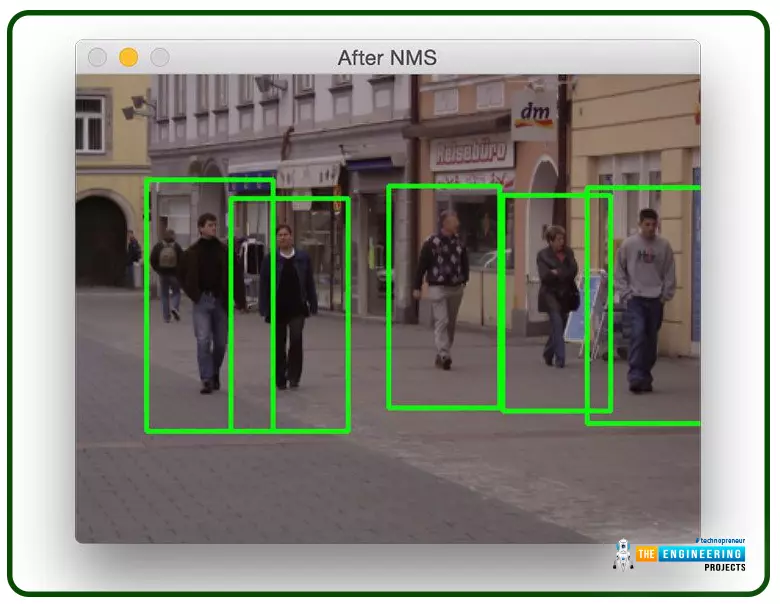
Welcome to the next tutorial on our raspberry pi four python programming. In the previous article, we built a system that recognizes when two people are in physical contact using OpenCV and a Raspberry Pi 4. We used the weights from the YOLO version 3 Object Recognition Algorithm to implement the Deep Neural Networks part. Regarding image processing, the Raspberry Pi consistently comes out on top compared to other controllers. A facial recognition program was among the earlier attempts to use Raspberry Pi for sophisticated picture processing. In today's world of cutting-edge technology, digital image processing has expanded rapidly to become an integral feature of many portable electronic gadgets.
Digital image processing is widely used for such t ...
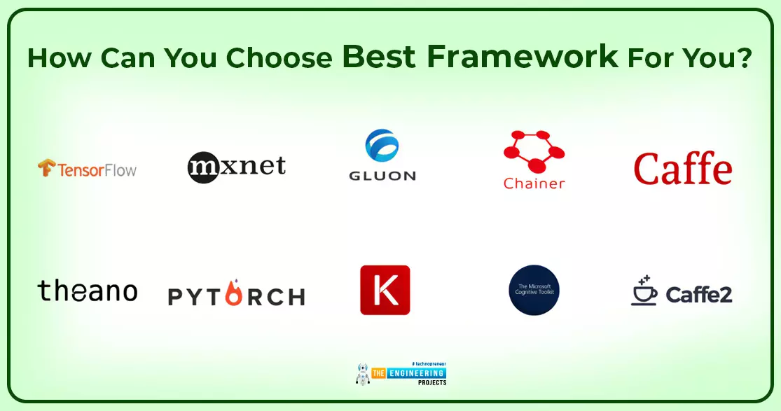
Hello peeps. Welcome to the next tutorial on deep learning. You have learned about the neural network, and it was an interesting way to compare different types of neural networks. Now, we are talking about deep learning frameworks. In the previous sessions, we introduced you to some important frameworks to let you know about the connection of different entities, but at this level, it is not enough. We are telling you in detail about all types of frameworks that are in style because of their latest features. So before we start, have a look at the list of concepts that will be covered today:
Introduction to the frameworks of deep learning.
Why do we require frameworks in deep learning?
What are some important deep learning frameworks?
What is TensorFlow and for which purpose of using Ten ...
Hi Friends! Hope you’re well today. I’ll welcome you on board. In this post, I’ll walk you through How a Hobbyist Can Work on Electronic Projects in America.From smartphones to security systems and appliances to advanced automation equipment, electronics seem to engulf every aspect of life. And with the recent advancement in technology, this trend will continue to make our lives easy and better for years on end. BUT… before you can take part in the development of innovative and advanced electronic machinery, you need to get your hands dirty with DIY electronic projects. These small and easy-to-handle projects give you confidence that you can do better and put your deliberate effort to delight the lives of people with your intellect.
If you’re just starting, we suggest you visit North Amer ...
Hi Folks! Hope you’re well today. Happy to see you around. In this post, I’ll walk you through Top Online Software Used for PCB Designing.
PCB manufacturing starts from the simple layout design. If your design is free from errors, it will not only save you tons of time and money but also accelerate the production process. You’ll find scores of PCB design software out there. Some are better than others.
So how do you keep up?
This is a difficult task, in fact. Hence we’ve compiled the list of 10 best online software for PCB designing that will help you streamline your design process and get your boards ready for manufacturing.
Keep reading.
Top Online Software used for PCB Designing
Know that if certain software is good for one project it doesn’t it will be equally h ...
Hello Learners! Welcome to the next lecture on deep learning. We have read the detailed introduction to deep learning and are moving forward with the introduction of the neural network. I am excited to tell you about the neural network because of the interesting and fantastic applications of neural networks in real life. Here are the topics of today that will be covered in this lecture:
What do we mean by the neural network?
How can we know about the structure of the neural network?
What are the basic types of neural networks?
What are some applications of these networks?
Give an example of a case where we are implementing neural networks.
Artificial intelligence has numerous features that make it special and magical in different ways, and we will be exploring many of them in dif ...
Hello students, welcome to the second tutorial on deep learning in the first one, we have learned the simplest but basic introduction of deep learning to have a solid base about what we are actually going to do with deep learning. In the present lecture, we will take this to the advanced level and will learn the introduction with the intention of learning more and more about the introduction and understanding what we want to learn and how will we implement the concepts easily. So, here is a quick glance at the concepts that will be cleared today:
What do we mean by Deep learning?
What is the structure of calculation in neural networks?
How can you examine the Neural Networks?
What are some platforms of deep learning?
Why did we choose TensorFlow?
How can you work with TensorFlow?
...
Hello friends, I hope you all are having fun. Today, we are bringing you one of the most advanced and trending courses named "Deep Learning". Today, I am sharing the first tutorial, so we will discuss the basic Introduction to Deep Learning, and in my upcoming lectures, we will explore complex concepts related to it. Deep Learning has an extensive range of applications and trends and is normally used in advanced research. So, no matter which field you belong to, you can easily understand all the details with simple reading and practicing. So without any further delay, let me show you the topics that we are going to cover today:What is deep learning?What are artificial intelligence and machine learning?Working with deep learning using neural networks.Trends in deep learning.Deep learning as ...
During the era of Covid-19, social distancing has proven to be an efficient method of reducing the spread of contagious viruses. It is recommended that people avoid close contact as much as possible because of the potential for disease transmission. Many public spaces, including workplaces, banks, bus terminals, train stations, etc., struggle with the issue of keeping a safe distance.
The previous guide covered the steps necessary to connect the PCF8591 ADC/DAC Analog Digital Converter Module to a Raspberry Pi 4. On our Terminal, we saw the results displayed as integers. We dug deeper into the topic, figuring out exactly how the ADC produces its output signals. In this article, however, we will use OpenCV and a Raspberry Pi to create a system that can detect when people are trying to avoi ...
What is a First Article Inspection?
First article inspections, originally developed for the aerospace and defense industries, are now being used as best practices in other industries. They are an effective way to ensure that the manufacturing process produces an output that meets design specifications. First article inspection helps reduce production delays and waste.
First article inspection is an integral part of the AS9145 process. It is also part of the APQP/PPAP (Advance Product Quality Planning/Production Planning and Control) approval process. The first article inspection report summarizes the design and manufacturing process of the part, including specification requirements, raw materials and associated sub-assemblies.
First article inspections are performed to ensure that t ...
Hi Guys! Hope you’re well today. Happy to see you around. In this post, I’ll walk you through What is CNC Machining? It’s Definition, Processes & Types & Components.
CNC (computer numerical control) machining has been around for a while. It is a manufacturing process where machine tools are guided and controlled by computer software. High efficiency and better control make this process ahead of the manual handling of the tools. CNC manufacturing
is done by sophisticated, complex machines that guarantee the formation of the final product with high precision and accuracy. Different CNC machines are used to treat different parts, however, each machine makes use of computer-guided software to precisely dictate and handle the machine tools. It is worth noting that the CNC systems are ...