Hey, peep! This is a connected tutorial from the previous one where we saw the detail of numeric data types. This time, we are moving forward with the other data types in Python. We are understanding all these concepts with the help of examples and practising the little but understandable codes in TensorFlow. Different types of operations are also performed on these data types so that you may have an idea of why we are differentiating all these data types and how we can categorize all of them into different groups. Keep in mind that all of these concepts are for deep learning, and we want to make sure that we will not face any problems in the complex work of deep learning; therefore, we are moving slowly and steadily in Python. So, have a look at the content you are learning in this ...
Hey fellow! Welcome to the next episode of the Python series, where we are learning the basics of Python to implement them in deep learning. In the previous lecture, our focus was on string data types. With the practical implementation of TensorFlow, many interesting points were discussed in depth. I hope you completed the home task that I assigned you during that lecture. Today, we are moving forward with the next data type, which is a sequence. You will know the different sub-groups of this data type as well in the next lecture, but today, the focus will be totally on the list because, once you understand them well, other data types of the sequence will be at your fingertips. Yet before starting, it's time to look at the content that you will learn today:
What is a sequence?
How do you ...
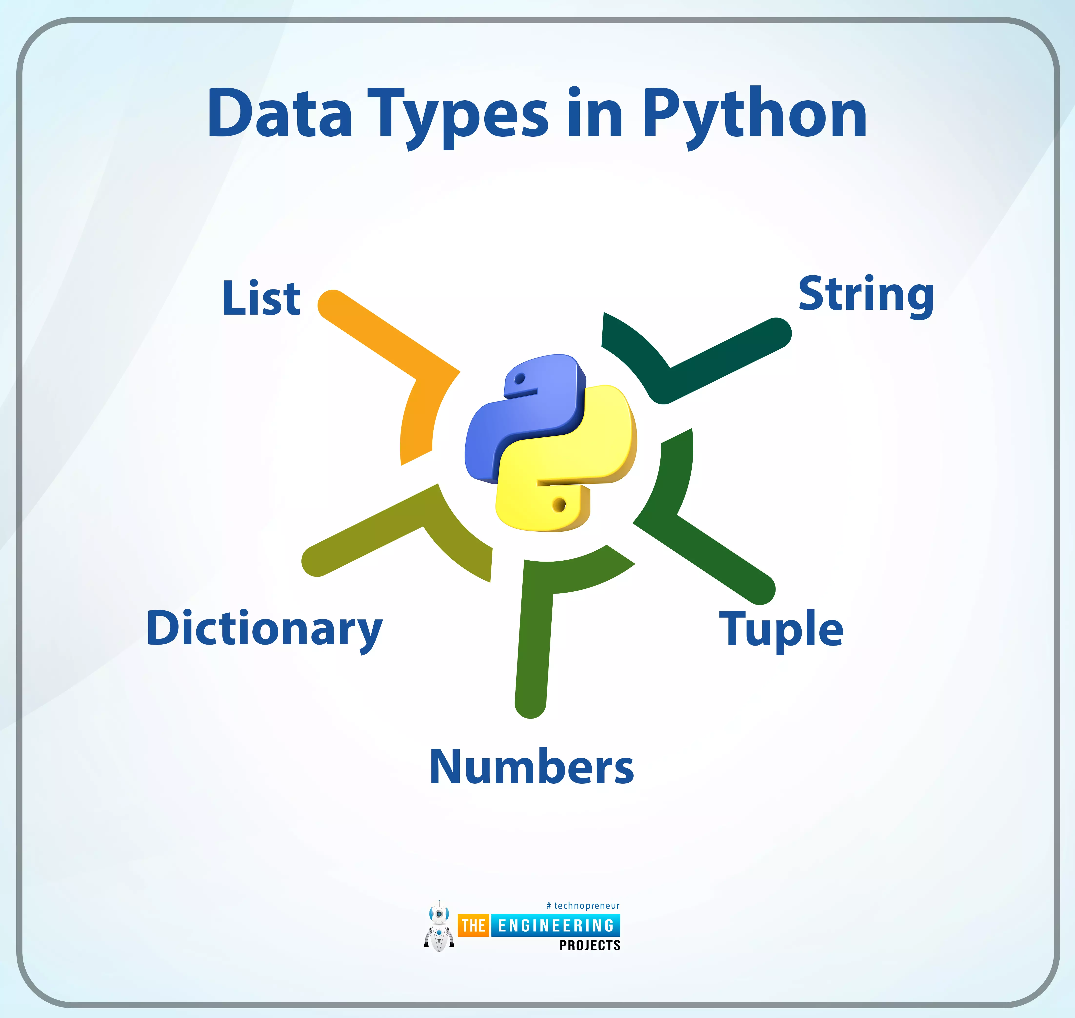
Hello learners! Welcome to the engineering projects where we are working on deep learning. In this series, we are at the part where Python is under our observation. In the last session, we saw the Python built-in functions and the practical implementation of some important pre-defined functions of Python. In the current lecture, you will learn about the fundamental concept of Python. It is not wrong to say that if you want to work in any high-level programming language, you have to understand its data types; otherwise, you will not be able to code complex or long programs using it. More details will be discussed in the next section, but before this, you should have a glance at the concepts you will learn in this tutorial.
What are the data types?
How are Python data types different from ...
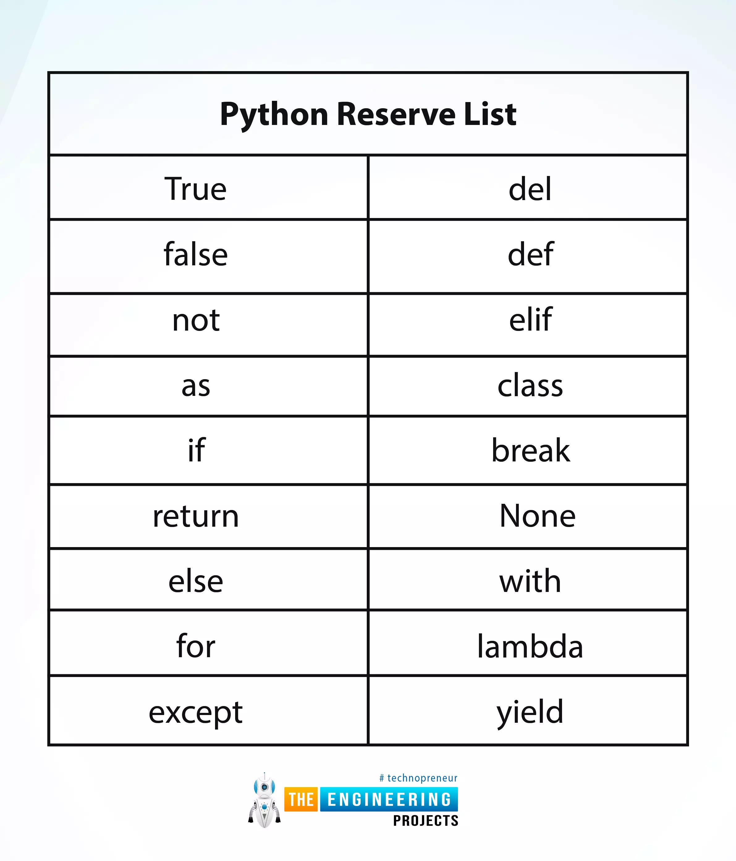
Hey peeps! Welcome to an exciting tutorial on Python in which you will learn about the Python reverse list. We are on a series of deep learning phases where Python is under our observation. In the last tutorial, we saw the variables in Python and practised many codes in the TensorFlow. Today, we are interested to practice many interesting methods in an easy way. These are the built-in functions and you do not have to be an expert in the programming to perform them in TensorFlow. All you need is to read this tutorial and have the TensorFlow working fine. Before going deep into the topic, it is important to have a look at the list of content that you will learn today:
How do you define the python reverse list?
Why we should know about the python reverse list or keywords?
How do you practi ...
Hey learners! Welcome to the new lecture on deep learning, where we are using TensorFlow to learn it with the help of Python. Previously, we worked on the syntax of Python, and now it's time to discuss the variables in detail. There are some variables that you will learn about as well as get hands-on experience within TensorFlow. These are important concepts that will help you throughout your coding career. If you are new to programming, this is a crucial concept for you, and if you know it already, you can use this tutorial to polish your concepts. We will move forward after looking at the list of content for this lecture:
What are the variables in Python?
How do you assign the value to the name of the variable in Python?
What are some rules to define the name of the variables?
How ...
Hey learners! Welcome to another deep learning tutorial, in which we are beginning the practical implementation of Python on the TensorFlow library. We installed and checked TensorFlow in detail while we were in the previous lecture, and today we are going to use it for our practice. We have checked the presence of a perfectly installed library of TensorFlow in our tutorials and seen the basic structure of this library. As a result, we will skip the details and jump right into learning Python. In this tutorial, the main focus will be on Python instead of learning the workings of TensorFlow. You have to remember one thing: all the discussion will be from the point of view of deep learning, and it is not a general tutorial in which you will learn to develop apps or have a discussion about th ...
Hey students! Welcome to the fantastic tutorial of this series, where we are talking about deep learning. Till now, the discussion has been about artificial intelligence, deep learning, and TensorFlow, but today’s lecture will change the type of discussion from the previous one. You will see that we will now talk a lot about the Python programming language and will connect all the discussions with TensorFlow. You will see the reason for both of these choices in just a bit, but before that, I want to show you the list of the concepts that will be cleared today:
What is the Python programming language when we are talking about deep learning?
Why did we select Python for deep learning when there were other options?
What is the importance of TensorFlow when we are learning deep learning by ...
In-person events provide a unique ambiance and social experience that will continue to serve a significant purpose to businesses. However, the innovation, convenience, and affordability of digital tools and resources have sparked an influx of virtual events, from team and client meetings to launch parties and webinars (and everything in between). Of course, not all virtual events aren’t created equally, as they require thorough planning and execution. Acquiring the appropriate technologies is at the heart of factors to consider.
Are you interested in hosting virtual meetings or corporate events? Check out this list of must-have technologies to make the experience more enjoyable for you and your audience.
A Dedicated Website Or Page
Planning, org ...
Small businesses rely on a specific set of technologies but optimizing the way they are used can be challenging. It is a task that requires ongoing assessment, and you will need to be able to evaluate the different options. Making these adjustments requires you to be proactive and look for potential issues before they come up. There are several ways you can optimize the tech you use.
https://unsplash.com/photos/pElSkGRA2NU
Implement Cost Saving Tech into Your Fleet
Technology can help your fleet be more efficient, especially as your business grows. One way you can improve safety is by implementing GPS systems. Many fleets use GPS to make their operations more efficient, and more applications are being discovered every day. Are you wonderin ...
The cloud software industry has begun developing new working models that have been especially needed during the pandemic. However, even though the pandemic is almost neutralized, the cloud market continues to grow. According to a new Forrester report, global software spending will continue to rise, reaching a CAGR of 10.3% from 2021 to 2023.
Therefore, in this article, we will learn more about cloud technologies and their trends.
What is SaaS?
Let's start with the definition of saas development
. This is a special software model that is provided on a subscription basis. And most often it is a cloud solution. Such a concept as software as a service is deciphered.
Top Cloud SaaS Trends
The cloud can be a very secure storage so ...