Hello friends, I hope you all are doing great. Today, we are going to start Section-III of our Raspberry Pi 4 Programming Course. In this section, we will interface different Embedded Sensors with Raspberry Pi 4. Today's our first lecture in Section-III, so I am going to interface a simple LDR sensor with RPi4.
So, let's get started:
Components Required:
The following items are required to finish this Raspberry Pi
photoresistor module guide. You don't need a breadboard to accomplish
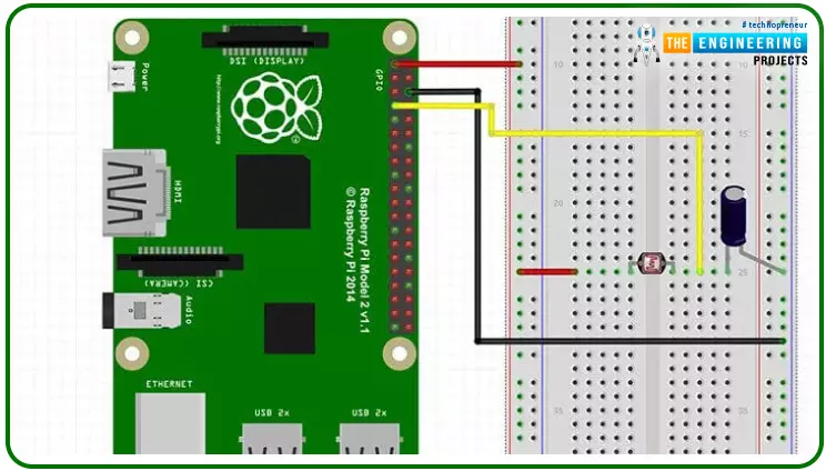
this, but having one would be helpful.Raspberry pi 4BreadboardPhotoresistor LDRJumper wires1uF Capacitor
What is a photoresist?
It is a common practice to employ photoresistors to determine the presence or absence of visible light or to quantify the amount of ...
Modern digital business needs reliable feature flag management. You probably already know that since you're here reading this article. Read it in full, then, and discover what to expect from a real-deal feature management software your company can most certainly benefit from.
What are feature flags?
Feature flags, also known as feature toggles, are a software development best practice that enables developers to safely and rapidly roll out new features in production. Feature flags provide teams with the ability to easily turn features on or off without having to deploy new code. This allows teams to quickly develop, deploy, and run experiments on their application while minimizing the risk of an unstable deployment. Feature flags can also be used to enable A/B testing and canary release ...
If you plan to run a start-up, it helps to have some basic understanding of IT management. Here are some key pointers on how best to manage your business IT systems:
You should know how your IT systems work and how they can be managed. This will help you keep them working well, which is especially important if your business depends on them for important functions like payroll or customer service. The earlier in the process that someone understands their role and responsibilities in running the company's technology, the better off they'll be when troubleshooting problems arise later on down the road.
How to Manage IT Management for Start-Ups
Make sure your hardware and software are secure.
Ensure that you have the right licenses for your ...
Hey pupils! Welcome to the new tutorial on deep learning, where we are in the section on Python learning. In the previous lecture, we were discussing the tuple data type, which is a sub-class of sequences. In the present lecture, the discussion will be about the byte sequence and byte array. The whole discussion is cleared with the help of practical implementation in TensorFlow by using simple and easy codes. If you understand the concepts of list and tuple, then this lecture will be easy for you. Yet, before going into the details of this topic, you must know the highlights of the content discussed in this lecture:
What is the byte method in Python?
How can you use byte in TensorFlow?
What are some examples of bytes?
Give examples of error handling in bytes.
How can you convert in ...
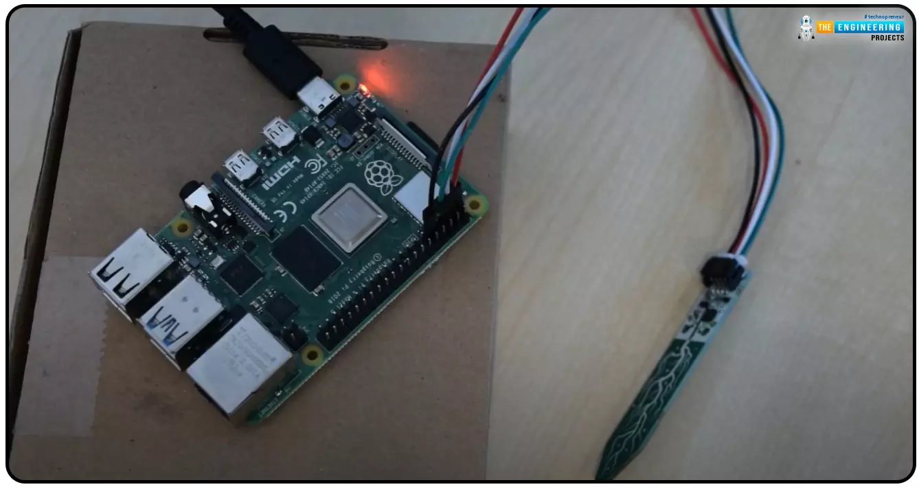
Hello everyone, I hope you all are doing great. Today, we are going to share the second chapter of Section-III in our Raspberry Pi programming course. The previous guide covered how to interface an LDR Sensor with Raspberry Pi 4. This tutorial will cover the basics of hooking up a soil humidity sensor to a Raspberry Pi 4 to get accurate readings. Next, we'll write a Python script to collect the data from the sensors and display it on a Serial monitor.
Are you aware that you can utilize a Raspberry Pi 4 to track the water absorbed by the soil around your houseplants or garden? This helpful guide will show you how to install a soil humidity sensor that will send you a text message when your plant needs watering. A Pi 4, a soil humidity sensor, and a few low-priced components are required. A ...
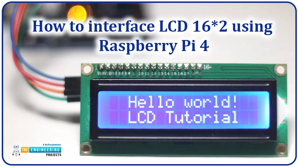
Hello friends, I hope you all are doing great. Today, I am going to share the 6th lecture in the Raspberry Pi 4 Programming series. We're glad you could join us for another lesson in our comprehensive Raspberry Pi programming guide. In today's guide, I'll show you how to interface a 16x2 LCD screen with Raspberry Pi 4.
So, let's get started:Interface LCD 16x2 with Raspberry Pi 4Today, we are going to interface a 16x2 LCD screen with Raspberry Pi 4. At first, we will print the "Hello World" text on the LCD, and in the last section, we will implement the scrolling and blinking of text on the LCD.Here's the video tutorial on LCD interfacing with Raspberry Pi 4:Components RequiredWe will need the following components for today's project:Raspberry Pi 4.M ...
We're glad you could join us for another lesson in our comprehensive Raspberry Pi programming guide. I will show you how to install and connect the RFID card chip to your Raspberry Pi through step-by-step instructions.
Modern security systems would only be complete using radio frequency (RFID) devices. To control who can enter a facility or which rooms they can access, RFID chips and card readers are employed. The RFID card's unique identification number can be read wirelessly with a wall-mounted RFID reader. A door will only unlock and allow entry if the RFID card's unique identification number matches a list of approved cards.
It's fun to tinker with this circuit, and it may be used in many other applications, from opening locks to taking a ...
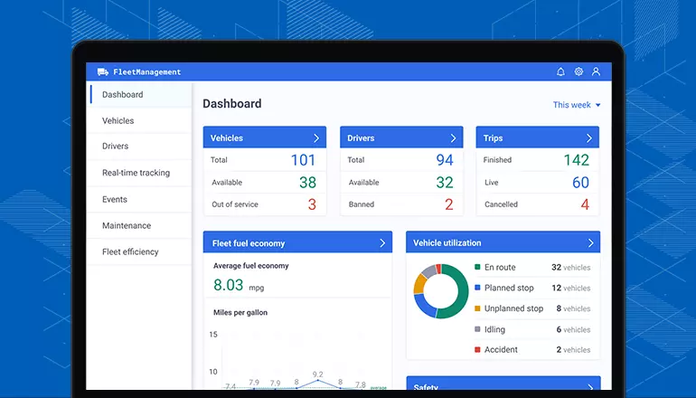
No matter your company's industry, you need fleet maintenance software. It’s something you need if your engineering firm has a fleet of vehicles. Failing to get the necessary tools is a bit like driving blind -- not the best course of action by any stretch of the imagination.
If you’re not sold on the benefits of investing in fleet maintenance software, keep reading to learn more about four reasons you need it.
1. Preventative Maintenance
Fleet maintenance software will help your engineering firm with preventative maintenance. The software will make it easy to schedule maintenance so that your fleet of cars stays in good shape.
One of the worst things you can do is delay or ignore preventative maintenance. That will ultimately cost you in ...
Hey peeps! Welcome to another tutorial on data types in Python. Our purpose in Python education is to get a grip on the basic concepts so that we may work on deep learning easily. In the previous lecture, we read a lot about lists as we are working on the subtypes of the sequence data type. In the present lecture, you are going to understand more types of sequences. If you know the list well, this lecture will be a piece of cake for you. We will start the introductions in just a bit, but before that, there must be a quick review of the topics that you are going to understand:
How do you introduce the tuples in Python?
What are some important characteristics of a tuple that must be kept in mind when we are dealing with it?
How can you practically perform the tuples in TensorFlow?
How do ...
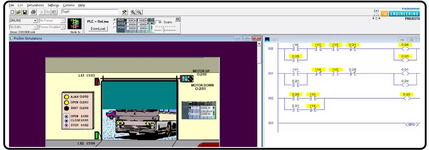
Hello my friends! I hope your doing very good. Today we are going to practice what we have learnt through the ladder logic tutorial series. We bring a new .project which is mostly exist in our daily life that is electrical door control. in garage for domestic and public garage, you should found automatic garage gate or door that is controlled by the PLC ladder logic program. So today we are going to implement the project including determining the input and output components, design the logic, programming and testing using the simulator.
Project details
Figure 1 shows the project’s components, inputs and outputs that are included in controlling the garage door. As you can see my friends, there are inputs like open, close, and stop requested by push buttons. Also, you can see sensors like ...