Hello friends, I hope you all are doing well. Today, I am going to share the 4th chapter of Section-III in our Raspberry Pi programming course. In the previous lecture, we studied the Interfacing of IR sensor with Raspberry Pi 4. In this guide, you'll learn how to interface a PIR sensor with Raspberry Pi to create a motion detector. A passive infrared (PIR) sensor is a straightforward yet effective tool for motion detection.
As a bonus, a piezo speaker will play an audio clip whenever motion is detected. GPIO pins are required for both of these accessories. This tutorial is a great starting point for those who have never worked with electronic components and circuits.
These sensors are used in traditional, old-generation security
systems. In con ...
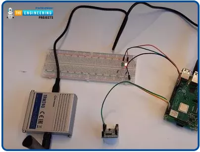
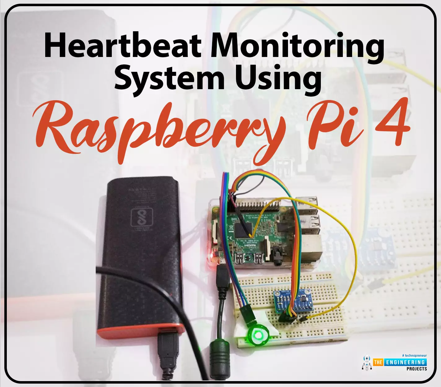
Hello friends, I hope you all are doing great. Welcome to the 11th lecture of Section-III in the Raspberry Pi 4 Programming Series. In the previous tutorial, we discussed the interfacing of the Fingerprint sensor with Raspberry Pi 4. Today, we are going to discuss another sensor named the Pulse rate sensor and will interface it with Raspberry Pi 4.The field of healthcare monitoring has long been seen as a potential use
case for IoT i.e. examining the health
instead of regular checkups and local doctors. Using sensors,
your vital signs can be monitored and transmitted in real time, allowing
a physician on the other side or even an AI to analyze the data and
provide an accurate diagnosis. That does seem somewhat futuristic.
However, we are making steady progress in that direction ...
Hi, my friends. Welcome to share a new tutorial in our ladder logic programming series. Today we will discuss counters in ladder logic programming using an expert’s view. So let’s wear the glasses of an expert in ladder logic programming and look deeply into counters, the types of counters, their variables and bits. In addition, techniques of using counters to solve a different kinds of problems that need counting. And without questions like every time, we will enjoy practicing programming and simulating all about counters. So with no further delay, let’s jump into our tutorial and nail that counters.
Counters in real life
Tell me, guys, if you can imagine an industrial project or machine that does not need to count parts, products, or processing cycles. Actually, in most cases in indust ...
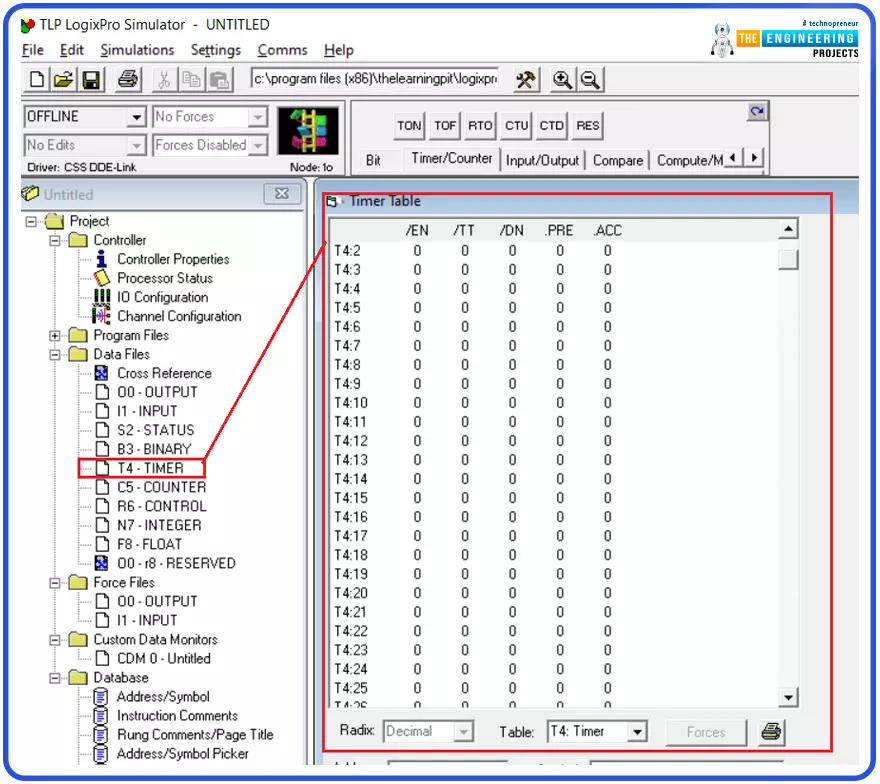
Believing in the essence of timers in ladder logic programming, we come today with a new tutorial in which we are going to show you all about timers, the types of timers, what’s inside timers’ block of parameters, variables, and bits. In addition, techniques for using timers will be explored, and for sure, we are going to practice what we learn using the simulator. So let’s get started with our tutorial.
Timers in ladder logic programming
Guys, this is not the first time we’ve talked about timers. However, this time we are going to look into timers deeply and use the glasses of practical approach. So figure 1 shows the most important types of timers in ladder logic from left to right: the on-delay, off-delay, and retentive timers. There are differences in functionality. However, they all ...
The traffic light is one of the most important applications we see everyday everywhere we go back and forth. Controlling traffic signs was managed by people which was very problematic and headache on travelers and the officers as well. But nowadays, most traffic lights are controlled by automatic control systems. The brain that handles the complicated logic behind the traffic light control system is a PLC and one programmer like you guys has written its logic. So today we have come back to enjoy programming such a critical and large project by using ladder logic programming and for sure will apply the code and the logic we write into the simulator to check its correctness.
Problem we try to solve
First of all, the scene we captured below by figure 1 shows two ways to cross a ...
Engineering projects are a crucial part of a student's engineering degree. Writing a project report is an essential part of any engineering project. The final step provides a summary of the project and its results. A good project report can help students get better grades and advance their career prospects. In this article, we will discuss the importance of engineering project writing and the steps involved in writing a successful project report.
What is Engineering Project Writing?
Engineering project writing is a form of academic writing used to document an engineering project's progress. This type of report usually includes findings, conclusions, and recommendations. It should provide a clear and concise overview of the project and its impact on society. The report should be wri ...
Thank you for being here for today's tutorial of our in-depth Raspberry Pi programming tutorial. The previous tutorial demonstrated the proper wiring of the photoresistor sensor to the GPIO pins. Finally, we learned how it might be included in a Python script for data collection and analysis needs. We also looked at the functions of each component in the circuit. However, I'll walk you through installing a Pi 4 Print Server in this guide. While installing the program is straightforward, setting it up so that a Windows network can locate the print server requires a little more effort. Rather than spending hundreds of dollars upgrading to a laser printer, you may easily upgrade your current USB printer to laser quality by installing a print server.
Because of this software, you no longer ha ...
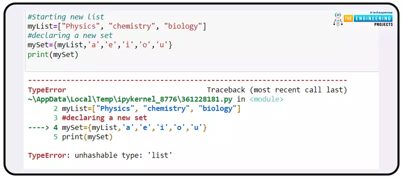
Hello students! Welcome to the new tutorial on Python. We all know that Python is one of the most popular programming languages, and there are hundreds or thousands of developers that are earning a handsome amount with the help of this easy programming language. In the previous lecture, we studied the range in the sequence, and in the present class, our concern is having the command on the sets in Python. We know you are curious about the set's details, but before this, I want to share the list of topics that will be covered in this class.
What is a set in the Python programming language?
What are some properties that distinguish the set from other data types?
What is the mutable data type, and how is it related to the set?
Introduction of the Jupyter notebook.
Can we have duplicate ...
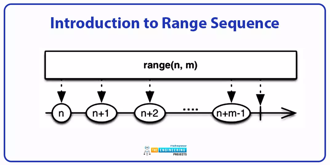
Hey peeps! Welcome to the new lecture on the sequence data type, where we are discussing the range data type. We are interested in working on deep learning, and for this, we are learning the Python programming language from scratch. If we talk about the previous episode, we saw the byte and byte array methods that were amazing for converting the different data types into bytes. The current lecture will discuss the range data type, which is slightly different from the other types of sequences, so students will learn new and interesting concepts in the lecture; however, before we get into the details of our topic, take a look at today's highlights:
What is the range function?
How can you elaborate on the syntax of the range function in detail?
What are the three types of range functions ...
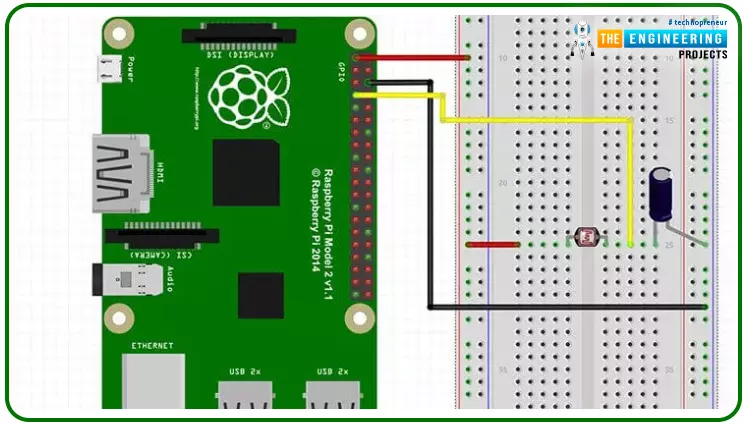
Hello friends, I hope you all are doing great. Today, we are going to start Section-III of our Raspberry Pi 4 Programming Course. In this section, we will interface different Embedded Sensors with Raspberry Pi 4. Today's our first lecture in Section-III, so I am going to interface a simple LDR sensor with RPi4.
So, let's get started:
Components Required:
The following items are required to finish this Raspberry Pi
photoresistor module guide. You don't need a breadboard to accomplish
this, but having one would be helpful.Raspberry pi 4BreadboardPhotoresistor LDRJumper wires1uF Capacitor
What is a photoresist?
It is a common practice to employ photoresistors to determine the presence or absence of visible light or to quantify the amount of ...