PCB stands for printed circuit board. You will find PCBs in pretty much all electronic devices. It is usually green/blue in color. The PCB is a circuit in a board that permanently holds all the components of a circuit. It is the main part of an electronic device. This board controls and regulates the function of the whole device. A circuit may work perfectly in a breadboard. But breadboard circuits are not suitable for use. It will only be eligible to be used in a ready-made product if implemented in a PCB. This is why PCB designing should be done with utmost care.
Where to order error-free PCBs
It takes a lot of knowledge and expertise to manufacture good-quality PCBs. PCBway is a trusted PCB manufacturer. While their head office is located in China, they ship PCBs worldwide ...
It can become challenging to make award ceremonies rewarding and fun, especially if you are in a technical business related to engineering. However, it is essential to have such celebratory moments to recognize your colleagues, coworkers, and team.
Moreover, such ceremonies are a chance to celebrate yourself and those around you, and to achieve that; the ceremony must be executed flawlessly. It must create an atmosphere of festivity and jubilation so that your team feels the spirit and recognition for their work and is, therefore, motivated to continue achieving milestones for the business.
An Engaging Host for an Engaging Awards Ceremony
Hosts bring life to the ceremony or party and must be chosen carefully for the occasion. We recommend choosing a host with some connection to your b ...
Hi readers, I hope you are all well. In this post, we can talk about the vectors briefly. Physical quantities can be defined through magnitudes but some physical quantities can be defined through both magnitudes and direction, these types of quantities defined through both magnitude and directional properties are known as vectors, and the quantities that can be explained through magnitude, not with direction are known as scalars. some vectors are force, velocity, displacement, and acceleration. Vectors can explain the direction and magnitude of the quantity but they can't provide their position. It is an essential tool of mathematics that can be used in physics for knowing the direction or magnitude. It cant be used in the 18th century but can be used in the modern era of the 19th century ...
Hi friends, I hope you are all well. Today we can talk about the dimensions of all physical quantities which include the base quantities and the derived quantities. Dimensions of physical quantities are the fundamental part that helps us understand the physical and natural properties of any physical quantity. In modern science and technology, in engineering, and in different fields of physics where physical quantities units are used, the dimensions of these units help to derive a new formula and are also used in derivations. Dimensions of physical quantities also convey the detail of the types of physical quantity.
Dimension of physical quantities also helps to check the correctness of the equation and the formula that we can derive or use to solve the problems. Dimension of the phy ...
Hi friends, I hope you are all well. In this article, we can discuss the uncertainty in the measurements which can be measured. In the era of modern science and technology or modern physics, scientists can measure complex quantities and these measurements are not precise and accurate somehow doubt is present in these measurements, these doubts are suspicious known as uncertainty in the measurements. In physics or other fields of technology and engineering measurement is essential to measure or understand the quantity of a material or an object. Because every measurement is correct there are always some doubts or doubtful digits and they are called uncertainty in the measurements.
Now in this article, we can explore the history, definition, quantifying methods, and different techniques tha ...
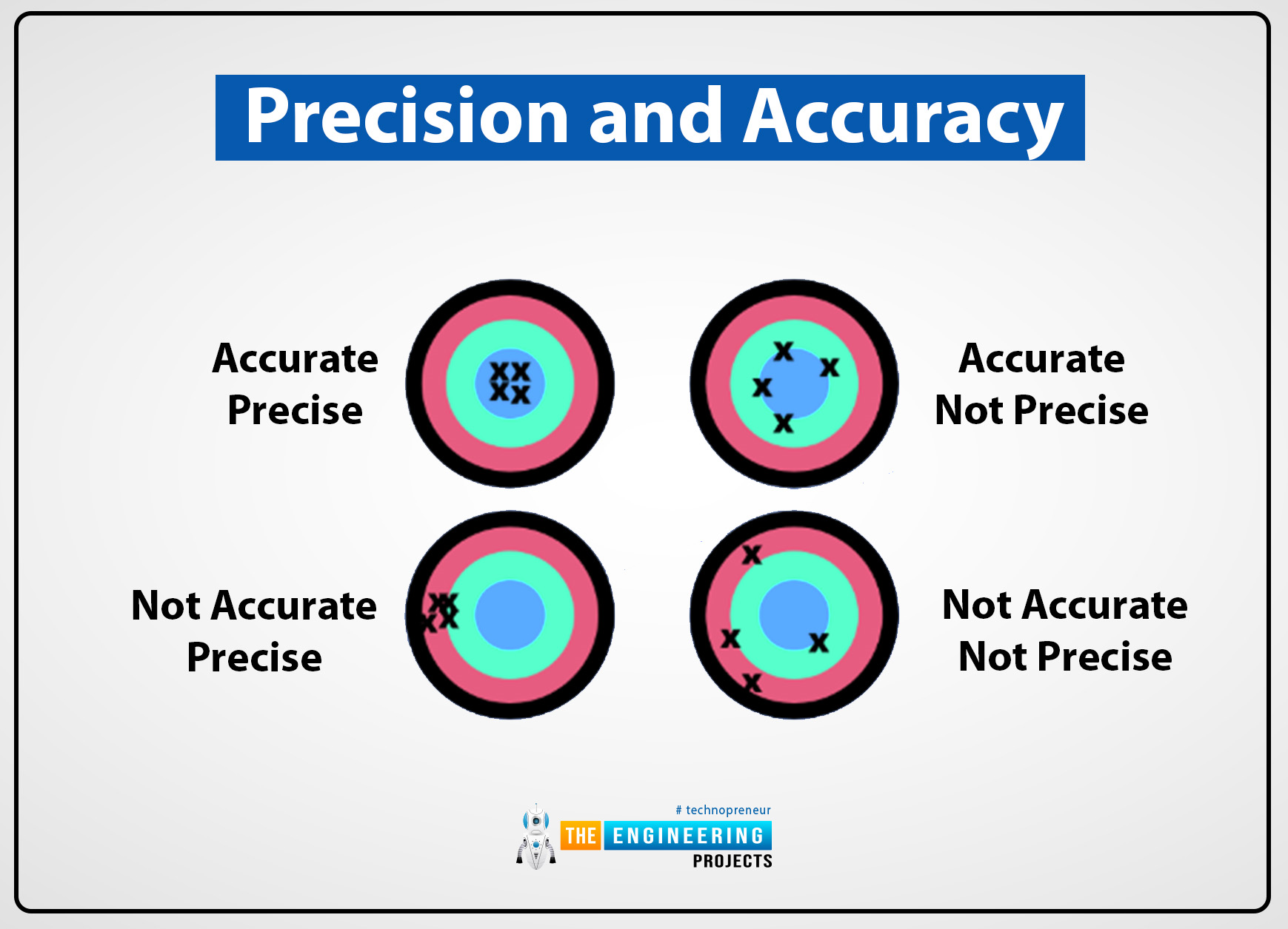
Hello friends, I hope you are all doing well. In this article, we can talk about the precision and accuracy of the measurement. Both of these are used to analyze errors in the measurements which can be calculated. In the era of science and modern technology, accuracy and precision are essential to depict the quality of the measurements. To measure the error in the measurement precision and accuracy techniques can be used because both are used for comprehensive measurement analysis.
To calculate or describe the random errors precision of measurement can be used but if we want to describe the systematic error, accuracy of measurements can be used. Now the details of precision and accuracy, their definition, differences, examples, and their application in different fields are given below:
...
It’s no secret that the tendrils of tech are tightly wrapped around the security equipment sector, and that’s good news for people and organizations with assets to protect. What you can’t afford to do is remain out of the loop on the developments that are impacting the market at the moment, so stick around and we’ll fill you in on the details that matter in 2024.
Integrating IoT with Security Systems
The combination of IoT with security systems is continuing to gain momentum this year. The idea is that interconnected devices can create smarter, more responsive security environments that are less reliant on manual monitoring. In this context it should be no surprise to find a whole host of network-enabled hardware when you explore security devices
available today.
...
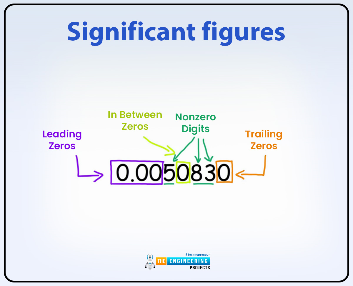
Hi everyone, I hope you are doing well. Today in this post we can discuss significant figures. Significant figures can be evolved and traced a few hundred years ago and they can be developed from time to time according to the precise calculations that can be done in mathematics and modern science and technology.The origin of significant figures can be traced to ancient times in Greece, Egypt, or many other countries where they can be used as Significant figures in calculations or mathematics. With time these significant figures can be used by astronomers, mathematicians, and scientists as well. To measure accurate and precise measurements they can use significant figures with scientific notation. In modern physics and mathematics, significant figures can be used essentially.Now we can star ...
Hi friends, I hope you all are well. In this post, we will talk about scientific notation. Scientific notation is an essential tool that scientists and engineers can use. Archemdies presented the idea of scientific notation in the 3rd century BC. His work and scientific notation ideas are based on the novel of time, known as place value.Scientific notation ideas have evolved over many centuries but are finally represented by Archimedes. In the 16th or 17th century, mathematicians continued to adopt changes in them and invent many other new notable contributions like Rene Descartes who developed algebraic notation. Scientific notation is a way in which we can express large number values in short form in the form of an exponent or a decimal form.Scientific notation not only simplifies the eq ...
Hello friends, I hope you are all good. In our previous lecture, we discussed the SI Base Units in detail and today, we are going to discuss the units derived from these base units. In 1960, the International Committee conference was held and they presented the measurement units that are used to measure all quantities worldwide.SI units are used to make accurate and precise measurements.SI units are the set of seven basic units called base units and all other units are derived from these base units and called derived units. A set of seven base units is used to measure the physical quantities but derived units are used to measure the complex quantities other than physical quantities. SI units play an essential role in modern technology and sciences.
...