Hello readers! Welcome to the easiest explanation of the current divider circuit. I hope you are doing well. In electrical and electronic circuits, the current distribution among different components and branches is the fundamental concept and it must be crystal clear in mind to understand the circuit working. One key concept that helps to understand this flow is the current divider rule, which is purely related to the parallel circuits. It is the method of determining electrical current flow into multiple paths of the parallel connection circuit.
Today, we’ll shed light on the basic introduction of the current divider and the discussion will start from scratch. You’ll see the basic concepts of the circuits, working, derivation, and applications of the current divider in the circuit. Moreover, some practical examples will be provided here for clear concepts and the learning of real-time problem solutions using current divider equations. I hope you’ll find all the required information here so let’s get started.

Current Divider Definition
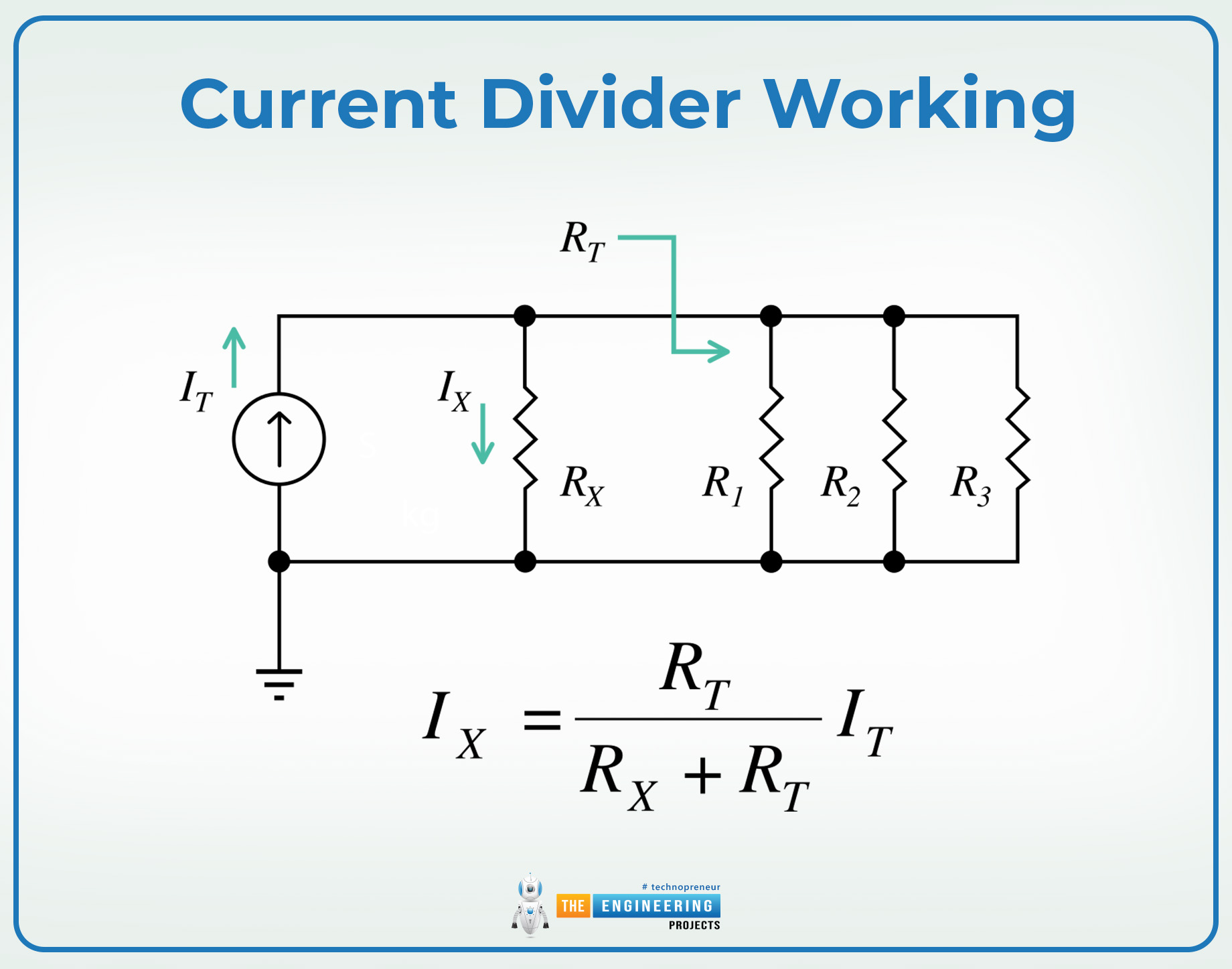
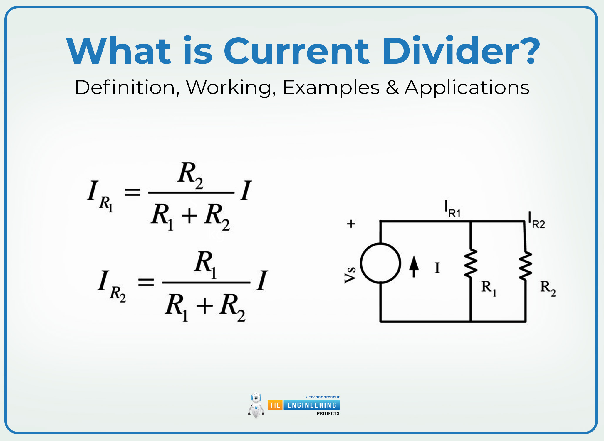
The current divider circuit refers to the circuit configuration in which the current flowing through the current source is divided into multiple parallel paths and each of them has its resistance or impedance. The amount of current flowing through each branch is determined through its resistance value. The basic principle of the current divider circuit follows Kirchoff’s current law and Ohm’s law; therefore, the derivation of the current divider also follows the mathematical representation of these two.
In simple words, the current divider enables one to determine the fraction of the total current flowing through each branch of the circuit. This becomes particularly useful in parallel circuits where the paths have different resistance values so the current is not the same across each branch.
Current Divider Basic Concepts
Before working on any circuit, one must understand the basic concept related to the topic. Here, for the current divider, it is important to understand some fundamental terms and their explanation. Even if you already know these, you have to revise them because these will be utilized in the current divider derivation.
Parallel Circuit Definition
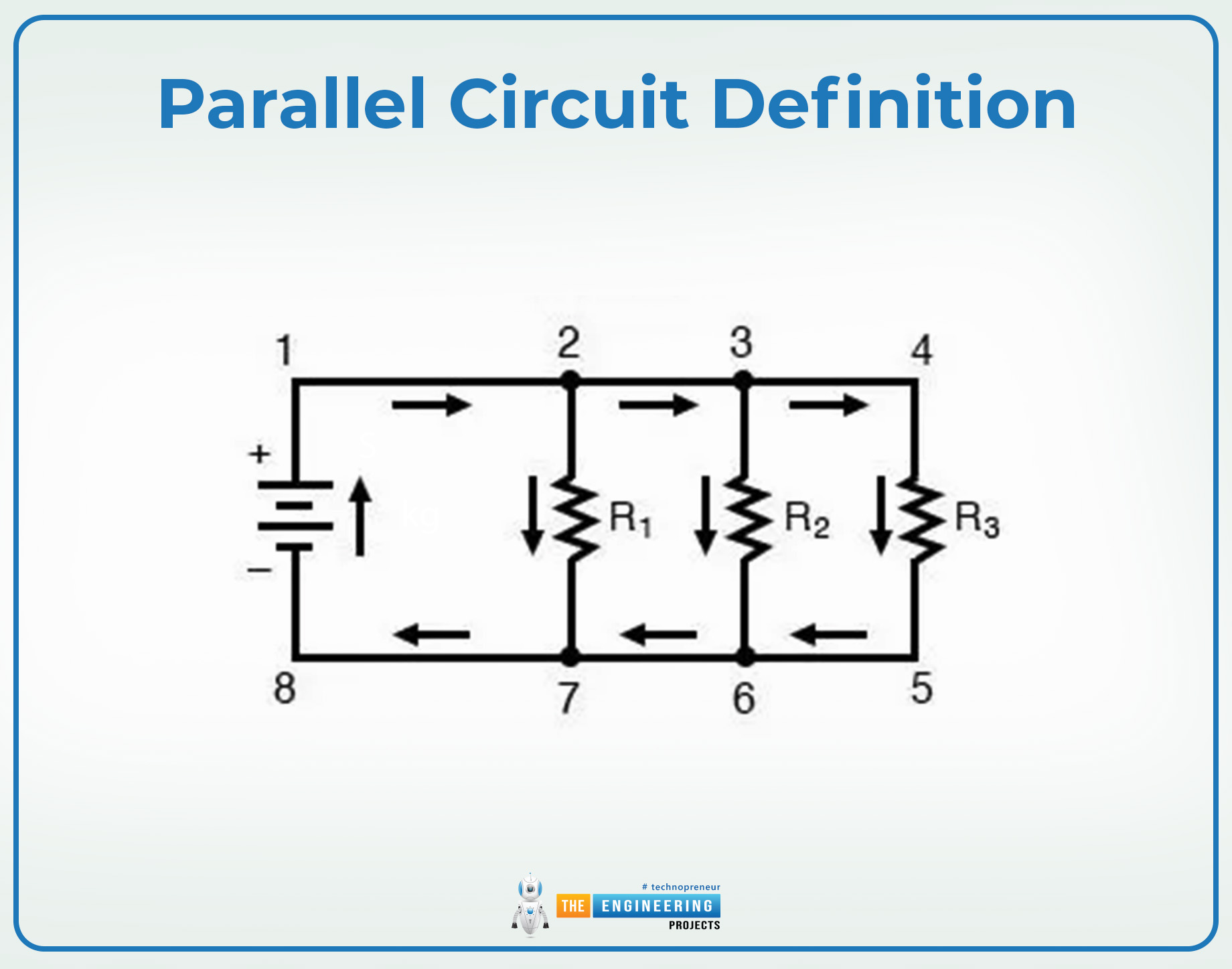
Parallel circuits are those where multiple components are connected by sharing the same two nodes. In this way, they all share the same current source, and the current flowing through each of them is divided among these components. Always remember that the voltage across each component in the parallel circuit is the same.
Electric Component Resistance
The resistance of the electrical component refers to the opposition of the current flowing through the component. It varies from component to component and plays a crucial role in the current divider rule. It is indicated by the symbol “R” and is mathematically represented as:
R=1/I
Where I is the current flowing the component.
Equivalent Resistance
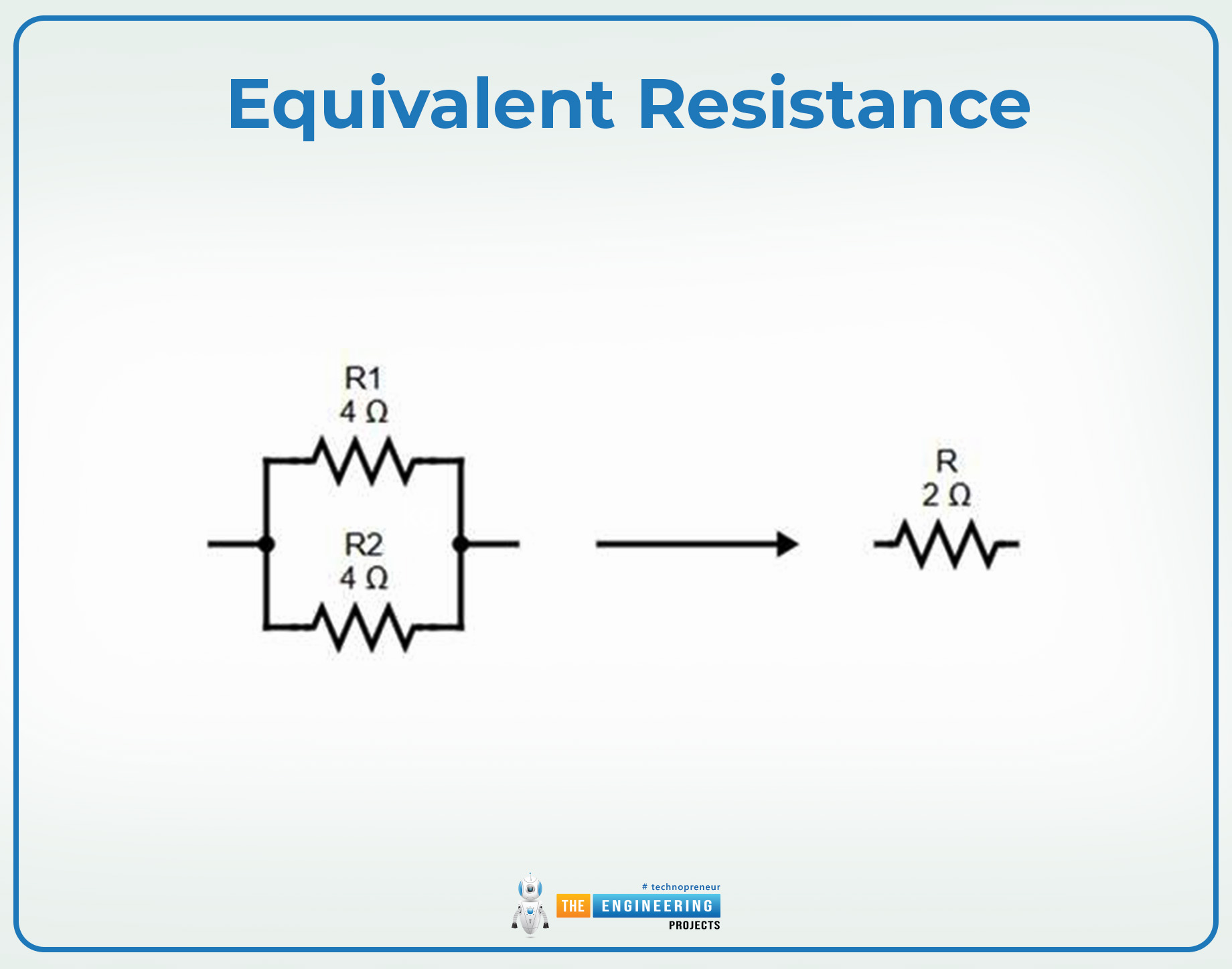
The equivalent resistance of the parallel circuit is the total resistance of the circuit or a particular combination of the components. It is represented as the Req and is the sum of the resistance of every component under consideration. If a circuit has the N number of components, then the equivalent resistance of the circuit is represented as:
Req=I/R1+1/R2+1/R3+......+1/Rn
Ohm’s Law
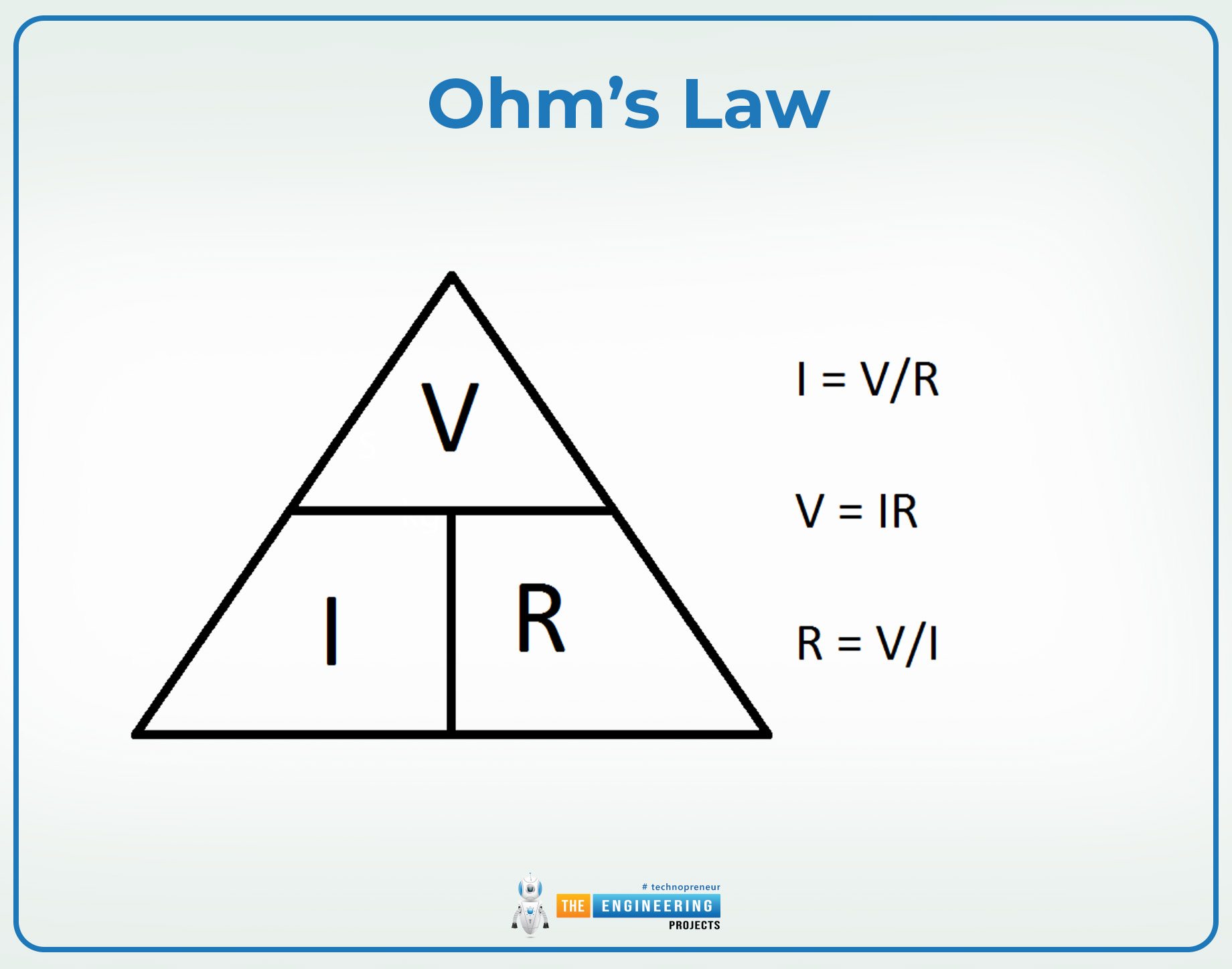
Ohm’s law is the fundamental law in electrical engineering, and it involves the representation of the voltage, current, and resistance of the circuit. This law states that:
“The voltage across the conductor is directly proportional to the product of resistance and current of a component, provided the temperature and other physical conditions remain the same.”
The mathematical expression for the above statement is given below:
V=IR …………….. (1)
Where,
V= Voltage of the conductor
I= Current flowing through the conductor
R= Resistance offered by the conductor
Kirchoff’s Current Law (KCL)
Kirchoff’s current law is another fundamental concept in the electrical circuit that states that:
"The sum of all the currents entering the particular node is equal to the sum of all the currents leaving the node."
In simple words, the algebraic sum of all the current entering the node and flowing out of it is always zero. The mathematical representation of this rule is given here:
∑Iin = ∑Iout ……….(2)
Here,
∑Iin= Sum of all the current entering the node
∑Iout= Sum of all the currents leaving the node
In other words, the total current passing through the circuit is equal to the sum of all the currents passing through each component of the circuit.
IT=I1+I2+I3+.......+In …..(3)
Current Divider Working
The core principle of the current divider rule is based on Ohm's law and Kirchoff’s current law. These two, when combined, can be applied to solve the intricate circuit with multiple nodes and paths. Let’s rearrange Ohm’s law and derive the current divider equations. In the parallel circuits, the voltage across each component is the same. Hence, use equation 1:
V=InRn
Rearranging the above equation gives us the following:
In=V/Rn ……….. (4)
Let's say we have a parallel circuit with the two resistors R1 and R2. Ohm’s equations in this case are:
I1=V/R1 for R1 ……….. (5)
I2=V/R2 for R2 ……….. (6)
Applying Kirchoff’s current law here, utilizing equation 4:
IT=I1+I2
IT=V/R1+V/R2
IT=V(1/R1+1/R2)
IT=V(R2+R1/R1R2) …………. (7)
For the potential difference in a circuit, the above equation becomes:
V=IT x (R1R2/R2+R1) ……….. (8)
Substituting the values of V in Equation 5
I1=IT x (R1R2/R2+R1) /R1 ………… (9)
Similarly, utilizing equation 6 for I2
I2=IT x (R1R2/R2+R1)/R2 ………. (10)
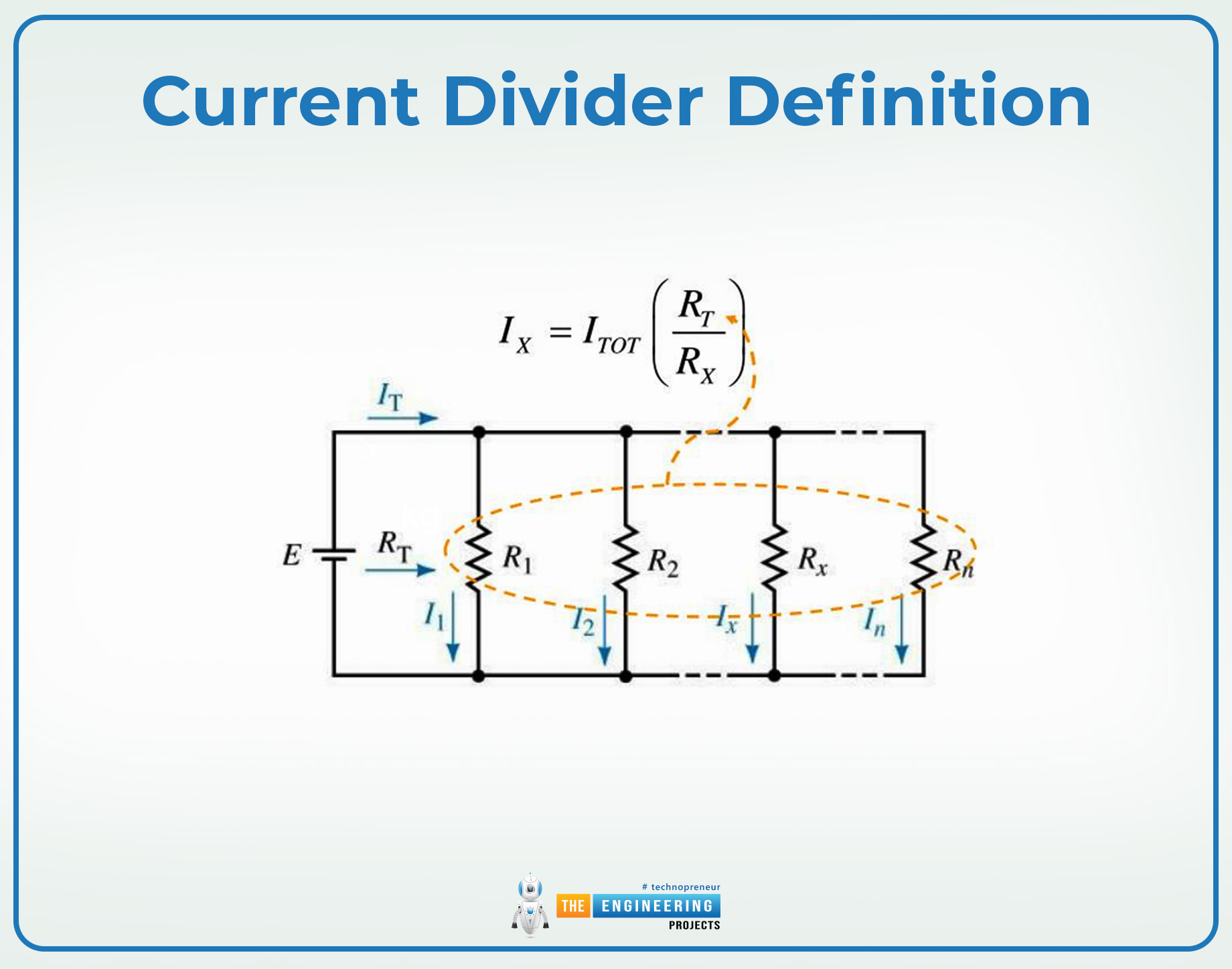
Generally, to find the current in the single node, the equation can be rearranged as:
In=Itotal(Rtotal/Rn) ……….. (11)
Where n denotes any path number.
As a result, the current divider equations can be applied to find the total current of the circuit or to calculate the individual current from any branch.
Current Divider Examples
Let's explore some practical applications of current divider equations through a series of simple circuit examples. For this, we’ll be employing the above-derived equations.
Current Divider Example 1
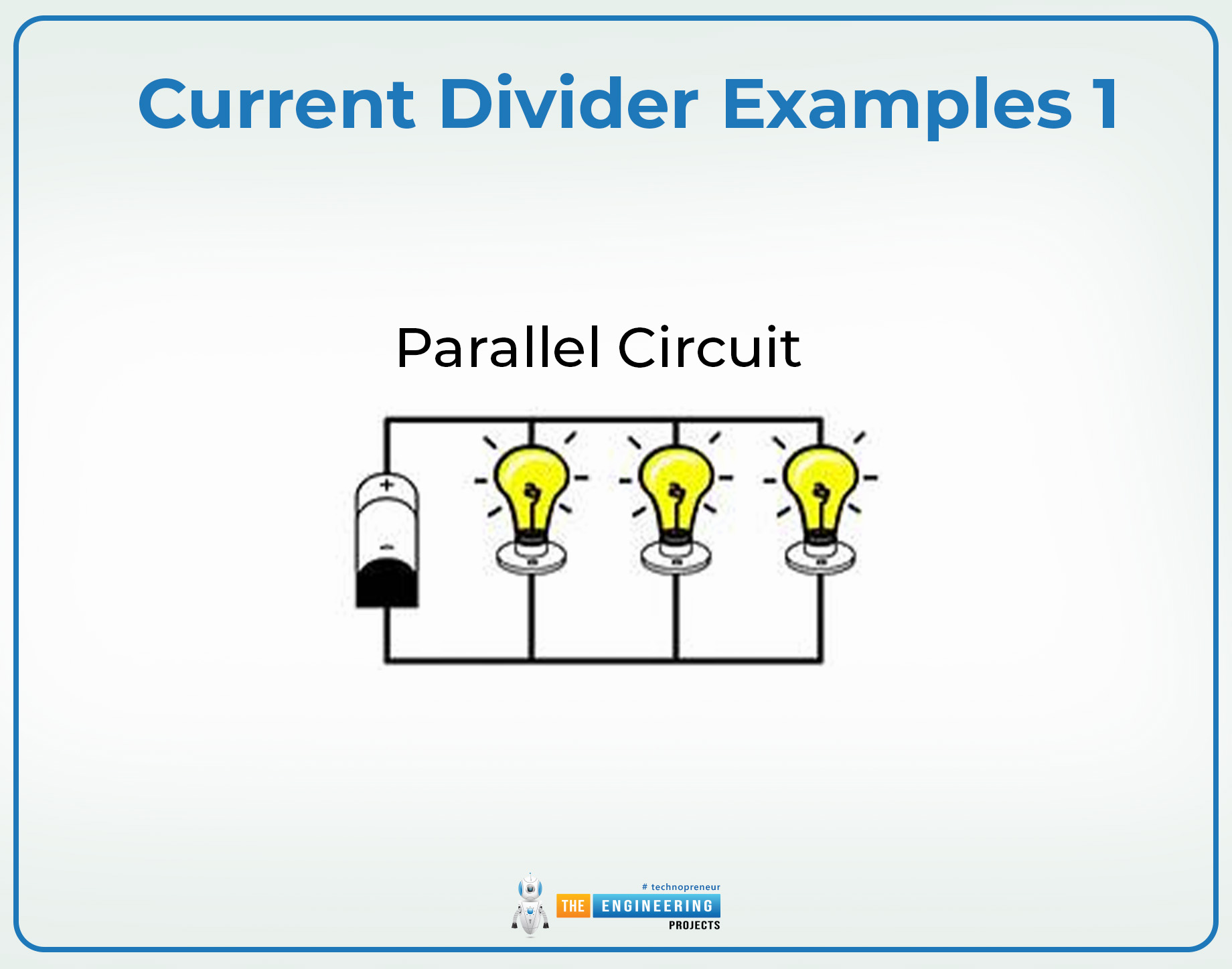
The following is a parallel circuit with three branches; each branch contains a bulb that acts as a resistor. The resistance in these bulbs is denoted as R1, R2, and R3. The resistance values are 10 ohm, 12 ohm, and 13 ohm, respectively and the voltage of the source is 12V. Apply the current divider rule and find the current flowing through each branch.
Given data:
R1=10Ω
R2=12 Ω
R3=13 Ω
V=12 V
To find the equivalent resistance, apply the formula:
1/Req=I/R1+1/R2+1/R3
1/Req=I/20+1/12+1/13
1/Req=0.1+0.0833+0.0769=0.2602
Taking the reciprocal
Req=1/0.2602
Req≈3.844Ω
To find the total current of the circuit, apply Ohm’s law
IT=V/RT
IT=12/3.844
IT=3.14A
Now, utilizing equation 11 for individual currents
In=Ieq(RTl/Rn)
For I1
I1=IT(Req/R1)
I1=3.14(3.844/10)
I1≈1.2A
For I2
I2=IT(Req/R2)
I2=3.14(3.844/12)
I2≈1.0A
For I3
I3=IT(Req/R3)
I3=3.14(3.844/13)
I3≈0.923A
To verify our results, let's sum up all the currents using equation 3 to see if these are equal to the total current or not.
IT=I1+I2+I3
IT=1.2+1.0+0.923
IT≈3.1.4
The results are approximately identical.
Current Divider Example 2
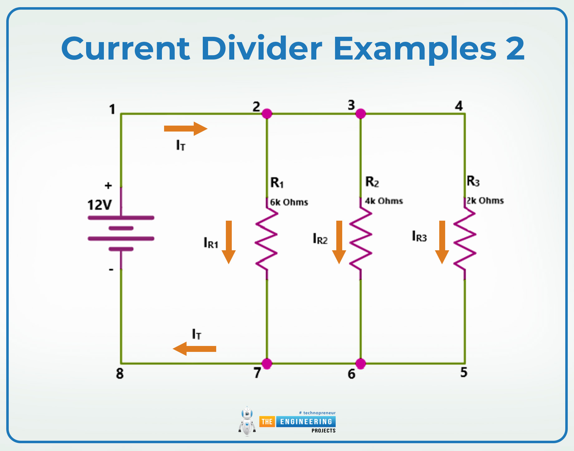
The given circuit represents a parallel configuration with three resistive branches powered by a 12V source. The resistors, R = 6 k ohm, R=4k ohms, and R3 = 2 k ohm, share the same voltage. Find the tidal current flowing through the circuit and the current passing through each node separately using the current divider rule.
Given data:
R1=6kΩ
R2=4k Ω
R3=2k Ω
V=12 V
Let’s figure out the equivalent resistance of the circuit using the equation
1/Req=I/R1+1/R2+1/R3
1/Req=I/6000+1/4000+1/2000
1/Req=0.000167+0.00025+0.0005=0.000917
Taking the inverse of the above values
Req=1/0.000917
Req≈1091Ω
To find the total current of the circuit, apply Ohm’s law
IT=V/RT
IT=12/1091
IT≈11.00mA
Now, let’s use the equation 11
In=Ieq(RTl/Rn)
For I1
I1=IT(Req/6000)
I1=11(1.91/6000)
I1≈2mA
For I2
I2=IT(Req/R2)
I2=11(1.91/4000)
I2≈3mA
For I3
I3=IT(Req/R3)
I3=11(1.91/3000)
I3≈5.50mA
Let’s sum up all the currents to verify the results
IT=I1+I2+I3
IT=2mA+3mA+5.50mA
IT≈11mA
Current Divider Applications
The current divider rule has a fundamental role in the current and parallel circuit analysis in electrical and electronic circuits. The following section provides information about the basic electrical applications and the use of current divider equations to find the missing values. This not only provides the right information about the circuit but helps to maintain the component’s lives.
Current Divider for Transistor Circuit Baising
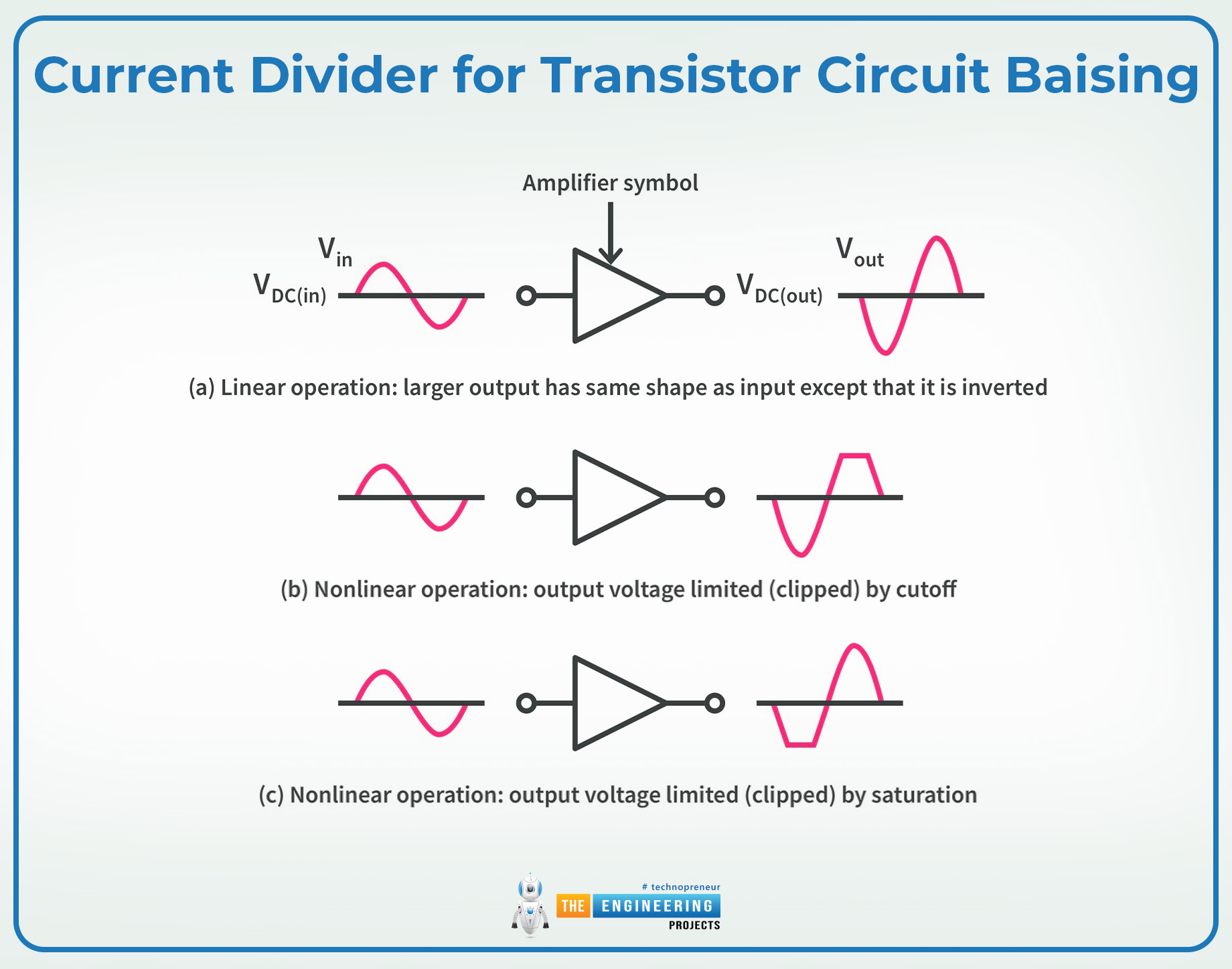
The transistor always works on a specific range of currents and voltages; therefore, maintaining the right current values is crucial. The current divider is applied to provide the important biasing current to the base of the gate terminal of a transistor for optimal performance. This is especially critical when an application has hundreds of thousands of transistors of the same kind working together.
Current Divider in Power Distribution Systems
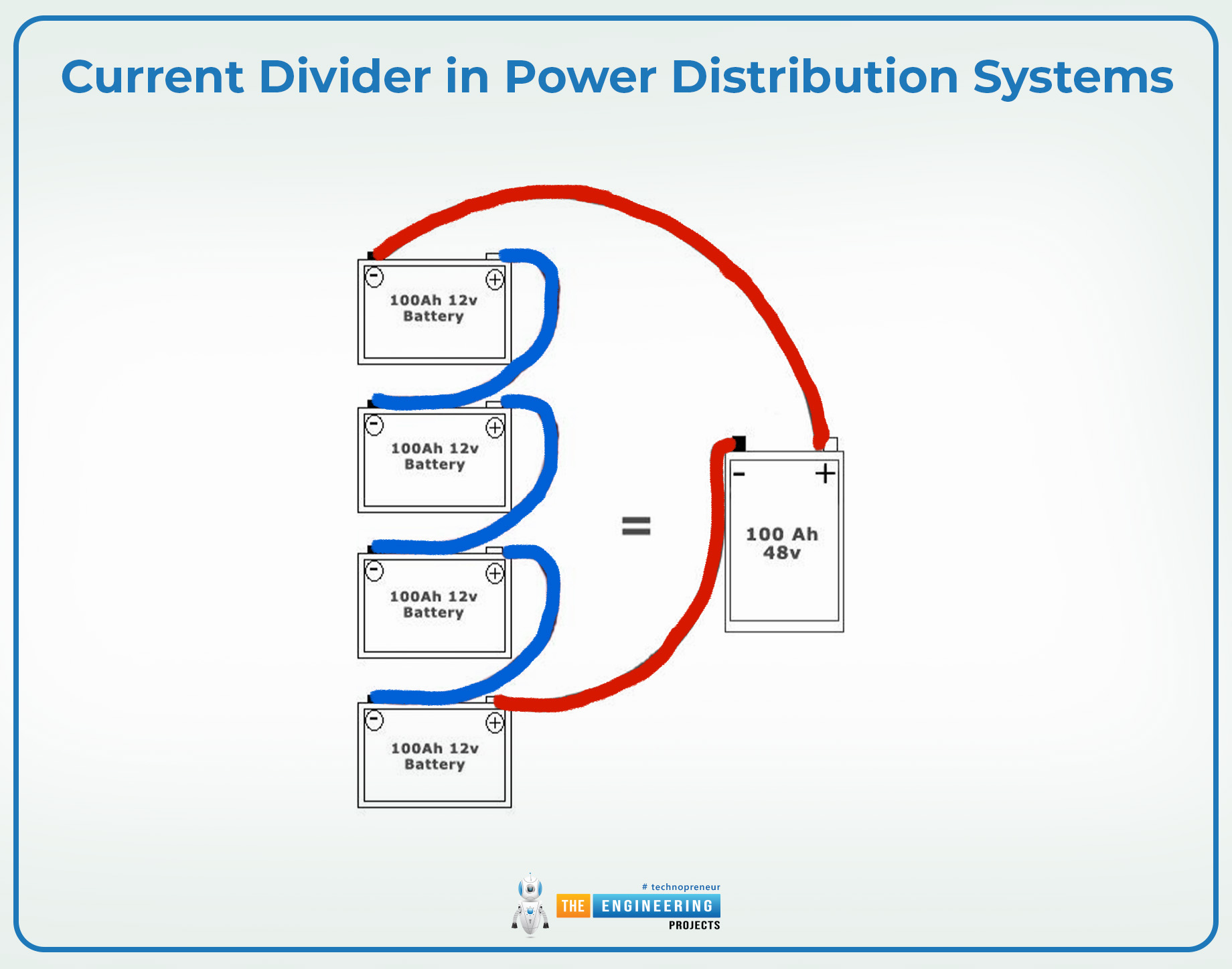
In power distribution systems, optimal load sharing is important to maintain the system’s performance and the component’s integrity. This is done by carefully applying the right load to each component and the current divider rule and equations are useful to calculate the right load on multiple branches.
For instance, in the parallel battery connection, the right load must be applied to each battery according to its capacity. The current divider rule ensures that each battery shares the right load enhancing its efficiency and longevity.
Current Divider for Component Safety
The current dividers help in the circuit to regulate the working for a specific limit. The resistance values of the component are perfectly set so no component gets more current than its tolerance values. The appropriate resistance values ensure the safety and performance of the particular component.
Current Dividers in Telecommunication
In telecommunication, a particular amount of single transmission is crucial, and one way to manage the signal distribution is to employ the current divider circuit. It helps in the right division of the signal among different pathways and to optimize the network’s performance.
In addition to this, the current dividers are applied for the right impedance matching so all the signals can be distributed to the right component.
Current Divider in Voltage to Current Conversion
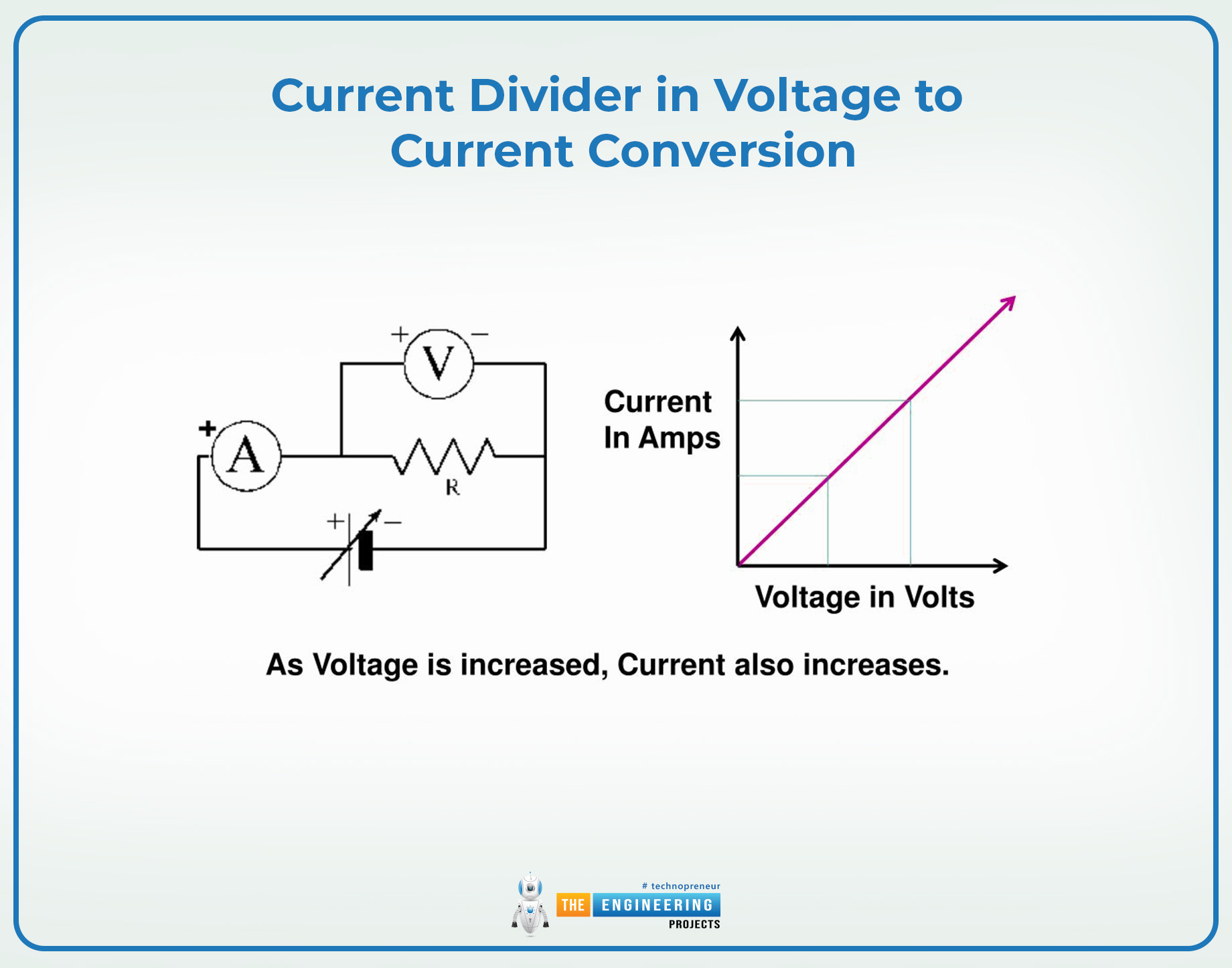
In some circuits, only a fraction of the current is converted into voltage and this calculation must be accurate. This is done using the current divider calculations by selecting the right resistance values. As a result, the exact values of the current output can be gained that are directly proportional to the input voltage values.
Current Dividers in Common Circuits
The current divider is applied to multiple types of circuits ranging from simple to complex ones. For instance, in the light connection circuits, the current dividers are used to control the bulb brightness through the current limitations. It ensures that every bulb is getting the right amount of current and it can vary according to the total current applied to the whole circuit.
Similarly, these circuits are applied to the audio system to control the volume of the speaker or other output devices.
The applications of the current divider do not end here, but now you may have an idea about its working, applications, examples, and importance through this article. It is a fundamental concept in the circuit analysis that is employed to solve the intricate circuits. I hope this was a useful study for you. If you want to lean more, you can ask in the comment section.


