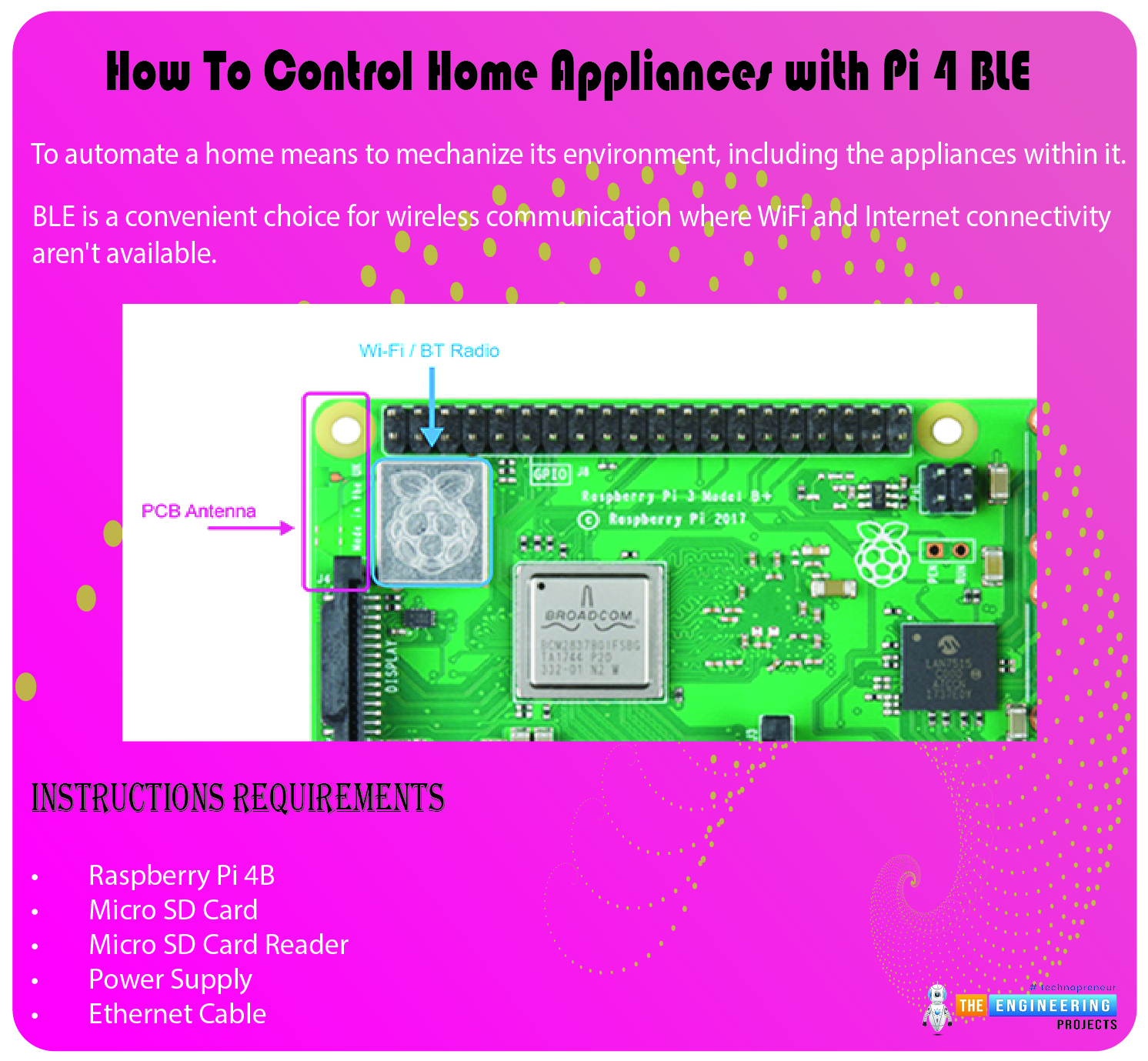
Welcome to the next tutorial of our raspberry pi 4 tutorial. In the previous tutorial, we learnt how to interface a gas sensor with a pi 4. However, in this tutorial will cover how to automate your home with a Raspberry Pi and Bluetooth Low Energy. To automate a home means to mechanize its environment, including the appliances within it. To that end, we've designed an intelligent lamp whose functionality can be adjusted from afar via a companion mobile app.
Using your smartphone, you'll be able to manage a variety of household gadgets. The following code demonstrates using a mobile device as a remote controller for a Raspberry Pi's GPIO pins. (Or another BleuIO Dongle).
Instructions Requirements
The recently introduced Raspberry Pi 4 will serve as our testbed, but the lessons learned here should apply to any Pi board. You'll need these things if you want to follow along:
Raspberry Pi 4B
Micro SD Card
Micro SD Card Reader
Power Supply
Ethernet Cable
As a result of its low price and excellent integration, the Raspberry Pi has quickly become a popular platform. This board has Wi-Fi, Ethernet, and Bluetooth Low Energy (BLE) connectivity.
Bluetooth functionality on the Raspberry Pi is variant-specific.
The Raspberry Pi has a built-in Wi-Fi and Bluetooth Low Energy chipset so that you can connect wirelessly. Depending on the motherboard, different chipsets may be supported. Previously, Raspberry Pi 3A utilized Broadcom's BCM43438 chipset, but now it uses Cypress's CYW43455 chipset, which adds compatibility for 802.11ac and dual-band Wi-Fi. (2.4GHz and 5GHz).
For Bluetooth support, all Raspberry Pi models use the free and open-source BlueZ stack. Although this stack has been around for quite some time, it only recently began supporting Bluetooth Low Energy (BLE), so it has some limits and occasional errors. BlueZ should be rigorously tested in a production environment before being deployed.
Raspberry Pi's Bluetooth 5.0 compatibility is minimal and only includes minimum functionalities. Most notably absent is Long Range support, which means you can't take advantage of the Coded PHY for a particularly outstanding range. Combination Wi-Fi and Bluetooth chipsets rarely include this function.
How Well Does the Raspberry Pi Perform With Bluetooth Low Energy?
It's important to talk about performance before we dive into actually using the Raspberry Pi. After all, with it, even one of our guides would be complete. The Raspberry Pi's performance and low price have made it a popular gateway system in recent years. We've incorporated it into a couple of other projects ourselves.
The good news is that the Pi uses Broadcom and, more recently, Cypress chipsets, which provide decent RF performance and features. Support for some devices' higher-frequency 5 GHz WI-Fi channel helps keep the BLE-optimized 2.4GHz spectrum free of interference. Since it is a single-chip solution, interference can be minimized by using the Coexistence feature. The most severe issue is the Raspberry Pi's tiny antenna. The GPIO connector pins enclose this antenna to some extent. Both can affect performance, but the RPI base doesn't reveal specifics on antenna radiation.
Due to several factors, the antenna of a Raspberry Pi cannot be altered.
Soldering an antenna is required because there is no actual connection.
The presence of an external antenna is not shown in the Raspberry Pi certification. The FCC and other credentials are void if the board is altered in any way.
The Raspberry Pi devices' Bluetooth LE range is adequate but not great; it cannot compete with a more advanced system with an additional antenna. To extend the range of your device control beyond a single room, you'll need to either add another radio or devise another solution.
In light of the preceding, it could be an effective method for managing electronics inside the house. Let's get started with Raspberry Pi automation right away.
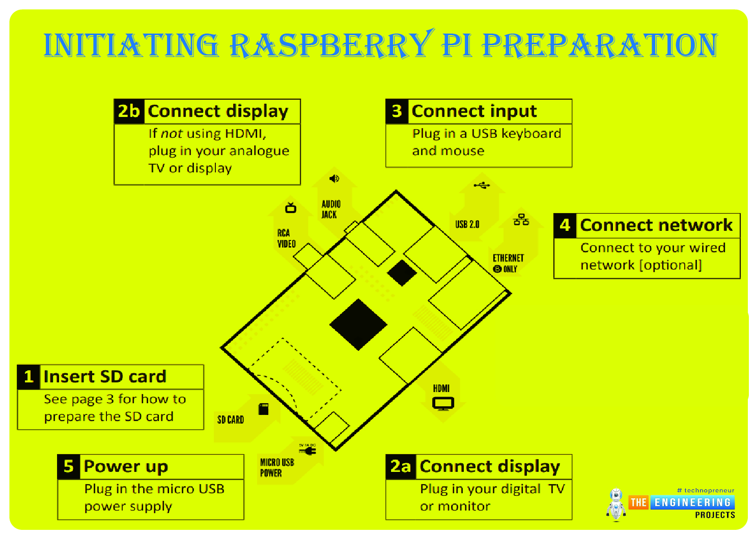
Initiating Raspberry Pi Preparation
If you're starting with a working Raspberry Pi, you may jump to the section titled "Installing the BlueZ Bluetooth Stack on the Raspberry Pi."
The Raspberry Pi utilizes a unique flavor of Linux. We'll be installing Raspbian. The SD Card image file must be downloaded before it can be written to the card.
Raspbian Buster, published in July 2019, is the most recent version of this guide's publication.
As a result of its superior speed, the Torrent protocol comes highly recommended. After downloading, unpack the archive into a new directory.
Making an SD Card
Depending on your system, you can create the Raspbian SD card. The quickest method to achieve this in Windows is as follows:
Win32DiskImager-1.0.0-binary.zip is the recommended version of Win32DiskImager; download it here.
Connect your microSD card to your computer with an external MicroSD Card reader.
Run Win32DiskImager.exe, navigate to the Raspbian is img file within the zip archive, and then pick the appropriate drive corresponding to the micro SD card.
The next step is to select Write to start composing. The process of writing will now begin. The time required for this operation is highly variable and depends on the speed of the memory card and the reader.
As there are a few moving parts, we suggest following the installation procedures found in Installing OS images on Linux.
How to Hook Up to a Raspberry Pi
Serial Linking
Several methods for interacting with the Raspberry Pi, such as a mouse and keyboard. However, we typically utilize Serial Port or SSH due to the speed of the command line.
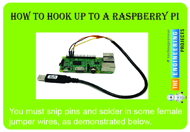
A universal serial bus to UART converter cable is required to access the Raspberry Pi's command prompt. Mouser, Digikey, and many other retailers sell all of these components. Some suggestions are provided below.
Mouser - TTL-232R-3V3-WE
Adafruit - FTDI Serial TTL-232 USB Cable
SparkFun - FTDI Cable 5V VCC-3.3V I/O
3.3V I/O is the norm for Raspberry Pi cables. These cables require severing the ends and correctly connecting them. We employ the FTDI TTL-232R-3V3-WE cable here.

The TTL-232R-3V3-WE only has three pins, which are all depicted in the above diagram. The cables themselves are colored black, yellow, and orange. A 6-pin connector is pre-soldered to some wires, but you cannot use it because the pinout is incorrect. Instead, you must snip them and solder in some female jumper wires, as demonstrated below.
The Raspberry Pi's serial console output is turned off by default. As a means of making this possible:
Remember to put the Memory card into your computer. Two partitions should be displayed, one of which is the boot partition.
In the boot partition's cmdlineargs.txt file, append the following lines:

enable_uart=1
This way, you won't have to worry about using SSH, getting disconnected, etc., before using serial. Instead, if you're interested in utilizing SSH, read on for instructions.
Using SSH for a Connection
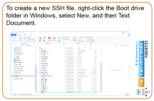
Make a folder in the boot section and name it SSH. The file should be called "SSH"; no quotes or extensions are necessary. To create a new SSH file, right-click the Boot drive folder in Windows, select New, and then Text Document. Respond with "Yes" when prompted by Windows to allow the extension.
Warning: syncing may fail if you don't eject (Windows) or unmount (Linux/Mac) the SD card now.
The Raspberry Pi can be set up by connecting an Ethernet cable, a 5V power supply, and an SD card. All of the board's LEDs should be functioning.
Connecting via Serial will bring up the Raspberry Pi interface, where you can log in with the details provided up top. Check the pin connections and swap the TX and RX wires if necessary if no prompt appears.
You'll have to know the Raspberry Pi's IP address in order to connect to it via SSH. It can take time to locate. Among the methods we employ is a rapid network scan using NMAP to identify any devices that may be present. Raspberry Pi will announce its identity and IP address. The MAC address assignments are also viewable via the router interface.
Control RPI using Putty.
To connect to the device via Serial or SSH, you'll need a program like PuTTY. Follow this link to download PuTTY:
For the 64-bit version, click the link mentioned above. You can skip setting up PuTTY. Turn on PuTTY, and then either
To connect to the Raspberry Pi, you must first enter its IP address into the SSH client.
(Serial) Use 115200 baud and the COM port your USB - UART converter is connected to, then click Open.
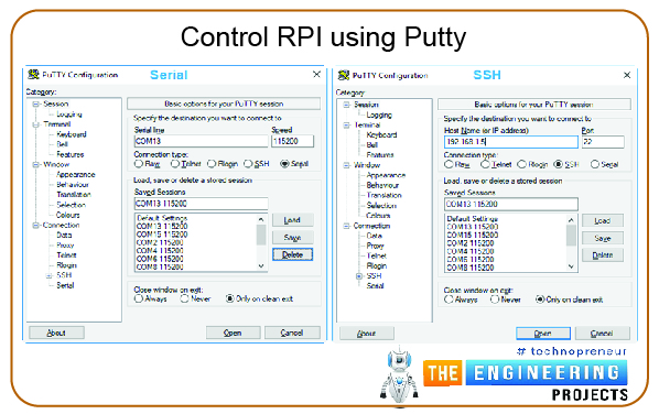
Use the default credentials of "pi" and "raspberry" to log in.
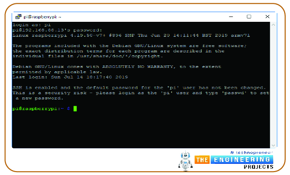
A few maintenance tasks
Certain things must be taken care of before we begin tinkering with BLE on the Pi 4. Let's make more room for our files by increasing the size of the file system with the help of the Raspbian configuration utility.

sudo raspi-config
In the option that appears, choose Expand Filesystem under the advanced tab. To save your changes, please click back and then Complete. The Raspberry Pi must then be rebooted to ensure the settings have taken effect.

sudo reboot
Using SSH? You'll need to reconnect. Right-click the PuTTY window and choose "Restart Session" for a quick restart.
Completing the Raspberry Pi's Bluetooth stack installation with BlueZ
It's time to install BlueZ on our Raspberry Pi now that it's all setup. Open-source framework Bluetooth stack BlueZ was previously mentioned. The Raspberry Pi Foundation has already taken care of the low-level configuration of the Wi-Fi / Wirelessly chipset. You need to set things up as though it were a bespoke hardware platform, like others with which we've previously worked.
Firmware is stored in read-only memory (ROM) on Wi-Fi and Bluetooth chipsets and their hybrid versions. The ROM firmware requires updates and bug patches. The RPI foundation already installed these fixes and upgrades when it installed the Bluetooth and Wi-Fi drivers. In some circumstances, it may be necessary to revise it. Therefore we bring it up. Fortunately, we can skip taking action, as the predefined values are adequate.
BlueZ will need to be installed manually, even though Bluetooth packages are already available for download in Raspbian. You should be able to update to the most recent version, install updates, and possibly alter the build to add desired functionality. The BlueZ version and its prerequisites must be installed for this to work. To get your hands on BlueZ's underlying code, follow the links below. Please take note that the current stable version of BlueZ is 5.50.

cd ~
wget http://www.kernel.org/pub/linux/bluetooth/bluez-5.50.tar.xz
tar xvf bluez-5.50.tar.xz
The preceding commands download and extract the BlueZ source code; in this example, version 5.50 of BlueZ will be used. The Raspberry Pi's processing power is sufficient for compiling BlueZ locally, and a cross-compile system adds extra work and optional complexity. The following dependencies must be installed to build on the RPI:

sudo apt-get update
sudo apt-get install -y libusb-dev libreadline-dev libglib2.0-dev libudev-dev libdbus-1-dev libical-dev
Following the completion of the prerequisites, we will proceed with configuring, building, and installing BlueZ:

cd bluez-5.50
./configure --enable-library
The software known as "Configure" ensures that all prerequisites for a build are present and generates any missing files. If you encounter a specific error, check the configure logs to determine if there is a missing requirement. There shouldn't be any problems now that we've installed everything.
You may now compile Bluez by running make:

make -j4
Time-wise, this build could be faster, but you can speed things up using four processor cores. During that period, the RPI could rise to dangerous levels.
We must now implement it into the system. We can use the following command to ensure that the BlueZ tools we developed are used whenever possible.

Sudo make install
Once BlueZ has been installed, we can check to see if we have the correct version:

This verifies the currently installed version was the one we coded.
BlueZ Basics
Gaining familiarity with fundamental instructions and the operation of BlueZ will be beneficial. To begin, BlueZ has a set of tools that will be used to link and manage various gadgets. A few of the most popular utilities are as follows:

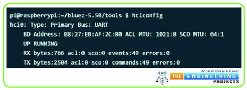
The hciconfig tool has informed us that the hci0 interface provides the Bluetooth functionality provided by the BT adapter. Yes, that user interface is what we'll be utilizing.
If there are any instances when we need to loop the interface, we can bring it down and put it back up again.

If the interface is acting erratically, try the reset procedure described above.
To locate nearby BLE devices and pair with them, we can use the hcitool program:
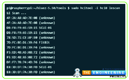
An LE Scan was requested above by calling the hcitool with the scan hci0. The MAC address of any adjacent devices is shown.
Let's start hooking up on BLE gadgets now that we know their addresses. Since we will also be changing the GATT settings on a BLE device, we will use the gatttool program. While hcitool can execute Traditional Bluetooth and BLE HCI instructions, it cannot control the GATT tool independently.
gatttool has an interactive and non-interactive mode of operation. With the console's interactive way, you may send commands and converse with the machine. You must exit the game to get back to the main menu.
It's crucial to prevent the command from exiting independently while performing it. If you interrupt a command with CTRL+C, the hci interface may enter an unexpected state. In that instance, cycling power to the interface off and on may be of assistance.

The preceding code is typical; however, the -t argument indicates whether the device's IP address is random or accessible to the public. Assigned IEEE media access control (MAC) addresses are used for public addresses. Addresses when the media access control (MAC) is set randomly, as is typically the case with BLE devices.
If you're having problems, try connecting to the device using public or random if you're having problems.
Reading/Writing Characteristics
Literacy in reading and writing to traits is a crucial skill. Using the gatttool's interactive features

Dwad

Enabling and Receiving Notifications
Another method for obtaining data from Bluetooth devices while using minimal power is subscribing to notifications. Any time a piece of hardware has something new to report—data or an alert—it can send a message.
The Client Config characteristic descriptor must be updated with the proper flags to enable notifications.

Using a Pi 4 as a Gateway
We touched on the Raspberry Pi's performance issues at the outset of this piece, and you may have noticed that the range is relatively restricted, depending on the device. It isn't the only thing to think about. Because of its narrow temperature range, the Raspberry Pi has some severe drawbacks. The operating temperature of the newest Raspberry Pi 4, which is 0 to 50 degrees Celsius, can only be used in climate-controlled environments. We've had more success with bespoke heatsinks and fans to boost performance, but testing is required before deployment can be assured.
Here are some things to keep in mind if you want to get the best outcomes possible from a Raspberry Pi deployment:
Reducing the quantity of data carried via Wi-Fi networks operating in the 2.4GHz range.
Using Ethernet or the 5GHz spectrum can help prevent interference.
Connecting and Installing Hardware
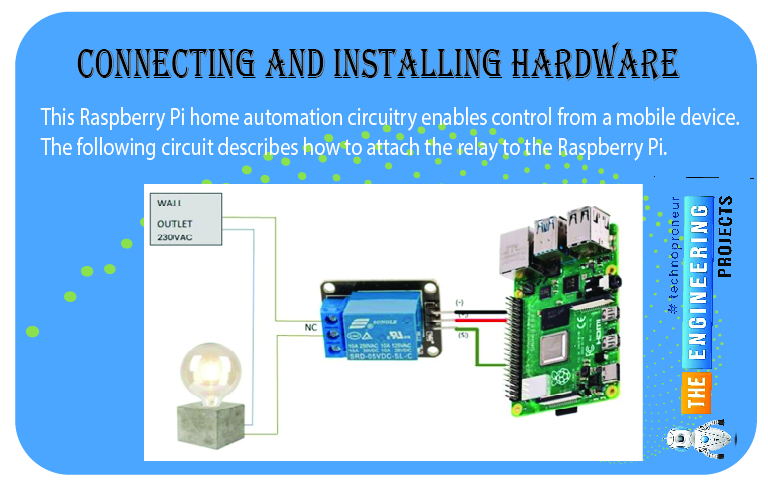
This Raspberry Pi home automation circuitry enables control from a mobile device. The following circuit describes how to attach the relay to the Raspberry Pi.
Instructions for bleuio_rpi_switch_example.py
Follow this step: Plug the BleuIO Dongle into your Raspberry Pi.
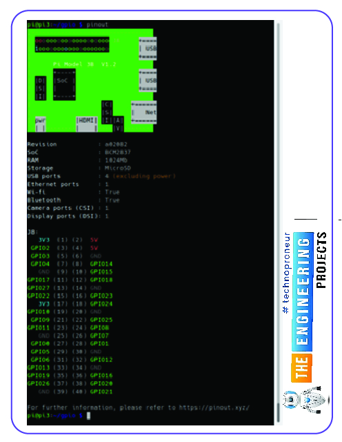
To use a specific GPIO pin, change the value of the switch variable in the script. (A graphical representation of the board's GPIO pins is available via the pinout command.)
Instructions for connecting to the BleuIO from mobile
- Get yourself Bluetooth Low Energy (BLE) scanning software that can pair with gadgets and transfer data back and forth? (Such as BLEScanner or nRFConnect)
- You can identify a BleuIO dongle by its blue and white branding.
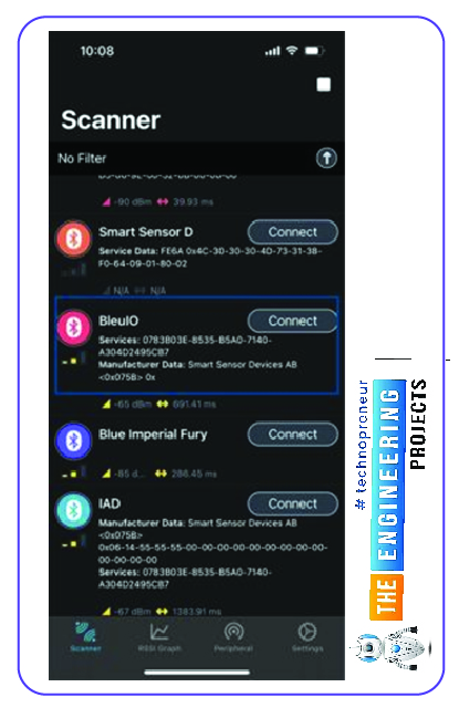
To begin, plug in the BleuIO dongle.
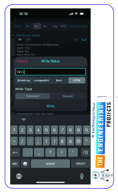
Write 0x01 to the Flow Control feature to make BleuIO listen for orders (UUID: 0783b03e-8535-b5a0-7140-a304d2495cb9)
The GPIO can now be controlled by writing to the Server RX Data attribute (UUID: 0783b03e-8535-b5a0-7140-a304d2495cba).
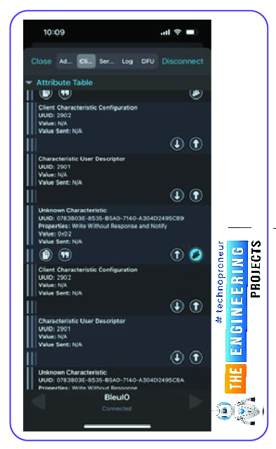
“SW=1” for ON
“SW=0” for OFF
Example Timer python code
# import GPIO and datetime
import RPi.GPIO as GPIO
import datetime
# set GPIO numbering mode and define output pins
GPIO.setmode(GPIO.BOARD)
GPIO.setup(37,GPIO.OUT)
GPIO.setup(38,GPIO.OUT)
GPIO.setup(40,GPIO.OUT)
# Turn lights on and off based on the time
try:
while True:
now = datetime.datetime.now().time()
if now.hour == 21 and now.minute == 5:
GPIO.output(40,True)
elif now.hour == 21 and now.minute == 6:
GPIO.output(38,True)
elif now.hour == 21 and now.minute == 7:
GPIO.output(40,False)
GPIO.output(38,False)
finally:
# cleanup the GPIO before finishing :)
GPIO.cleanup()
Source Code/Python Script
Here's the python code for controlling lights in your home with a smartphone app using a Raspberry Pi as a hub for automation.
import time
import serial.tools.list_ports
import serial
import RPi.GPIO as io
switch = 7 # Edit this to suit your setup! (7 = GPIO 04), use command pinout to show you the GPIO pins for the board graphically
io.setmode(io.BOARD)
io.setup(switch, io.OUT)
master_array = []
index = 1
dongle_port = ""
print("\nWelcome to BleuIO RaspberryPi Switch Example!\n")
print("\nPlease insert dongle...")
try:
while len(master_array) == 0:
m_ports = serial.tools.list_ports.comports(include_links=False)
for port in m_ports:
if str(port.hwid).__contains__("VID:PID=2DCF"):
master = port.device + " " + port.hwid
if master.__contains__("VID:PID=2DCF:6002"):
print("Found dongle in port: %s" % port.device)
master_array.append(master)
dongle_port = port
break
for dongle in master_array:
print("\nConnecting to BleuIO @ %s\n" % dongle)
time.sleep(0.5)
dongle_conn = Serial.Serial(
dongle_port.device,
115200,
timeout=1,
)
if not dongle_conn.is_open:
dongle_conn.open()
print("Starting Advertising...")
dongle_conn.write("AT+GAPDISCONNECTALL\rAT+DUAL\rAT+ADVSTART\rATI\r".encode())
read_tries = 0
dongle_resp = ""
while read_tries < 20:
dongle_resp = dongle_conn.readline().decode()
if "Not Advertising" in dongle_resp:
dongle_conn.write("AT+ADVSTART\r")
if b"Advertising\r\n" in dongle_resp.encode():
break
read_tries += 1
time.sleep(0.01)
if dongle_resp:
print("BleuIO is %s" % dongle_resp)
else:
print("ERROR! No response...")
exit()
print(
"Going into a loop, waiting for the signal to turn the switch on/off...\n(Press Ctrl+C to abort)."
)
while True:
try:
dongle_resp = dongle_conn.readline().decode()
if "SW=0" in dongle_resp:
print("Turn Switch off!")
io.output(switch, io.LOW)
if "SW=1" in dongle_resp:
print("Turn Switch on!")
io.output(switch, io.HIGH)
except KeyboardInterrupt:
if dongle_conn.is_open:
dongle_conn.write("AT+GAPDISCONNECTALL\rAT+ADVSTOP\r".encode())
dongle_conn.close()
io.cleanup()
print("\nBye!")
exit()
except Exception as e:
print("(ERROR: %s)" % (e))
Output

Conclusion
In conclusion, controlling household appliances with a Raspberry Pi 4 with Bluetooth Low Energy (BLE) capabilities is an efficient and hassle-free option. A Raspberry Pi 4 equipped with the appropriate hardware and software may connect with and remotely control various BLE-enabled devices.
Using a Raspberry Pi 4 and Bluetooth Low Energy (BLE), users may command their household appliances from their smartphone or a web interface, and the Pi will carry out the commands. This allows for a versatile and adaptable method of managing lights, thermostats, and smart plugs.
Home automation enthusiasts may find that programming a Raspberry Pi 4 with BLE to operate their household gadgets is a fun and rewarding do-it-yourself project. Developing a highly effective system that can improve the quality of one's life requires skill, expertise, and access to the necessary materials. In the following tutorial, we will learn how to buid an IOT-based weather station in pi 4.


