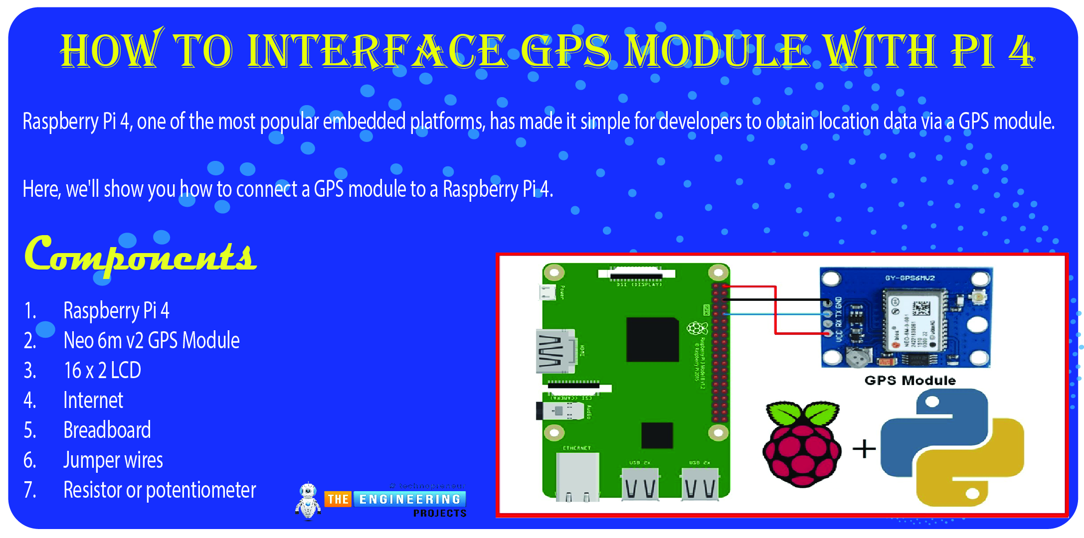
Welcome to the next tutorial of our raspberry pi four programming course. Before, we saw how to connect a Raspberry Pi 4 to a relay with four independent channels. To complement the relay circuit, we programmed a python script to turn on and off a single bulb. However, in this tutorial, we'll show you how to connect a GPS module to a Raspberry Pi 4.

Raspberry Pi 4, one of the most popular embedded platforms, has made it simple for developers to obtain location data via a GPS module, allowing them to create devices with a greater reliance on precise positioning. Because of the Raspberry Pi's impressive processing capabilities, this essay focuses on the exciting prospect of creating GPS-based projects using the same inexpensive GPS chips.
Since this project aims to retrieve location information (longitude and latitude) from a GPS module through UART and display it on a 16x2 LCD, this is yet another excellent chance to become acquainted with the 16x2 LCD and the Raspberry Pi.
Components
Raspberry Pi 4
Neo 6m v2 GPS Module
16 x 2 LCD
Internet
Breadboard
Jumper wires
Resistor or potentiometer
In addition, we'll install the GPS Daemon library and the 16x2 LCD Adafruit library later in this guide.
The Raspberry Pi 4 running Raspbian OS is being used in this example. You can find a rundown of the minimum necessary hardware and software in Raspberry Pi's introductory instruction.
How does a GPS module function?
The acronym "GPS" stands for "Global Positioning System," and it is used to determine the precise Longitude and Latitude of any point on Earth and the current UTC time. The core of every GPS tracking system is a GPS module installed in the vehicle. This gadget gets up-to-the-second satellite coordinates along with the time and date.
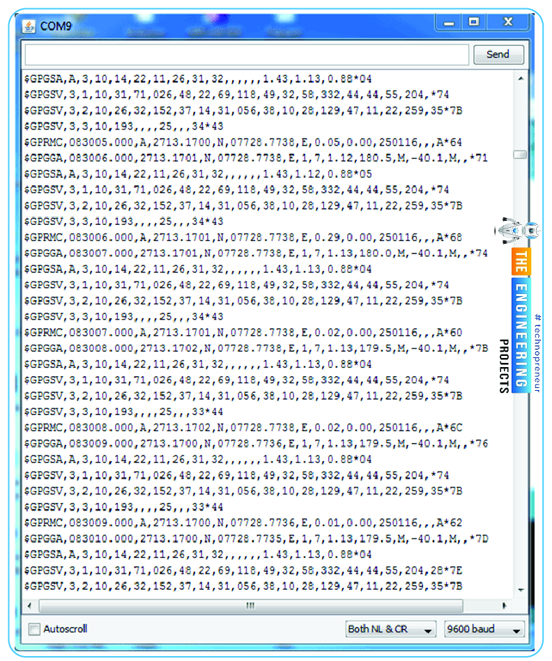
Using the NMEA protocol, a GPS module transmits a plethora of position-tracking data in real time, as shown below. The NMEA format includes multiple sentences, yet only one is necessary. Coordinates, time, and other pertinent data begin at $GPGGA in this phrase. This information is known as GPS Fix Data or Global Positioning System Geodetic Reference Frame Data.
We can determine its coordinates by using a simple count of commas in the $GPGGA string. If you locate the $GPGGA string and place it in an array, you can get the Latitude value two commas later and the Longitude value four commas subsequently. These coordinates for longitude and latitude can now be used in other datasets.
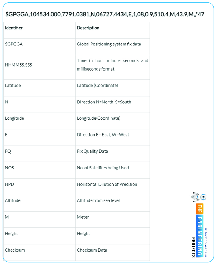
The $GPGGA String and its explanation are listed below.
$GPGGA,HHMMSS.SSS, latitude, N, longitude, E, FQ, NOS, HDP, altitude, M, height, M,, checksum data
The GPS module
You can use the NEO-6MV2 as your own personal GPS receiver everywhere you go. The GPS receiver communicates with the satellite network to determine its precise location. The device then sends forth serial data representing its current location, including its latitude and longitude.
The NEO-6 module uses a ublox-6 positioning engine with 50 channels and a TTFF of one second. The massive parallel time-space searches are made possible by the two million correlators in this GPS engine. As a result, it can rapidly locate satellites. The module's compact size also makes it a good fit for portable electronics that run on batteries.
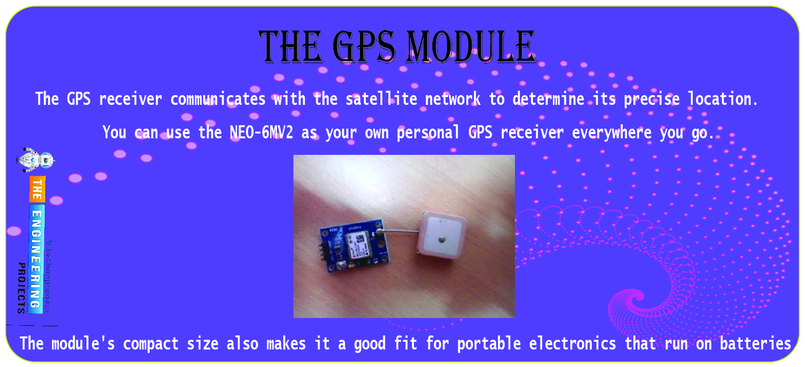
It takes a voltage between 2.7V and 3.6V to power the NEO-6M GPS modem. The NMEA protocols are used for the communication of GPS data. While NMEA is an industry-standard ASCII format, UBX is a proprietary binary format developed by u-blox.
Data can be transmitted using any I2C-compliant interfaces on the receiver chipset, including Universal Asynchronous Receiver Transceiver (UART), USB, SPI, or DDC. There are three configuration pins on the chip. Pin CFG-GPS0 is used to set the power mode at boot.

Choose between the NMEA and UBX protocols for transmitting GPS data using CFG COM0 and CFG COM1.

This module employs a NEO-6 modem that has already been configured for serial (UART) output and NMEA encoding GPS data.
By setting the config pins CFG COM0 and CFG COM1 to HIGH, the GPS data is transmitted via the NMEA protocol at 9600 bps. The above table demonstrates that the NMEA data in this setup contains GSV, RMC, GSA, GGA, GLL, and VTG signals.
Here is a pin diagram showing the module's four available channels:
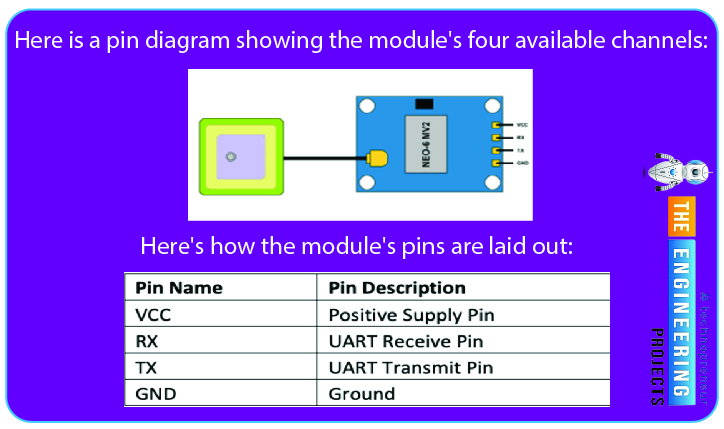
The module's top update rate for its navigation system is 5 Hz. So, in no more than 0.2 seconds, a controller can retrieve the Gps coordinates from the modem.
The 32-second cold start, 23-second warm start, and 1-second hot start times are all measured when the modem is turned on. Getting the first GPS reading takes 32 seconds because the module is set up for a cold start.
The module includes an external antenna with a frequency of -160dBm. Both an EEPROM and real-time clock (RTC) are built into the module, and the module also features a battery for backup. Temperatures from -40 to 85 degrees Celsius are within the NEO-6M modem's operational range.
Getting a Raspberry Pi set up for GPS communication
To get started, I'll assume you're familiar with the Raspberry Pi and know how to install an operating system, find your IP address, and launch a terminal app like PuTTY. If you have any questions or need assistance, please let me know in the comments area.
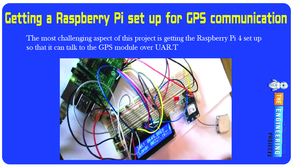
The most challenging aspect of this project is getting the Raspberry Pi 4 set up so that it can talk to the GPS module over UART; trust me, I know; this is the first time I've done it, and it took me a few tries to get it right.
Functioning of the UART in Communication
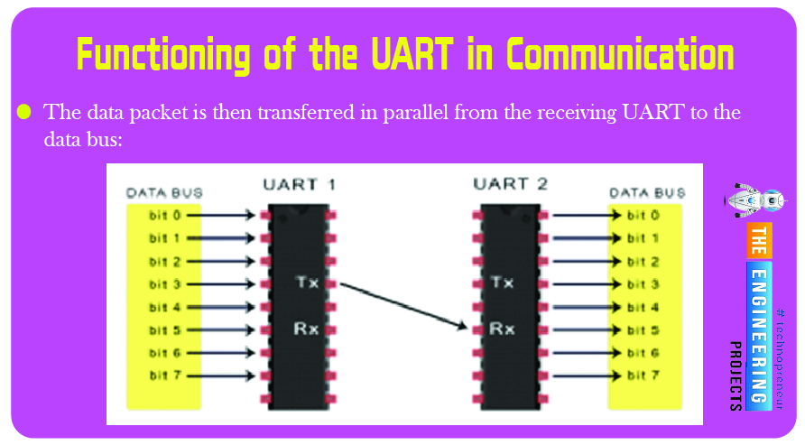
UART communication involves a one-to-one connection between two UARTs. One UART does the serial-to-parallel conversion for data coming from a CPU and then sends that serial data to another UART, which does the reverse for data coming into its receiving device. When connecting two UARTs, you must use two wires to send and receive data. As information is transmitted from one UART to another, it travels from the broadcasting UART's Tx pin to the receiving UART's Rx pin.
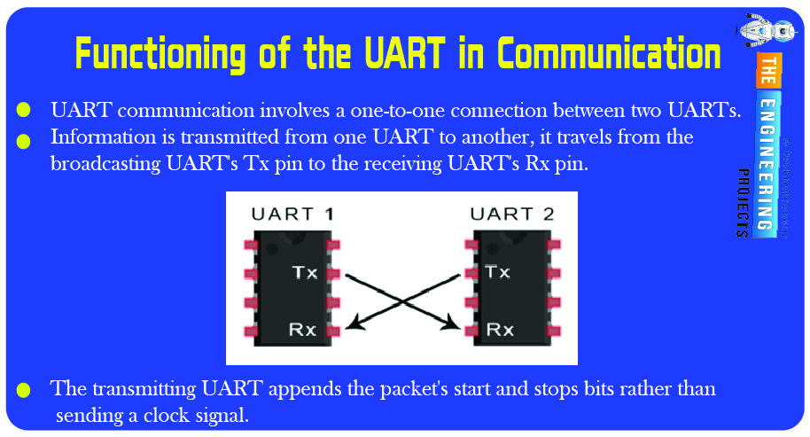
The bits sent out by the sending UART are not necessarily in sync with the bits sampled by the receiver UART since UARTs send data asynchronously. The transmitting UART appends the packet's start and stops bits rather than sending a clock signal. This information tells the receiving UART where to begin reading the data packet and where it should stop.
Once the receiving UART recognizes a start bit, it will begin decoding the incoming data at the pace determined by the baud rate. The speed of information transmission, in bits per second, is referred to as the "baud rate" (bps). The baud rate of both UARTs must be roughly equivalent. Bit timing inaccuracies can occur when the baud rate difference between the sending and receiving UARTs exceeds 10%.
The data packet structure being transmitted and received by both UARTs must be identical.
The data for transmission arrives on a data bus and is picked up by the UART. To communicate with the UART, devices like the CPU, RAM, and microcontroller use a data bus. The transmitting UART receives data in a parallel fashion from the data bus. The data packet is created when the transmitting UART takes the parallel data from a data bus and adds a stop bit, a parity bit, and a start bit. The packet's data is sent out serially, one byte at a time, through the Tx pin. A data packet is sent and received serially through the Rx pin on the receiving UART. The UART decodes the data and restores it to its original parallel format, discarding the stop bit, parity bit, and start bit along the way. The data packet is then transferred in parallel from the receiving UART to the data bus:
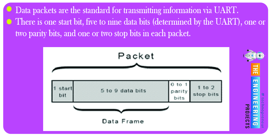
Data packets are the standard for transmitting information via UART. There is one start bit, five to nine data bits (determined by the UART), one or two parity bits, and one or two stop bits in each packet.
The Raspberry Pi includes a PL011 and a small UART as onboard UARTs. Because of the unique hardware building pieces they employ, their overall performance and other attributes will vary slightly. Contrarily, the raspberry pi's tiny UART is utilized for the Linux console output, while the PLO11 UART is linked to the wireless/Bluetooth module.
The PLO11's higher implementation level makes it the superior of the two UART options. Accordingly, we'll use an overlay in the most recent version of Raspbian OS to turn off the Bluetooth module on the PLO11 UART for this project.
Step 1: Update the Raspberry Pi
To get started on any new project, I always start by upgrading the raspberry pi. Therefore, let's do the standard procedure and execute the commands below;

sudo apt-get update
sudo apt-get upgrade
and then restart the computer using;

sudo reboot
Step 2: Set up the UART
Within this context, we will initially modify the /boot/config.txt file. Please use the following instructions to accomplish this:

sudo nano /boot/config.txt
Place the following lines at the end of the config.txt file:
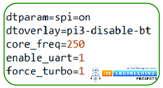
dtparam=spi=on
dtoverlay=pi3-disable-bt
core_freq=250
enable_uart=1
force_turbo=1
You can leave with Ctrl+X and save with Y + Enter.
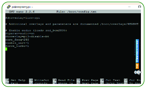
Incorrect settings could prevent your Raspberry Pi from starting up, so please double-check everything.
Why are we issuing these commands? Because force turbo causes UART to operate at its maximum core frequency, which we have set to 250 MHz. This is done to protect the reliability and validity of the received serial data. Force turbo=1 will now void your Raspberry Pi's warranty, but other than that, it's safe to use.
We are disabling Bluetooth on the Raspberry Pi 3 using the dtoverlay=pi3-disable-bt so that we may use the full power of the UART on ttyAMAO rather than the small UART on ttyS0.
The second step in configuring the UART is to modify the boot/cmdline.txt file.
Before making any changes to the cmdline.txt file, you should save a copy in case you need to revert to the original version. A few ways to accomplish this are;

sudo cp boot/cmdline.txt boot/cmdline_backup.txt
sudo nano /boot.cmdline.txt
Substitute the following for the current text;

dwc_otg.lpm_enable=0 console=tty1 root=/dev/mmcblk0p2 rootfstype=ext4 elevator=deadline fsck.repair=yes rootwait quiet splash plymouth.ignore-serial-consoles
save your work and exit.
After this is complete, another system reboot is required before the new settings may take effect (sudo reboot).
Step3: Disable the Pi 4 Serial Getty Service
Next, we'll issue a command that will block the Pi's serial getty service from starting automatically upon reboot:

sudo systemctl stop serial-getty@ttyS0.service
sudo systemctl disable serial-getty@ttyS0.service
If you ever need to turn it back on, use these commands.

sudo systemctl enable serial-getty@ttyS0.service
sudo systemctl start serial-getty@ttyS0.service
Reboot your pi 4.
Step 4: Activate ttyAMAO:
Now that ttyS0 is no longer active, we can turn on ttyAMAO.

sudo systemctl enable serial-getty@ttyAMA0.service
Step5: Install Minicom and pynmea2:
We'll establish communication with the GPS unit and decipher its readings using minicom. In addition, we will use it to ensure that our GPS component is functioning correctly. Daemon software GPSD is an alternative to minicom.

sudo apt-get install minicom
We'll employ the pynmea2 library to quickly and conveniently process incoming information. Installing it necessitates;

sudo pip install pynmea2
Step 6: Install the LCD Library:
The AdaFruit library will serve as the basis for this tutorial. While the library's primary target was AdaFruit displays, it can also be used with HD44780-based display boards. In such a case, your display should function normally.
The library should be cloned and installed immediately. to conduct a cloning run;

git clone https://github.com/adafruit/Adafruit_Python_CharLCD.git
Go to the location where the clone was made and install it.

cd ./Adafruit_Python_CharLCD
sudo python setup.py install
It's time for another restart so we can move on to plugging in the parts.
Circuit diagram
Referring to the schematic below, attach the GPS Module and the Liquid crystal display to the Raspberry Pi.
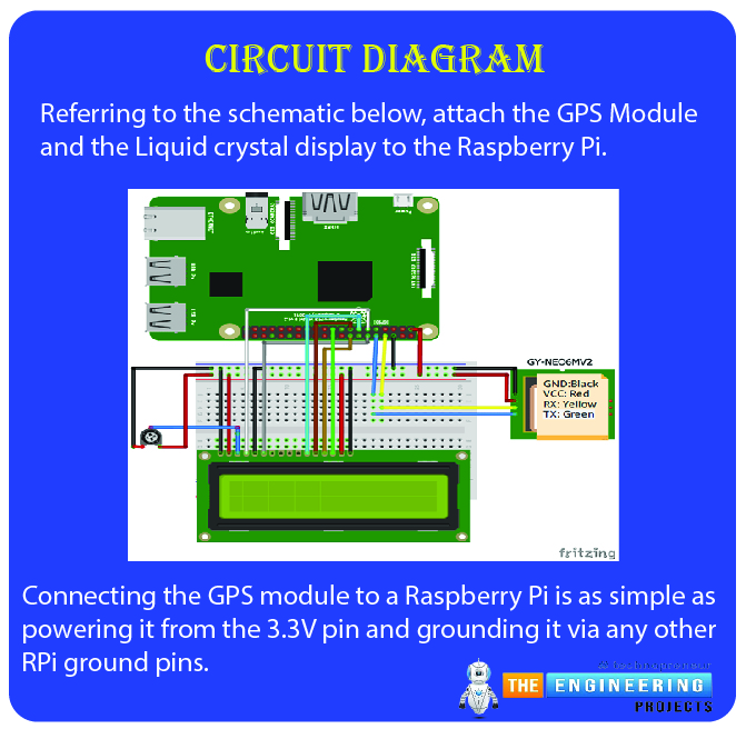
Connecting the GPS module to a Raspberry Pi is as simple as powering it from the 3.3V pin and grounding it via any other RPi ground pins.
Following this, link the module's transmit (TX) pin to the Raspberry Pi's receive (Rxd) UART pin (board pin 10).
Testing the GPS module
Before we jump into the python script, it's best to use minicom to verify the GPS module's connectivity. Type the command and hit Enter.

sudo minicom -D/dev/ttyAMA0 -b9600
Where 9600 is the baud rate the GPS module uses to transmit data. Once we have verified that our GPS and RPI can exchange data with one another and script development can begin.
Cat can also be used for the test.

sudo cat /dev/ttyAMA0
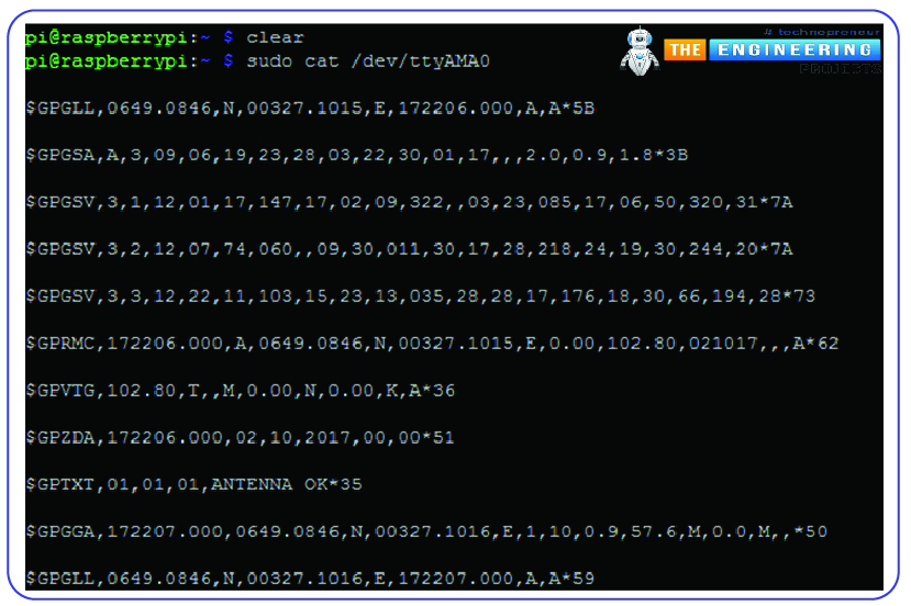
All of the previously discussed NMEA sentences will appear in Window. As shown in the figure below, a module's status LED will begin blinking if the GPS receiver detects satellites in the sky and begins to fixate on its location.
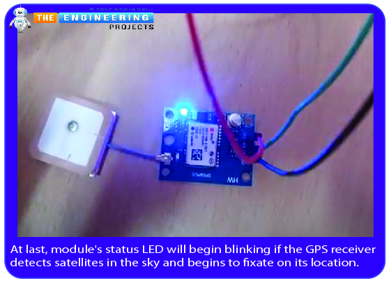
Now that everything has been set up, we can put it through its paces. Your GPS may need to be outside to acquire a good satellite lock (often, three or four are required; however, I was able to use mine indoors).
Complete code
import time
import serial
import string
import pynmea2
import RPi GPIO as gpio
#to add the LCD library
import Adafruit_CharLCD as LCD
gpio.setmode(gpio.BCM)
#declaring LCD pins
lcd_rs = 17
lcd_en = 18
lcd_d4 = 27
lcd_d5 = 22
lcd_d6 = 23
lcd_d7 = 10
lcd_backlight = 2
lcd_columns = 16 #Lcd column
lcd_rows = 2 #number of LCD rows
lcd = LCD.Adafruit_CharLCD(lcd = LCD.Adafruit_CharLCD(lcd_rs, lcd_en, lcd_d4, lcd_d5, lcd_d6, lcd_d7, lcd_columns, lcd_rows, lcd_backlight)
port = "/dev/ttyAMA0" # the serial port to which the pi is connected.
#create a serial object
ser = serial.Serial(port, baudrate = 9600, timeout = 0.5)
while 1:
try:
data = ser.readline()
except:
print("loading")
#wait for the serial port to churn out data
if data[0:6] == '$GPGGA': # the long and lat data are always contained in the GPGGA string of the NMEA data
msg = pynmea2.parse(data)
#parse the latitude and print
latval = msg.lat
concatlat = "lat:" + str(latval)
print concatlat
lcd.set_cursor(0,0)
lcd.message(concatlat)
#parse the longitude and print
longval = msg.lon
concatlong = "long:"+ str(longval)
print concatlong
lcd.set_cursor(0,1)
lcd.message(concatlong)
time.sleep(0.5)#wait a little before picking the next data.
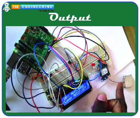
Output
Conclusion
This tutorial covered the basics of installing a GPS tracker on a Raspberry Pi 4. What we know about UART and the NMEA protocol has expanded as well. Numerous new possibilities for the exploration of the idea are now available. You could, for instance, construct a system for tracking vehicles, drones, or the weather. In addition to being inexpensive and simple to install, GPS modules are becoming increasingly popular. They can be frustrating because of their slow data extraction and spotty reception. However, they perform wonderfully in the open air. Next, we'll look at how to interface the BMP180 air pressure sensor to a Raspberry Pi 4.


