Hello friends, welcome back to our tutorials on PLC ladder logic programming. Today we will talk about batch process control and take one project from our factory to understand, implement, and simulate. So without any further delay, let’s jump into the tutorial by asking what is batch process is if it is different from other online processes. Well! The batch process is defined as a process that starts by operating continuously till the end of the cycle without any interaction with the users. For you guys, it’s cool to know that most of the processes you might meet in the industry of batch-type processing. Do you like me to give an example? Well! The Silo cement process is a batch process, and food and beverages manufacturing are also good examples of batch processes. So what do we have today of the batch process? It’s a batch-mixing process in which we mix liquids with a mixer. The process utilizes a couple of sensors and actuators to be performed, as we will see in the next pages. So let’s go further in our project.
Mixing batch process
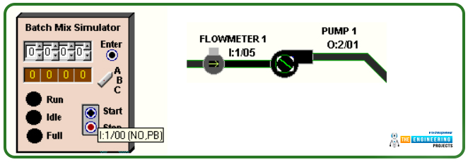
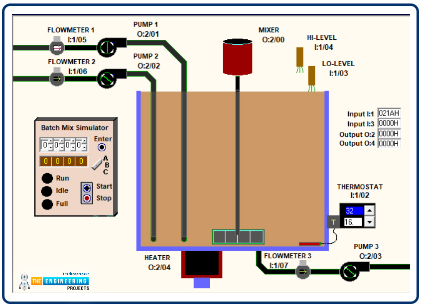
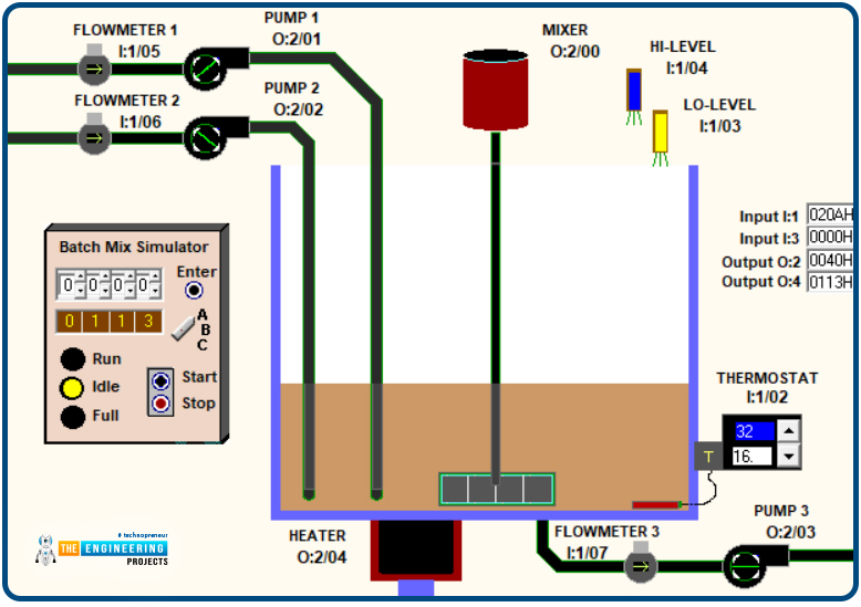
Figure 1 shows a beautiful scene of the process that shows all components, including actuators, sensors, switches, and indicators. As you can see, friends, two pine lines supply the liquids to mix. For each line, a flowmeter switch tells the amount of liquid filled so far. It also shows one pump for each line to draw the liquid from the source to the mixing tank. Also, the liquids are mixed in the middle of the tank thanks to a mixer installed vertically in the middle of the tank. In addition, you guys notice the proximity switches installed on the top right of the tank to detect the level of the liquid .inside the tank to recognize two levels of the liquid. One is the low and the other for detecting the high liquid level inside the tank. Also, at the very bottom of the tank, you can see another pump installed underneath the tank at the center to drain the mixed liquid out from the tank. And also, the drainage pipe has a flowmeter switch to determine the amount taken out from the tank. On top of that, on the left, you see the control panel that helps operators start and stop. Set parameters of the process in addition to showing the process status throughout the process run, idle, stop status, the amount of liquid in the tank, and the amount of liquid drawn from each line. I know you are now gossiping ohh, that time we have a large project and too many things to control. No, no, brothers, it’s a simple process but let us go through the requirements and divide the work into parts and go do part by part together.
Mixing batch process operation
Every process has its logic or philosophy or the logical narrative that the client will tell or the customer. Your turn is to listen to him and ask for every details to make sure you have everything you need to start. Please validate your understanding and question your client about everything you need to start with a good understanding of the process and the requirements. The process between our hands to do today is nothing more than a batch process performed manually by the operator’s fingers. You will make it automated using PLC so that the operator will narrate to you what he does from the start to the end of the process cycle to complete the process. First, he starts by hitting the commencing button that starts the pumps P1 and P2 to draw liquid until the level of liquid in the tank reaches 90%, at which we should mark the tank as full and stop the pumps and the filling process. The next stage is to command the mixer to run for a while, which is decided by the client. In our project, we were told to run the mixer for 8 seconds. Afterward, the drainage pump runs to take out the mixed liques until the tanks are empty. At that time, we can repeat the process by hitting the start push button again for another cycle or continuously running cycle after cycle automatically. Also, you need to know the operator can stop the cycle at anytime. The indicator and BCD screen should tell the operator the current status and the amount of liquid input and output to and from the tank.
The process inputs and outputs
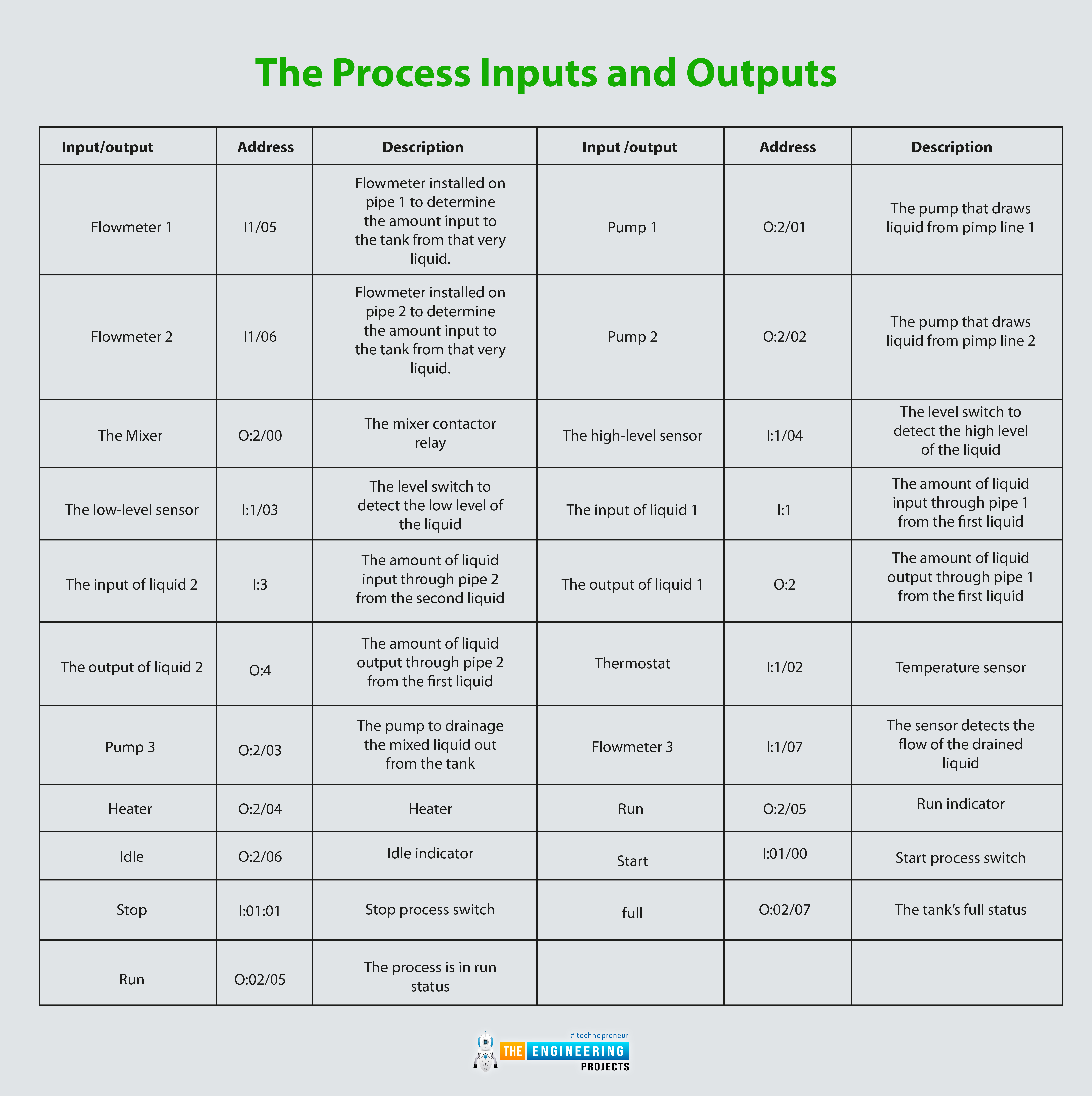
Table 1 lists all inputs and outputs of the mixing batch process. The first column shows the name of the Ios, the 2nd column presents the IO addresses, and the 3rd column informs a description of the IO.
Input/output |
address |
description |
Input /output |
address |
Description |
Flowmeter 1 |
I1/05 |
Flowmeter installed on pipe 1 to determine the amount input to the tank from that very liquid. |
Pump 1 |
O:2/01 |
The pump that draws liquid from pimp line 1 |
Flowmeter 2 |
I1/06 |
Flowmeter installed on pipe 2 to determine the amount input to the tank from that very liquid. |
Pump 2 |
O:2/02 |
The pump that draws liquid from pimp line 2 |
The Mixer |
O:2/00 |
The mixer contactor relay |
The high-level sensor |
I:1/04 |
The level switch to detect the high level of the liquid |
The low-level sensor |
I:1/03 |
The level switch to detect the low level of the liquid |
The input of liquid 1 |
I:1 |
The amount of liquid input through pipe 1 from the first liquid |
The input of liquid 2 |
I:3 |
The amount of liquid input through pipe 2 from the second liquid |
The output of liquid 1 |
O:2 |
The amount of liquid output through pipe 1 from the first liquid |
The output of liquid 2 |
O:4 |
The amount of liquid output through pipe 2 from the first liquid |
Thermostat |
I:1/02 |
Temperature sensor |
Pump 3 |
O:2/03 |
The pump to drainage the mixed liquid out from the tank |
Flowmeter 3 |
I:1/07 |
The sensor detects the flow of the drained liquid |
Heater |
O:2/04 |
Heater |
Run |
O:2/05 |
Run indicator |
Idle |
O:2/06 |
Idle indicator |
Start |
I:01/00 |
Start process switch |
Stop |
I:01:01 |
Stop process switch |
full |
O:02/07 |
The tank’s full status |
Run |
O:02/05 |
The process is in run status |
Batch Mixing Process with Ladder Logic
That can not be counted as a large-scale project. However, let’s deal with it as a large one. So, professionally will take it into parts to simplify our mission. The project will be divided into three small projects, So let us go through each part until we get the whole process done.
The filling process
In the filling part, we need to pump P1 by hitting the start push button until the level in the tank reaches full status when the liquid level becomes 90%. At then, pump P1 should be stopped. You see, guys, dividing the whole process into small, simple sub-processes make it easier to implement.
Implementation and testing
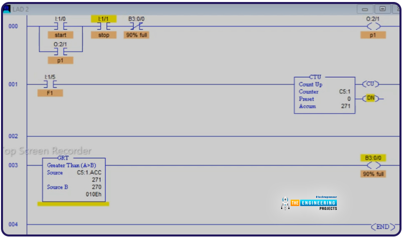
Figure 3 shows the ladder logic of the first part that controls the filling process. You see, guys, it simply latches the pump output O:2/1 by using the start push button and stops by either hitting the stop push button to stop the run or by reaching the full position by counting the generated pulses from input I:1/5 till it counts what is equivalent to 90% of the high level of the tank. So let us test that part and see if it is functioning well or if we need to amend the code we wrote.
Testing part 1 for the filling tank
Success is the result of testing part 1, as in figure 4. You see, guys, the tank kept filling by latching the pump P1. But when the counter accumulator reports 90% of the tank is full, the full flag stopped pump P1 as it is designed for that part. Now let’s move to the next part.

Emptying the tank
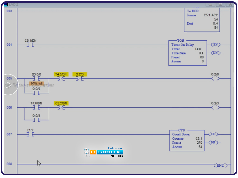
In this second part of the project, we are required to control the emptying process of the tank. The sequence is like when the full status of the tank level is reached, which is already achieved in part 2, the mixer should be activated for 8 seconds, and then the pump P2 will be energized to drain the tank till reaching to zero level of the tank at then the pump P2 will be stopped. So let us discuss the ladder code of that part.
The ladder logic of the emptying process
Figure 2 shows the code we wrote to implement the draining process. We started displaying the code from rung three because rungs 1 and 2 are just like part 1 to fill the tank. In Runge 3, we display the tank level by copying the counter accumulator value C5:1.ACC to the O:4 output of the BCD to 7 segment display. In Runge 4, we use timer T4:0 to count the 8 seconds during which the mixer will run, as in Runge 5. After the 8 seconds of mixing, pump P3 is energized to drain the mixed liquid as in runge 6. When you empty the tank, note down till reaching zero level as in Rung 7. At that time, pump P3 will have been stopped. I hope testing this stage goes okay, as we will check in the next section.
Testing the emptying process of the mixing batch process
As you see in figure 6, the emptying process is okay. The liquid is drained from the tank starting from the full position till reaching zero level position thanks to control of the drainage pump P3.
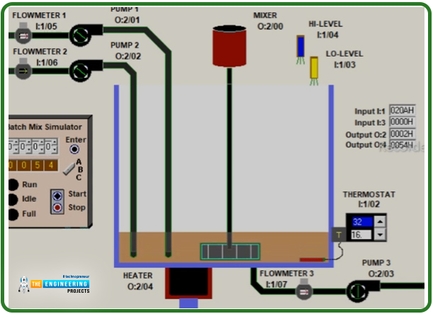
Figure 7 shows that the draining process continues till the liquid is drained from the tank.
The last part of having a continuous operation
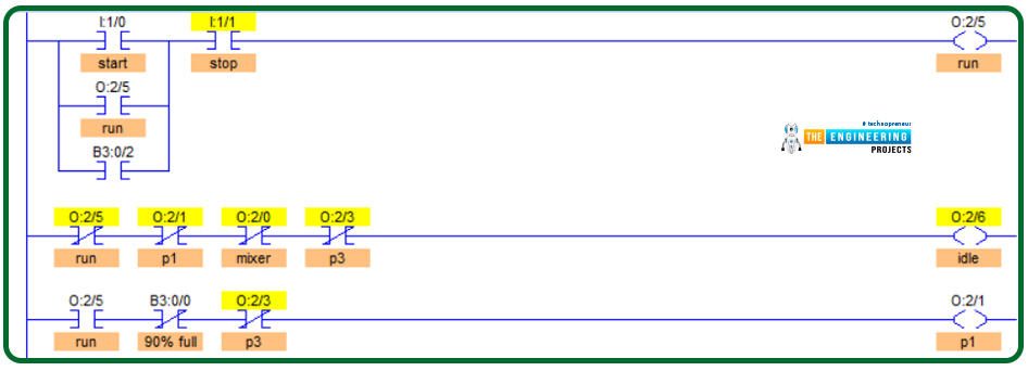
After completing the whole batch process cycle, starting from filling the tank and ending with draining the liquid out from the tank, it is required to let the process run automatically, meaning the cycle repeats forever unless the operator requests a stop. Figure 8 shows the ladder logic code we added to automate the cycle. The amendment we have added in Rung 1 shows that to start the process by hitting the start push button; we added a flag B3:0/2 that indicates the end of the last cycle to start a new cycle automatically. Also, we have added in rung 2 the code for the Idle process status indicator when there is no activity of either the mixer or pumps.
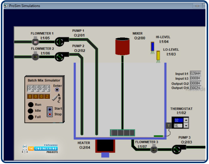
Testing the last stage
Figure 9 shows the idle status when there are no activities and the mixer and pumps are stopped.
I could not find a way to show you the continuity of the cycle, which is the target of the last part, because images can not do that. Instead, it should be through videos. So I hope you go through this tutorial and write the code or even your code and enjoy running the project on the simulator to see the cycle run autonomously. Thanks, my friends, for following me till that point on this tutorial, and I hope to meet again soon with a new exciting one.


