Hello friends, after completing that basic part of ladder logic programming, let us today go through one topic which is not essential to know to complete a PLC ladder program but it is important t have our code readable program and reusable pieces of code. That could happen by using what so-called a subroutine. So what is a subroutine?
Well, it is a piece of code that includes a few rungs to perform specific tasks. that piece of code can be reused numerous times through the program when we need to call it for performing that task. That subroutine enables us to structure our code like building blocks so that the program will be readable very easy and also reusable later in other projects. The idea of dividing the program into routines to apply the divide and conquer technique is very crucial to ease the coding of your program especially when it comes to the large-scale program which is the common cause in the best industry practice.
Each routine achieves one specific task and they are integrated to accomplish the whole mission. By programming in that way, the code is more readable and reusable meaning that one routine could be called many times instead of keeping repeating the lines of code or ladder rungs everywhere we need it. In this tutorial, we are going to be very familiar with subroutine-based programming including different ways to call a subroutine and the instructions that are used for handling subroutines. And yes we are going to practice examples that program that subroutines in ladder logic so let's get started.
Types of routines
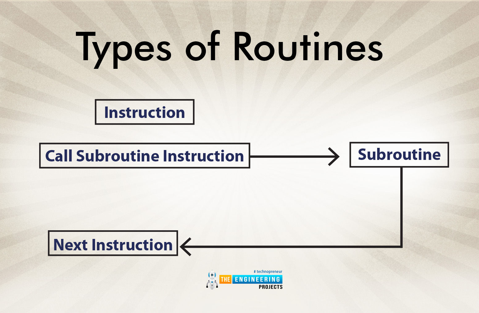
Routines can be classified into two main types: the calling routines that call subroutines. And routines that are being called. Figure 1 shows the very typical scenario of calling one subroutine. It shows the scenario when the calling routine reaches the calling instruction when the subroutine is being called with the value of the parameter passed by the calling routine and then the subroutine has a return instruction to take the execution to the following instruction of the calling instruction. So you can imagine the calling instruction is in the calling routine which is mostly the main program and the called subroutine is responsible to return the control or the execution point to the instruction next to the calling instruction.
Passing parameters
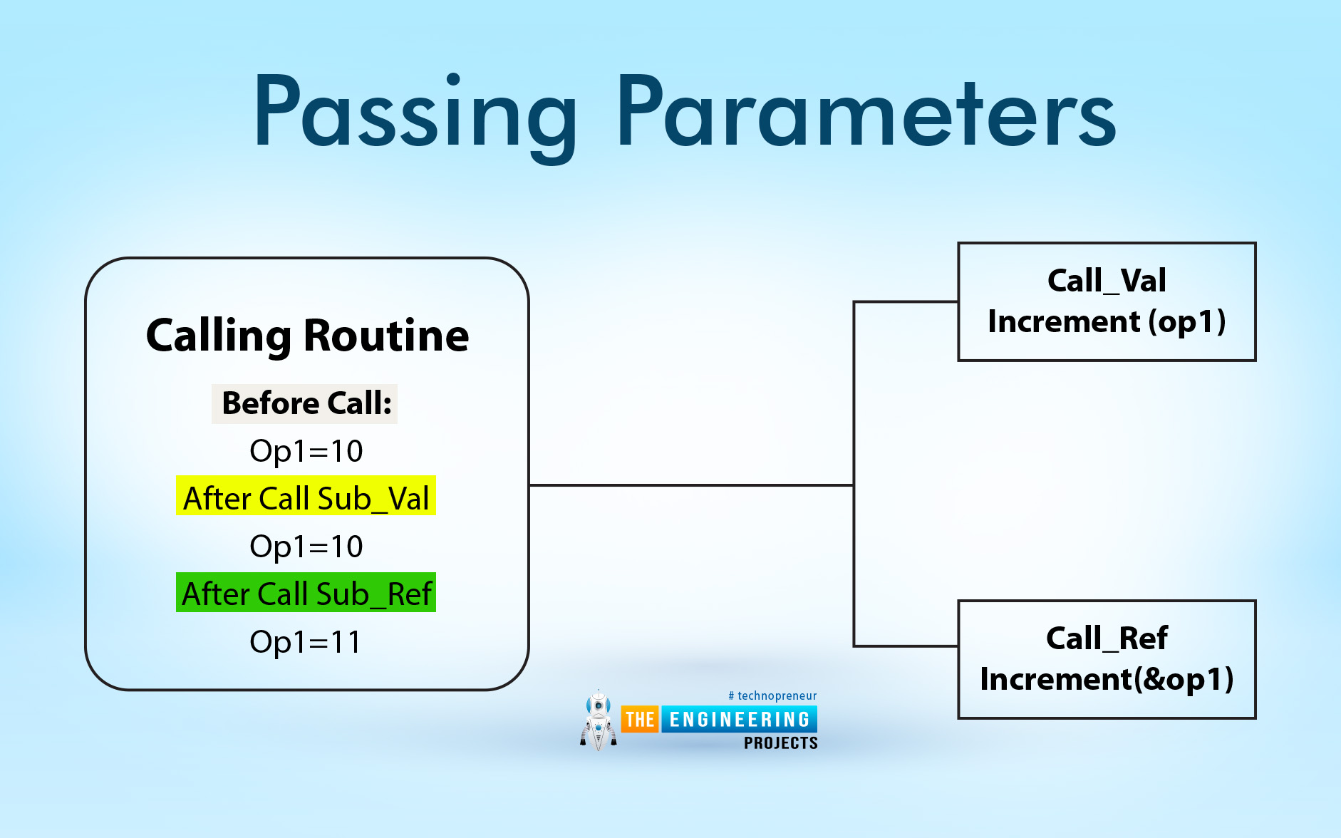
There are two main ways for passing parameters between the calling routine and the subroutine that is being called. The two ways are calling by value and calling by reference. In the calling by value method, the calling routine passes a copy of the original parameters so the called subroutine works on a copy. Therefore, there are no changes could happen to the original parameters in the calling routine. In contrast, in the second method which is called call by reference, the parameters are shareable between the calling routine and the subroutine that is being called. So, changes happened to the parameters but the called subroutine reflected on the original ones. Figure 2 depicts a case scenario of the two types of passing parameters. In that very example, the main routine calls subroutine “Call_Val” to apply an increment of operand “Op1” passing the parameter Op1 using the method “calling by value” while it calls “Call_ref” to do the same process but in that case, it passes parameter Op1 by using the method of “calling by reference”. As you can see, in the case it uses the “calling by value” method, it does not change the value of parameter Op1 because it uses a copy of the parameter and increments that copy not the original parameters. On the other hand, when it has used the other method, “calling by reference”, to increment the same parameter Op1, it does change the original operand because it uses a reference that points to the original parameter address. In another word, calling a subroutine based on a call by value works on a copy of the parameters and does not change the original variables while calling by reference works on the originally passed parameters so it does change the parameters. The advantage of calling by reference is saving the memory as it does not need an instance of the variables or a separate data block. On the other hand, calling by value needs to have a separate data block to include that copy of passing parameters. However, it can be called many times with a separate copy without any conflicts.
Program sequence:
Figure 3 shows the program sequence when using multilevel branching using subroutines. For example, the main module keeps carrying out the network net1, and net2, and it calls the subroutine “Sub x” in-network net3. Then subroutine “sub x ” starts executing from network net1 to net3 at which, it calls subroutine “Sub y”. Then subroutine “Sub y” carries out starting from the network “net 1”, and network “net 2” calls subroutine “Sub a”. You can notice subroutine “Sub a” returns to the calling routine “Sub y” which returns to subroutine to its calling routine “Sub x” which returns to its calling routine which is the main routine. So, you can notice how many levels of subroutine calls? Yes, they are a lot. But, it is recommended to be as much as needed for two reasons. First, many branching causes some headaches in processing in terms of memory and time. Memory is represented in the data block that is needed for each subroutine every single branching or subroutine calling and time is represented in extra instructions of calling and returning and stacking data related to the called routine and the returning addresses.

Subroutine instructions
There are two main instructions used for calling a subroutine and returning to the calling routine. Figure 4 shows the network rung that calls a subroutine called “Auto Mode”. It is going to call the subroutine at any time when the “System OK” memory contact MB180 is true. So I hope you can feel now how your program is more organized and readable when you go through the main program and easily can catch what the program does by reading the names of the called subroutines. Exactly, having a meaningful name for subroutines is very important to give the advantage of the readability of your program. So, my friends please make sure you chose a purposeful name for your subroutines.

Also fig. 5 shows the network rung that represents the returning command to the calling routine. It shows when the alarm is true represented by memory contact MB32 and pump status “Stop Pump” represented by memory bit64, the return command will be enabled for returning the execution point to the network just next to the calling network in the calling program. For example, if the calling network is at rung number 3, then the return command in the subroutine will return the execution at rung number 4 in the calling routine. By the way, in most cases of ladder logic programming, you might not find a return instruction because it is inherently performed by completing the called subroutine but we just include it here as in fig. 5 to show up how the process of calling a subroutine and returning to the calling routine.

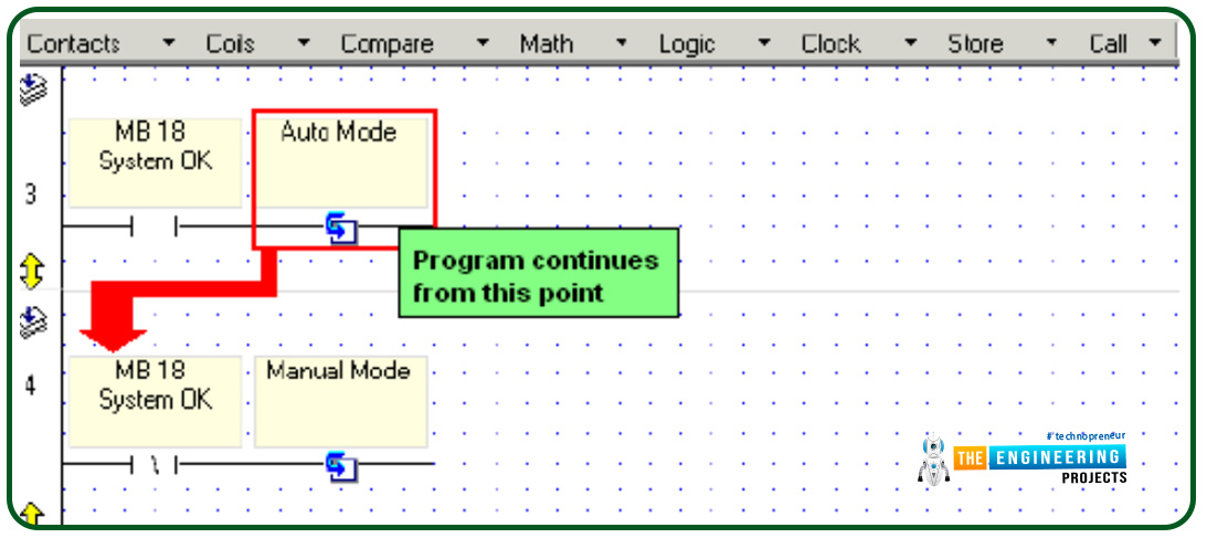
Figure 6 depicts the whole image of the scenario of calling one subroutine. In rung 3, a subroutine called “Auto mode” is being called by having the memory contact MB18 true. Then after that subroutine, “Auto mode” is completed it returns to the calling routine at the next rung to the calling rung which is in this case example rung number 4. As we stated earlier, you can notice that there are now returning instructions but automatically, the called subroutine returns to the calling routine at the instruction just next to the calling instruction.
Practicing Subroutine in ladder logic
My friends, let us go to our lab as usual and do some hands-on practicing subroutine using the simulator. But before going further in practice subroutine we want to elaborate on the different types of subroutines in Siemens programming. Table 1 compares the subroutine implementation based on function and function block. It shows that subroutine can be implemented by either function FC or function block FB. And both ways can use input, output, and in-out parameters.
FC does not use static data or data block (DB) while FB uses DB and passing parameters by making an instance of the variables which is calling by value. FC passes the parameter by pointing to the address of the variable which calling by reference technique.
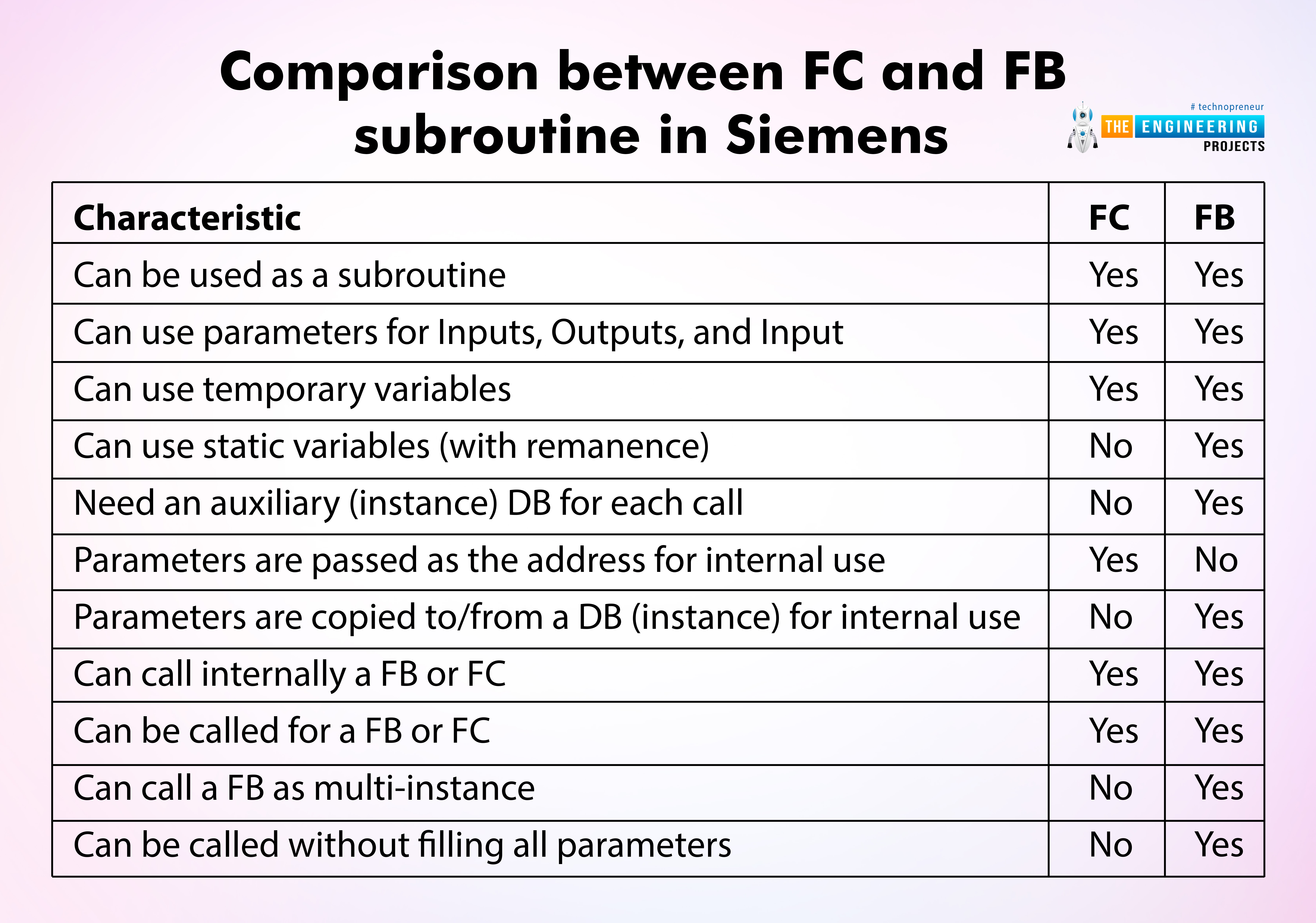
Table 1: Comparison between FC and FB subroutine in Siemens
Characteristic |
FC |
FB |
Can be used as a subroutine |
Yes |
Yes |
Can use parameters for Inputs, Outputs, and Input |
Yes |
Yes |
Can use temporary variables |
Yes |
Yes |
Can use static variables (with remanence) |
No |
Yes |
Need an auxiliary (instance) DB for each call |
No |
Yes |
Parameters are passed as the address for internal use |
Yes |
No |
Parameters are copied to/from a DB (instance) for internal use |
No |
Yes |
Can call internally a FB or FC |
Yes |
Yes |
Can be called for a FB or FC |
Yes |
Yes |
Can call a FB as multi-instance |
No |
Yes |
Can be called without filling all parameters |
No |
Yes |
Subroutine in ladder logic programming
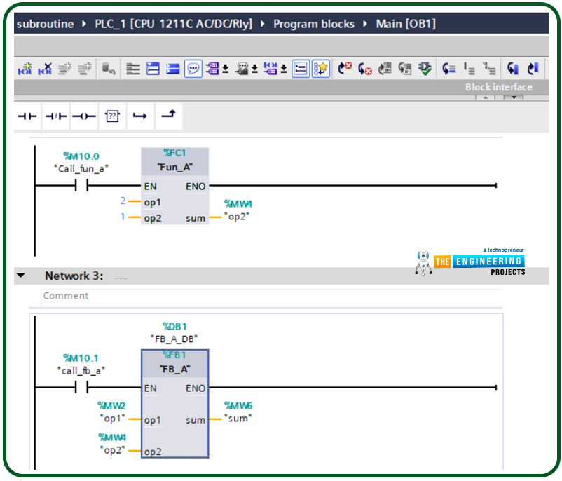
Again, there are two ways of calling a subroutine in Siemens ladder programming as shown in fig. 7. We have developed a sample ladder program that calls a simple subroutine to add two input operands. In the first rung, it uses function “FC1” called “fun_A” and in the second rung, it utilizes a function block FB1 called “FB_A” as you can notice function block uses a data block instance for passing a copy of the operands while function FC does not use a data block and uses the address of the input and output parameters.

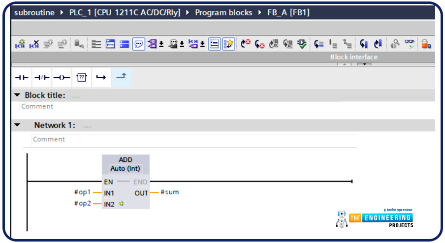
Figure 8 shows the function block FB_A. the function block has two input operands which are “op1” and ‘’op2” and one output operand which is “sum”.
Because the function block passes parameters as copies or instances, fig. 9 shows the related data block DB1 which contains the parameters of the function block. It is composed of many structures for holding input, output, input, and static data as well.

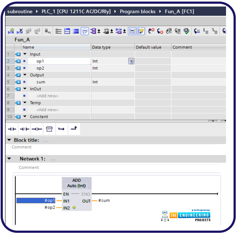
On the other hand, the function uses the addresses of the parameters. Therefore, it does not need a data block as shown in fig. 10. It uses many structures to pass input, output, input, temporary, and constant data types.
Simulation work
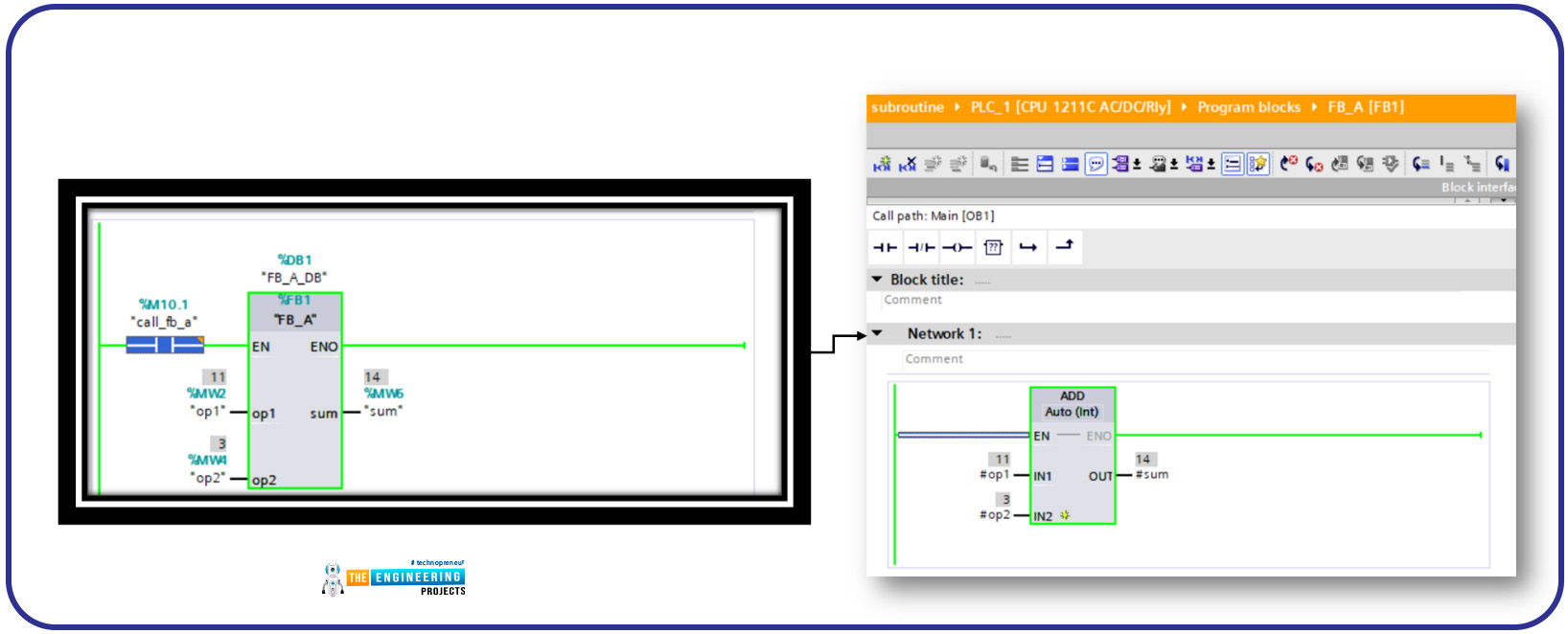
Now let’s check the work with the simulator. Figure 11 shows the results of simulating the calling subroutine based on function FC_A that adds two static operands showing the calling path from the main organization block to the function.
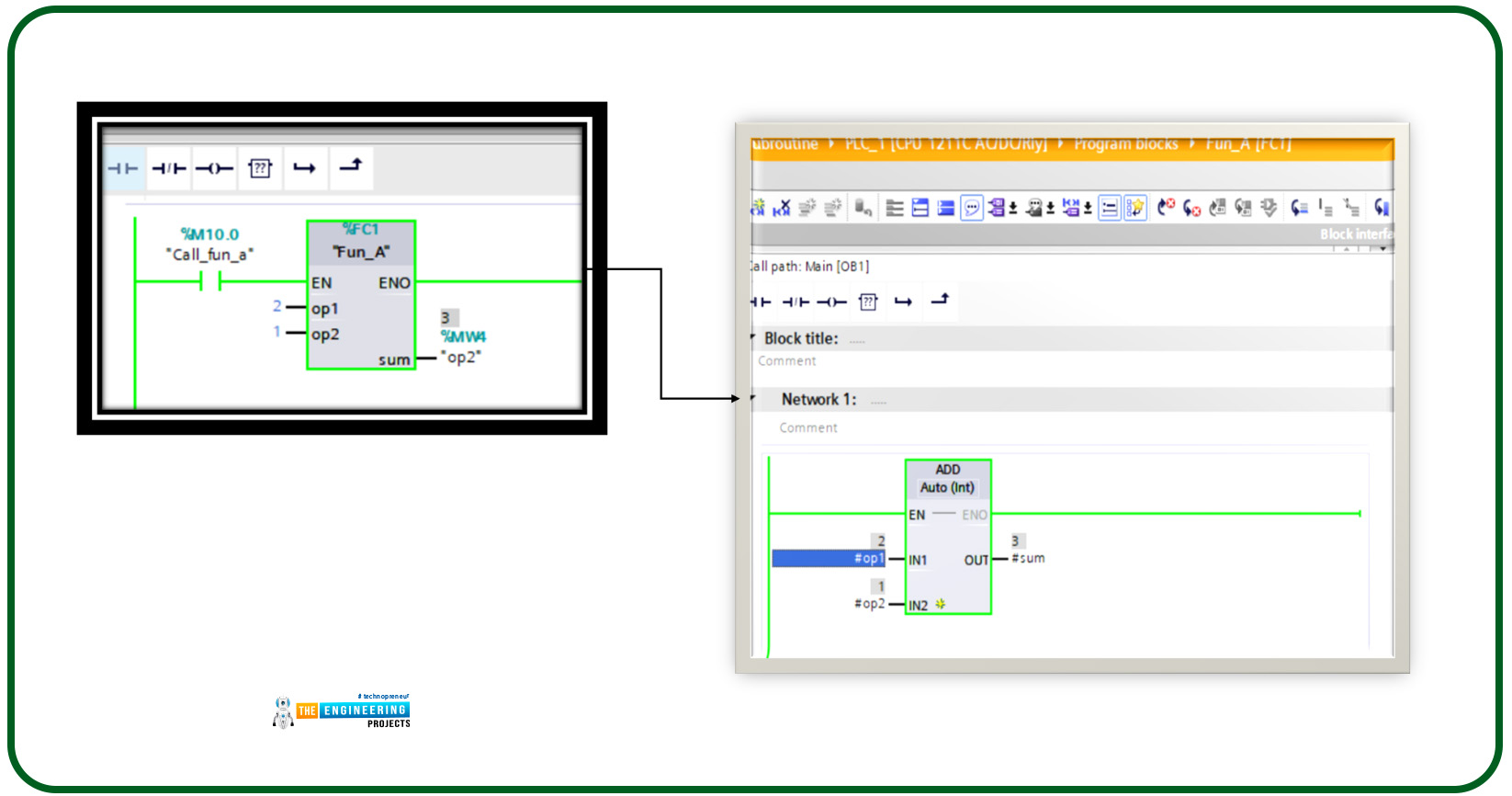
On the other hand, calling a subroutine based on a function block uses an instance of parameters in a data block as shown in fig. 12. This means another instance of data is used every time we called that subroutine while using the function it is referencing the same variables at the same addresses.
What’s next
Thank you guys for following me up to this very point of our tutorial and being very confident by knowing the subroutine you now are all set to write an organized program and readable and reusable piece of code using ladder logic programming. the next time we are going to talk about one of the most important topics in PLC programming which is master reset control showing what is it about and its importance for PLC and control project and for sure will practice with our simulator lab. So be ready and let’s meet in the next tutorial to enjoy learning and practice the PLC ladder programming series.


