Signal and systems is an essential subject in electrical engineering and it is not just limited to this particular branch of engineering but students of many other branches such as computer engineering learn and practice this subject in their field. For design and analysis, all engineering topics make use of models of real-world things. Signals and systems provide you with the ability to take on the challenge of getting the job done.
Signal and system are two terms that, when studied and performed together, form a fantastic visualization of different phenomena. Have a look at these two terms.
What is the signal?
A signal is defined as the description of comparing two parameters and how they vary with each other. Signals are the representation of some sort of information with the help of some visual aid. Signals are usually categorized into two types:
Analog signals
Digital signals
We’ll go through the introduction of both of these one after the other.
Analog Signals
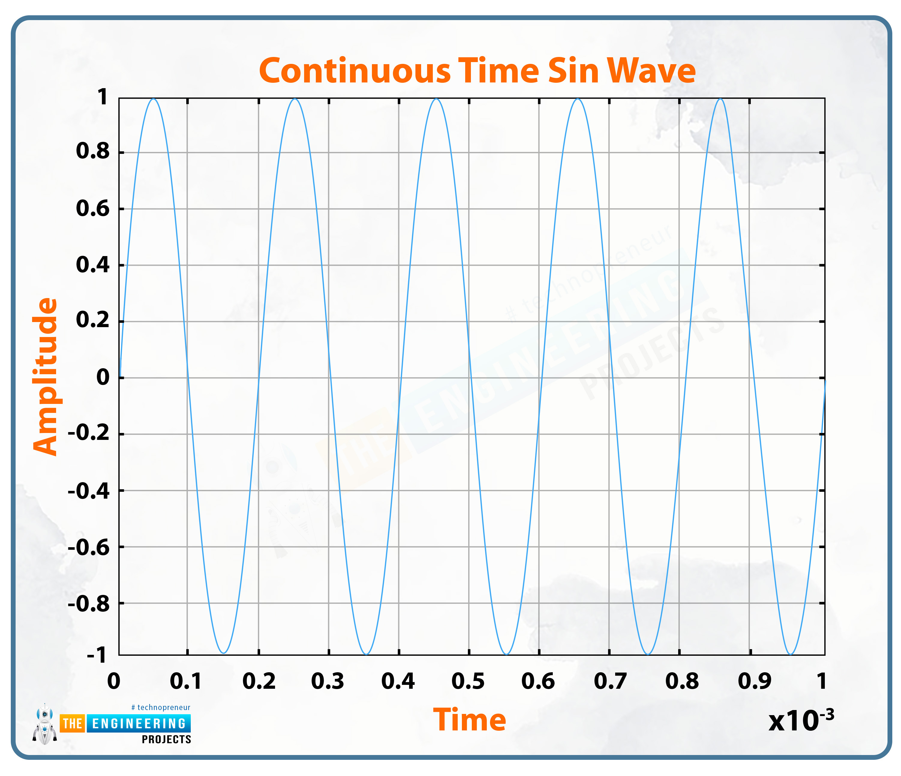
Analog signals are the types of signals that change continuously without any breaks. These signals describe the quantities that have varying values at every point. Therefore, as these signals vary according to time, they are defined over continuous independent variables. Because analog signals have a large amount of information in them, they are comparatively difficult to analyze. At the same time, these signals provide accurate information because the information of every point is stored in them.
Keep in mind, that these infinitely varying signals require infinite memory to store the information of every point on the real line. A sine wave is used to present the analog signal. For a better understanding, we must go through the example of an analog signal.
Example:
One of the most understandable examples of analog signals is speech. When humans (or any other animals) speak, there is the formation of continuous waves in the air due to the pressure we exert on the air through our throats. We all know that pressure is an analog quantity and is the mathematical operation with the independent variable of space and time. Other examples of analog signals are:
Time
Temperature
Distance
Sound
Digital Signals
The word "digital" means discrete, and therefore, digital signals are defined as discontinuous signals. These are less accurate signals because they do not have all the information stored continuously in them. In digital signals, there are only two variables on which the whole system depends. These are 0 and 1. In return, the results are then also represented in the form of these two variables. These are easy to analyze and require a finite amount of memory to store the information.
Example
The Digital Watch is one of the easiest examples through which you can understand the concept of a digital signal. We can have the values of the hours, minutes, and seconds but not have the values in between the seconds. Keep in mind, that there is an infinite number of values even between the seconds that can not be accurately obtained with the help of the digital system.
What is a System?
Any physical collection of components that can both receive and produce a signal is referred to as a system. When speaking in terms of engineering, the input is typically some type of electrical signal X, and the output is typically another electrical signal (the response). Example of System
A system is anything that contains the components that act on the input signal, and after the procedures, the output is obtained on the other end. For example, a system of different procedures is made to remove the noise from the voice. At end A, the voice with the noise is fed into the system, different procedures occur on it and at end B, a pure voice is obtained without noise.
Another example is the system of images in which the pixels of the images are sharpened by using different techniques, and at the output, we get a sharpened image. Other examples of systems are given as:
System of Communication:
A communication system is a system that outlines the process of exchanging information between two different locations.
Control System:
A control system is a system that governs the output to achieve the appropriate reaction. Control systems can also be referred to as command and control systems.
Auditory Processing System
The auditory system in the central nervous system is responsible for converting a diverse range of relatively modest mechanical impulses into a convoluted series of electrical signals.
Signal and Systems as Engineering Subject
The concepts of analog and digital signal processing, which are at the core of contemporary communication and measurement, are discussed in Signals and Systems. In this section, we will discuss the fundamental ideas behind signals with continuous-time and discrete-time in the time and frequency domains. The Fourier transform establishes a connection between time and frequency.
If all of these are confusing at the moment, then do not worry, because we are going to discuss all the concepts used in signals and systems in detail without skipping any points. The good thing is that we’ll be using practical techniques to implement the rules of this subject in different engineering software, mainly MATLAB.
Differences between Digital and Analog signals
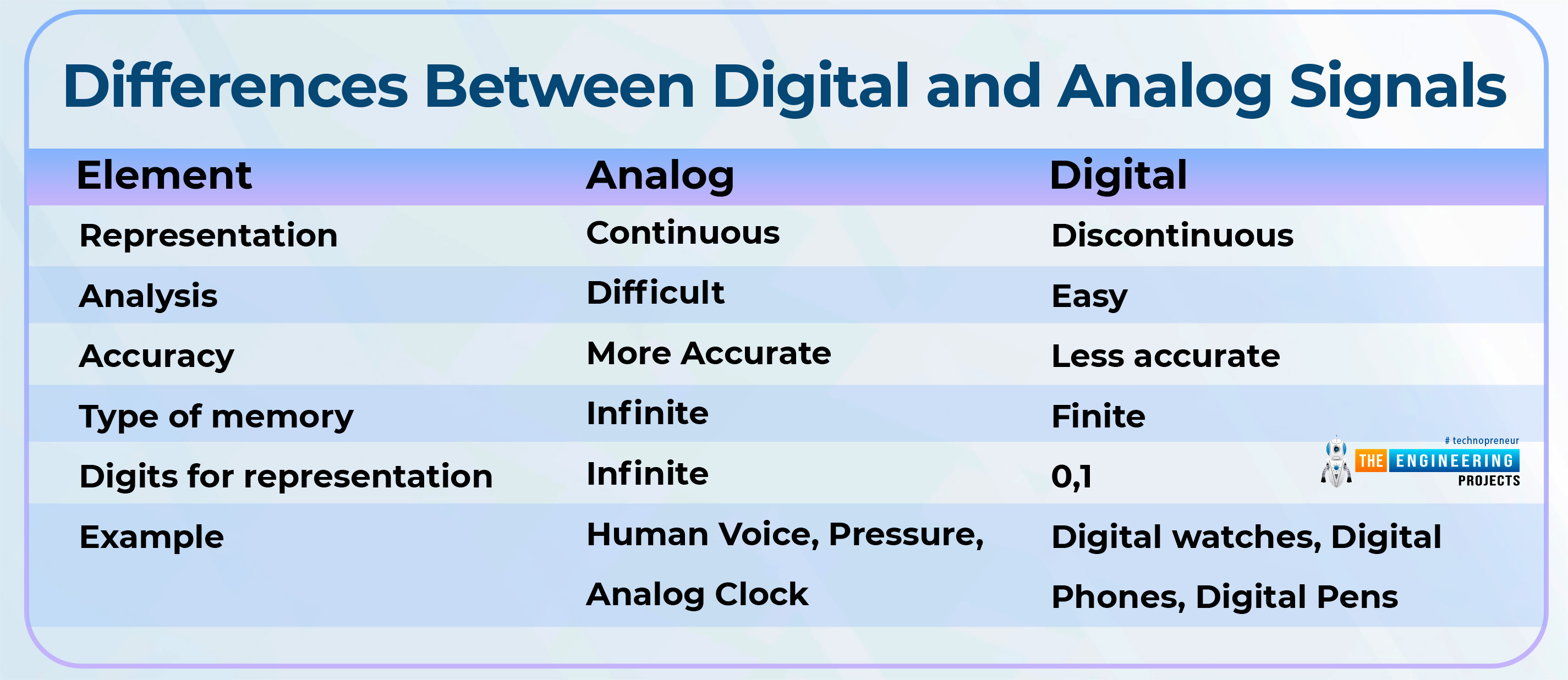
We have read about the types of signals, but here, it is important to discover some important differences between these two types of signals so that you may choose the best one for your experimentation according to the requirements.
Element |
Analog |
Digital |
Representation |
Continuous |
Discontinuous |
Analysis |
Difficult |
Easy |
Accuracy |
More Accurate |
Less accurate |
Type of memory |
Infinite |
Finite |
Digits for representation |
Infinite |
0,1 |
Example |
Human Voice, Pressure, Analog Clock |
Digital watches, Digital phones, Digital pens |
Introduction to MATLAB
MATLAB is a complex calculation software used in many branches of science, especially in the field of engineering, for many purposes. It is made by a company named Mathworks and has fantastic functions and usage that provide a powerful practice medium for engineers. It has numerous applications and is divided into different sections that can be programmed. Basically, MATLAB is a programming language, and for this course, you just have to keep in mind that we’ll define the signals, build the system, provide all the given information, and use different functions on signals to obtain the required results.
We’ll use MATLAB R2016a in this series.
MATLAB language
This is a high-level matrix and array language that supports
Object-oriented programming
Flow control statements
Functions
Data structures
Input/output
and many other languages. It enables "programming in the tiny," which allows for the rapid creation of quick throwaway programs, as well as "programming in the huge," which enables the creation of complete large and complicated application applications.
Prerequisite
Basic knowledge of computer programming.
Basic concepts of variables, constants, expressions, statements, and some others.
Mathworks free account.
System Requirement for MATLAB (Windows)
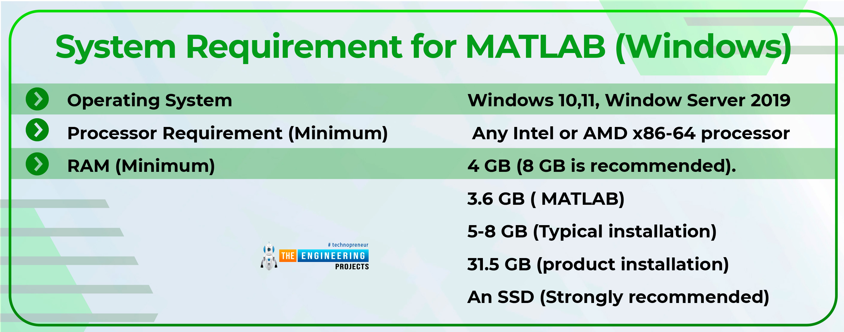
Operating System |
Windows 10,11, Window Server 2019 |
Processor Requirement (Minimum) |
Any Intel or AMD x86-64 processor |
RAM (Minimum) |
4 GB (8 GB is recommended). |
3.6 GB ( MATLAB) 5-8 GB (Typical installation) 31.5 GB (product installation) An SSD (Strongly recommended) |
Creating a Mathworks account is super easy. You just have to provide and confirm your email address and set the password.
Understanding MATLAB Windows
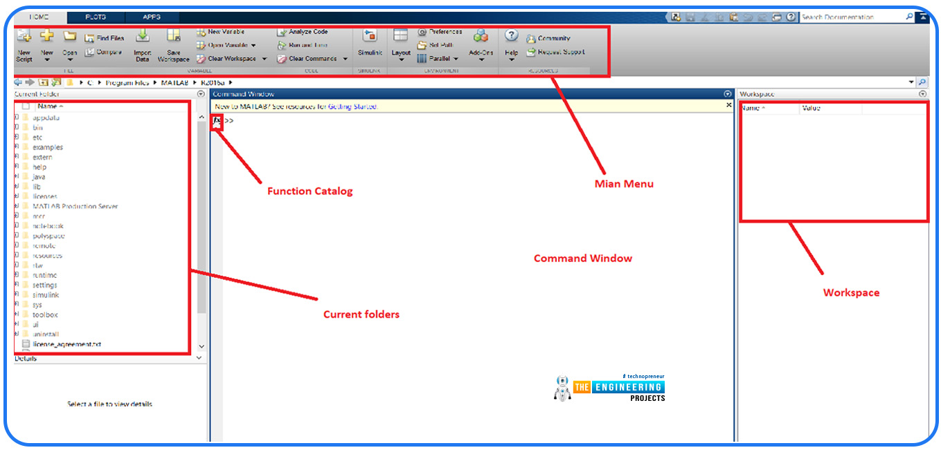
If you are a beginner at MATLAB, then you must know the components of the main screen of MATLAB and the workings of each window. Let’s have a picture of the screen of MATLAB, and all the things will be clear to you in just a bit.

Command Prompt or Window
The command window, which also goes by the name main window, has the job of carrying out the instructions that users type into it.
Current Folders
This is the list of folders that are present in your computer’s specific folders, and for our tutorial, you do not have to know much about it at this stage.
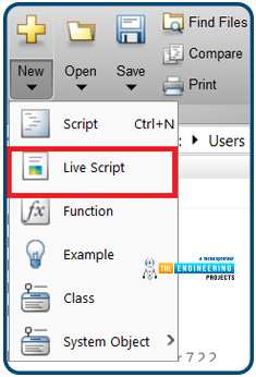
Main Menu
You can pick one of the different functions from this menu, and in this tutorial, you are going to choose the Live Script for the easiest functioning from the drop-down menu.
Workspace
When variables are initiated in the code, the values of each of them are shown in this window.
Function Catalog
This sign indicates the line of the code where you are writing at every step.
Some General Commands of MATLAB
Here, we are discussing some important and simple commands that may or may not be used in every code according to the voice of the user. But for professional users, it is a good practice to use them as they make the result clear.
Grid on
This command creates a grid in the resulting window so that you may have the best idea of the scale of your restaurant signal.
Title
As the name specifies, this creates a title for the result and you have to write the string (which you want in the place of the title) in the single comma notation close to the parentheses just after writing this command.
xlabel
Just like the title, you have to write the string that should appear on the x-axis of your singal by using this command.
ylabel
This command is used to provide a string message on the y-axis.
Signal Formation in MATLAB
Here comes the exciting part. We are going to make simple signals in MATLAB so that all the concepts given above will be clear at once.
Start your MATLAB software.
For best results, it is convenient to work on the live script because, in this way, you are going to check the code at every step and examine the result in the same window.
Analog Signal
Write the code given below on the command window:
A=5;
f=5000;
T=1/f;
t=0:T/100:5*T;
y1=sin(2*pi*f*t);
plot(t,y1)
xlabel('Time')
ylabel('Amplitude')
title('Continuous Time Sine Wave')
grid on
Understanding the code
We have specified the variables A, f, T,t,y1, and the details of each of them is:
A= Amplitude of the sin wave
f=frequency of the wave
T= Specifying that period is inverse of frequency
t = the time of starting, number of steps, and ending of the wave.
y1 = name of the wave in which we have given the formula of the wave that we want to display.
By using all these variables and formulas, we told MATLAB that we wanted a wave of this size to have this specific type of wave.
The plot is the function of plotting the continuous waves. We have specified that we want a wave by using the time on the x-axis and the y1 formula of the wave on the y-axis. In general, the formula is plot(x,y).
Discrete Signals
Right now, just copy and paste this code into your live script and observe the results.
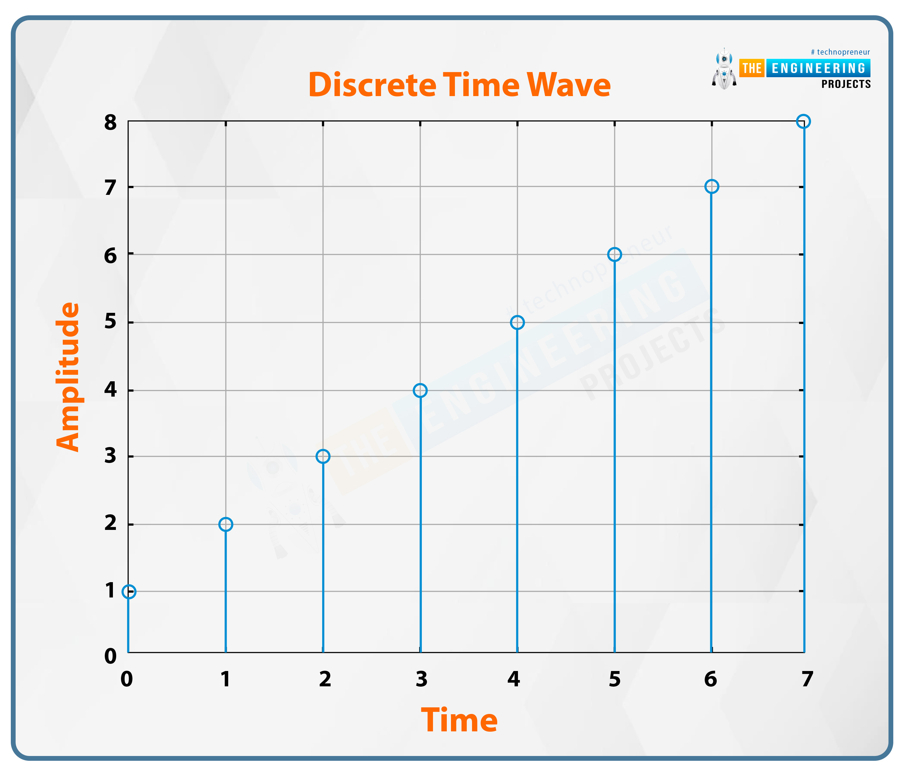
x=[1 2 3 4 5 6 7 8];
n=[0 1 2 3 4 5 6 7];
stem(n,x)
xlabel('Time')
ylabel('Amplitude')
title('Discrete Time Wave')
grid on
Understanding the Code
As mentioned for the analog signals, we have just made two types of waves, where x is the value of the wave at the x-axis and n is the value of the wave at the y-axis. At every step, we have used the function of stem and specified the values where
stem(x,y)
Points to keep in mind:
The number of values on the x-axis must be equal to the number of components on the y-axis.
Analog does not equal continuous, and digital does not equal discrete. On the other hand, in popular usage in the context of digital signal processing, analog systems are typically continuous in time and value, whereas digital systems are typically discrete in both time and value. Therefore, there is some improper use of the language.


