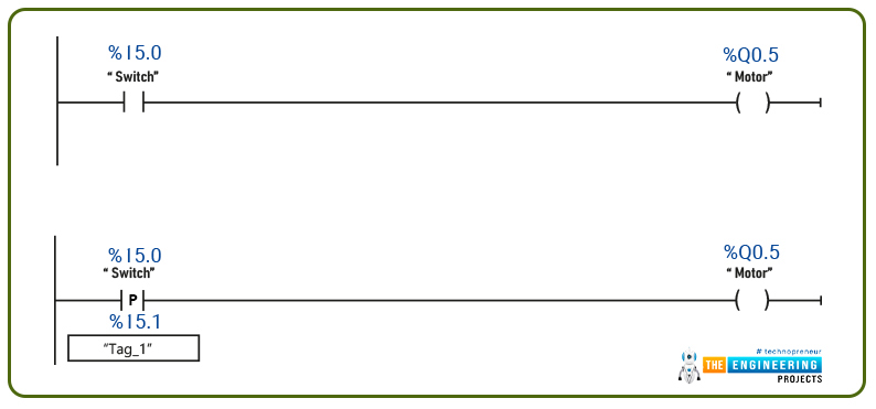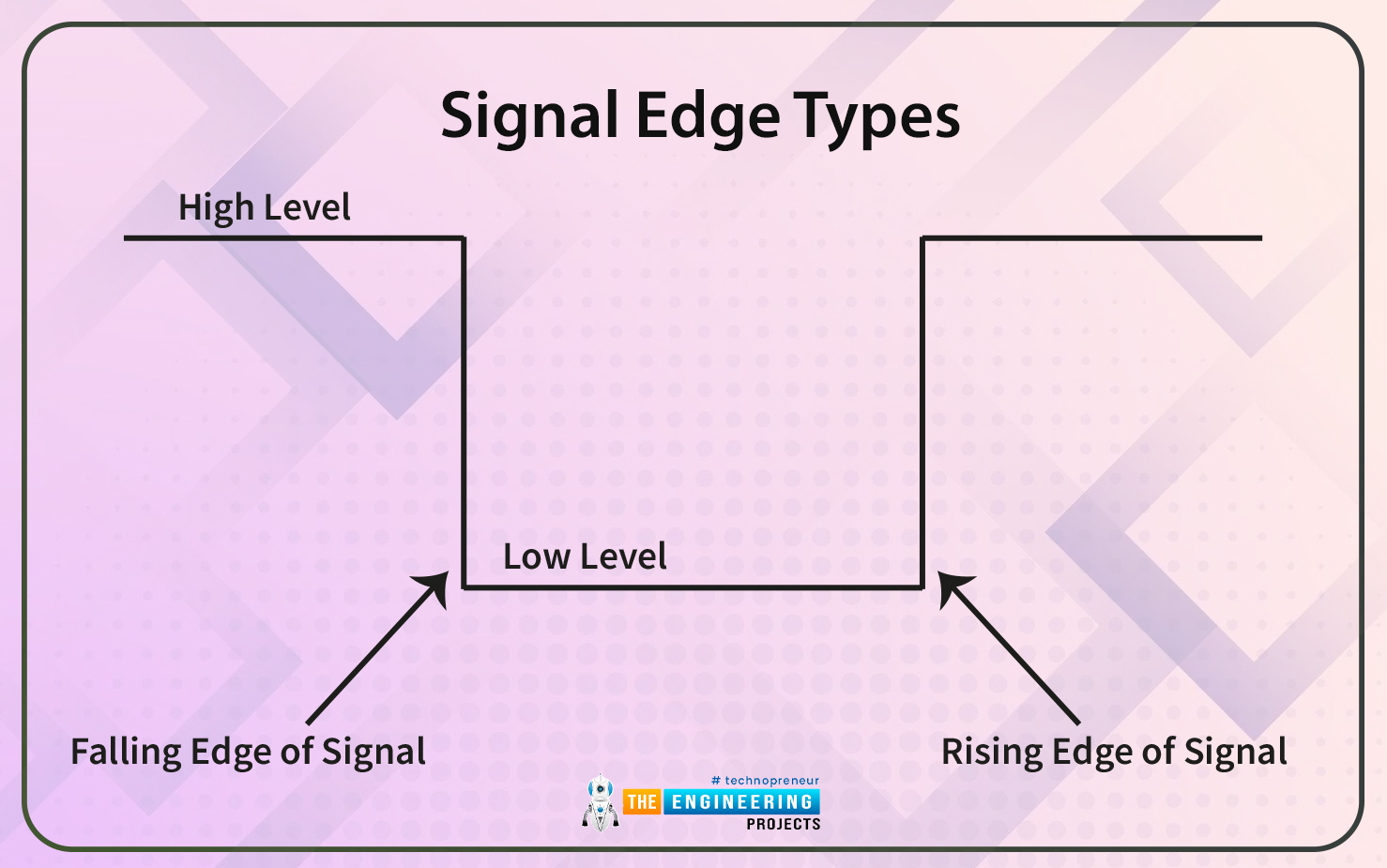
Signal Edge Types
There are two edge types:
- Falling edge.
- Rising edge.

Rising Edge in PLC Ladder Logic
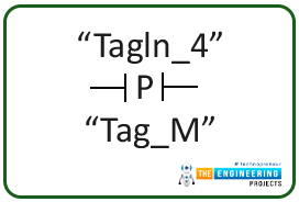
Figure 3 shows the general symbol of a rising edge. The letter “P” denotes a positive edge. while fig. 4. Depicts the rising edge in ladder logic in the TIA portal of siemens software.

In ladder programming, the rising edge shows a positive rising edge received for the signals. In fig. 4, the rising edge is for the signal tagged as “TagIn_4” and the previously saved value is stored in “Tag_M”. the system can recognize a rising edge by comparing the buffered value stored in “Tag_M” and the current value in “TagIn_4”. For example, if the previous value stored in “Tag_M” is False, and the current value in “TagIn_4” shows high logic, this would mean a rising edge is received.
Falling edge in PLC ladder
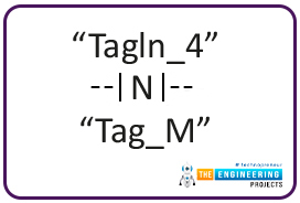
Figure 5 shows the general symbol of a falling edge. The letter “N” denotes a negative edge. while fig. 6. Depicts the falling edge in ladder logic in the TIA portal of siemens software.

In ladder programming, the rising edge shows a negative or falling edge received for the signals. In fig. 6, the falling edge is for the signal tagged as “TagIn_4” and the previously saved value is stored in “Tag_M”. the system can recognize a falling edge by comparing the buffered value stored in “Tag_M” and the current value in “TagIn_4”. For example, if the previous value stored in “Tag_M” is True, and the current value in “TagIn_4” shows low or false logic, this would mean a falling edge is received.
Set Output on a Positive Edge
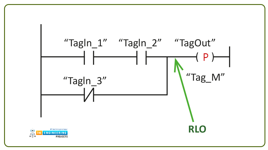
Now let’s do the same concept on the output side, fig. 7 shows the set output ladder instruction on a rising or positive edge. In this instruction, the result of the logic operation (RLO) which represents the left part before the output is evaluated to check the transition in its state. If the RLO changes from false to true then the output will be set for one scan cycle.

Figure 8 shows an example of the set output on a positive edge. On the most left, the coil with the letter “P” inside represents the instruction. The instruction works by saving the previous value of RLO into “Tag_M” and verifying the changes in a state with “TagOut”. For example, if the “Tag_M” holds a true state while the previously stored value in “Tag_M” was false. That would show a positive edge and the output will be set to true for the complete scan cycle.
Set Output on a Negative Edge
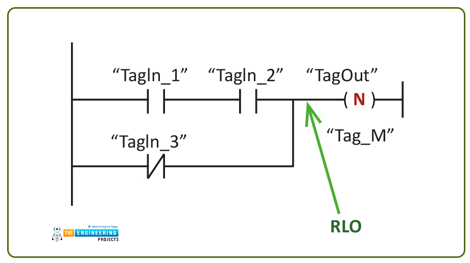
Figure 9 shows the set output ladder instruction on a falling or negative edge. In this instruction, the result of the logic operation (RLO) which represents the left part before the output is evaluated to check the transition in its state. If the RLO changes from true to false then the output will be set for one scan cycle based on detecting a falling edge of RLO.

Figure 10 shows an example of the set output on a falling or negative edge. On the most left, the coil with the letter “N” inside represents the instruction. The instruction works by saving the previous value of RLO into “Tag_M” and verifying the changes in a state with “TagOut”. For example, if the “Tag_M” holds a false state while the previously stored value in “Tag_M” was true. That would show a negative or falling edge of the RLO. Consequently, the output will be set to true for the complete scan cycle.
Simulating edge detection
Now let’s go to our lab and open a simulator to enjoy practicing very critical points in ladder logic programming. Yes, my friends, these are very critical points and are used smartly in solving very hard problems to solve. But, by comprehensive these points, you will be superb in your field as a prospective ladder logic programmer. Two points we are going to simulate, the first one is the ringing and falling edge of the inputs and their effects on activating and energizing the output for a complete pulse. And the rising and falling edge cases of the result of logic output (RLO) and its effects on energizing the output for a complete pulse.
Simulating rising edge
Now, let’s assume we have a situation in the factory that, when specific action occurred, the output will be energized. In the example represented by fig. 11, when and only when input A, turned on, we need to start the output. That means the only scenario in which the output is turned on is when input A state changed from false to true. So let us simulate three scenarios, the first one shown in fig. 11, in this scenario the input previous status is saved in input B, while the current or new state is saved in input A. notice when the input does not change and it is false, the output is turned off.

Now let’s turn on input A, so now input changed from false to true as shown in Fig. 12. Ohh, notice the output comes true and that’s the rising edge at when the input changes from false to true.

And in the last scenario, when the input keeps true meaning the previous status was true and the current state is true, then the output is false as shown in Fig. 13.

In a conclusion, in rising edge, the output only gets true when the input changed from false to true.
Falling Edge in PLC Simulator
Now, let’s assume we have another situation in the factory that, when an input or sensor turns off or changed from true to false, the output will be energized. In the example represented by fig. 14, when and only when input A, turned out from ON to off, the output will be energized. That means the only scenario in which the output is turned on is when input A state changed from true to false. So let us simulate three scenarios, the first one shown in fig. 14, in this scenario the input previous status is saved in input B, while the current or new state is saved in input A. notice when the input does not change and it is false, the output is turned off.

Now let’s turn on input A, so now input changed from false to true as shown in Fig. 15. Ohh, notice the output is false because that’s not a falling edge as the input changes from false to true.

And in the last scenario, when the input changed from true to false which is a falling edge. Therefore, the output turned on as in fig. 16.

In a conclusion, in a falling edge, the output only gets true when the input changed from true to false.
Simulating set output on the rising edge
Now, my friends, we need to run the output for one pulse based on the result of logic output (RLO). Figure 17 shows the scenario of having a false state of the RLO, the output is false because there is no falling edge detected for the RLO.
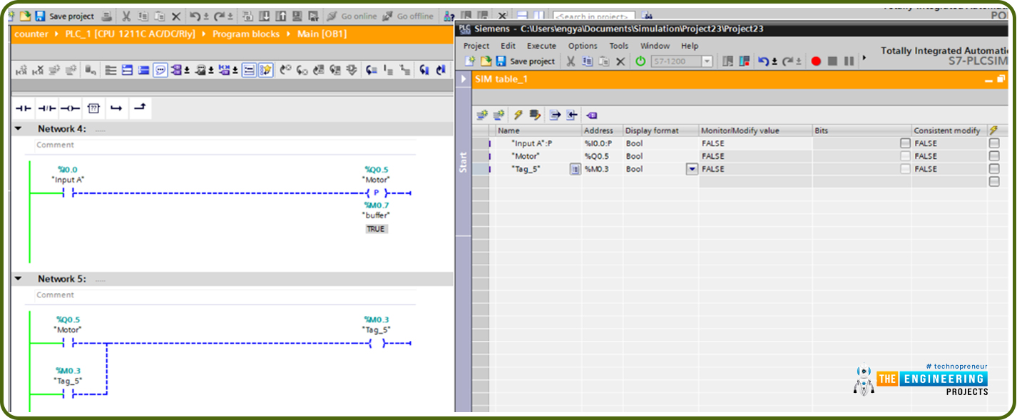
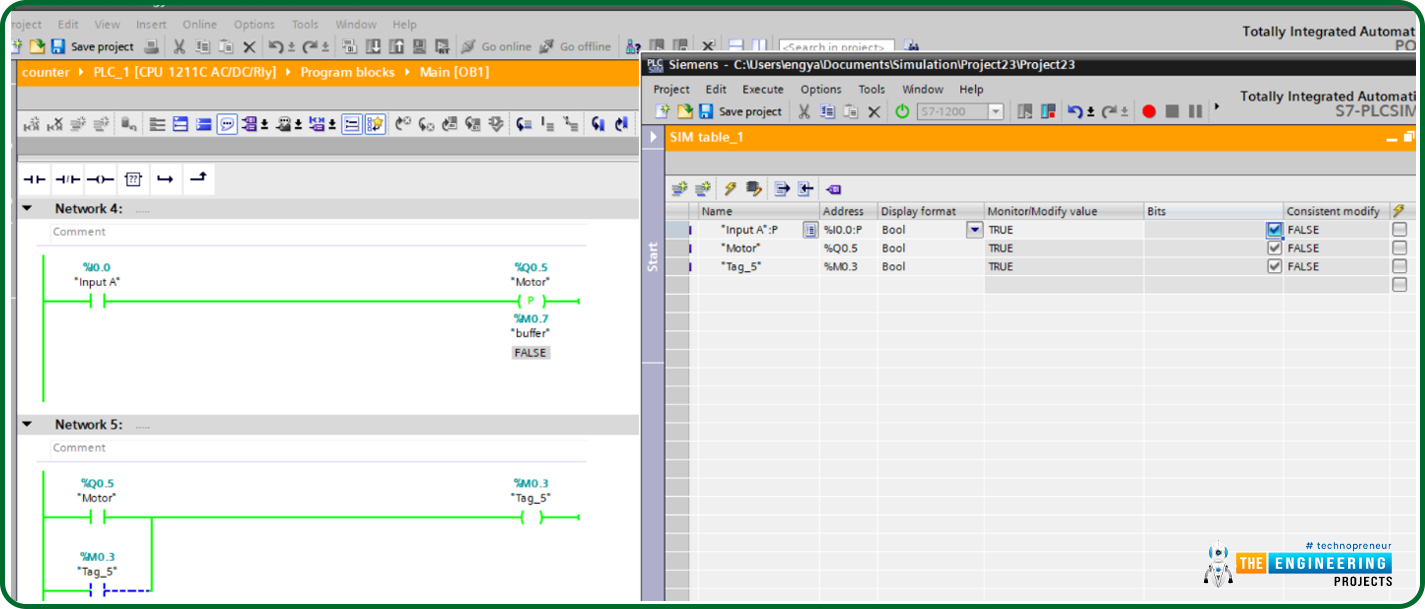
Figure 18 shows the case when the RLO is turned from false to true, the output comes true but for one pulse notice the previous status represented by buffer has become false but the output after pulse time returns to false. However, the pulse of the output has been detected thanks to energizing output tag_5.
Simulating set output on falling edge
Figure 19 shows the very initial case of set output with a falling edge. To show, the case of the falling edge of RLO, we use another rung that would energize another output at Q0.6 when and only when the falling edge of the RLO occurs. In Fig. 19, the RLO was false. Therefore, there is no cause for a falling edge when RLO changed from true to false. So the output shows a false state.
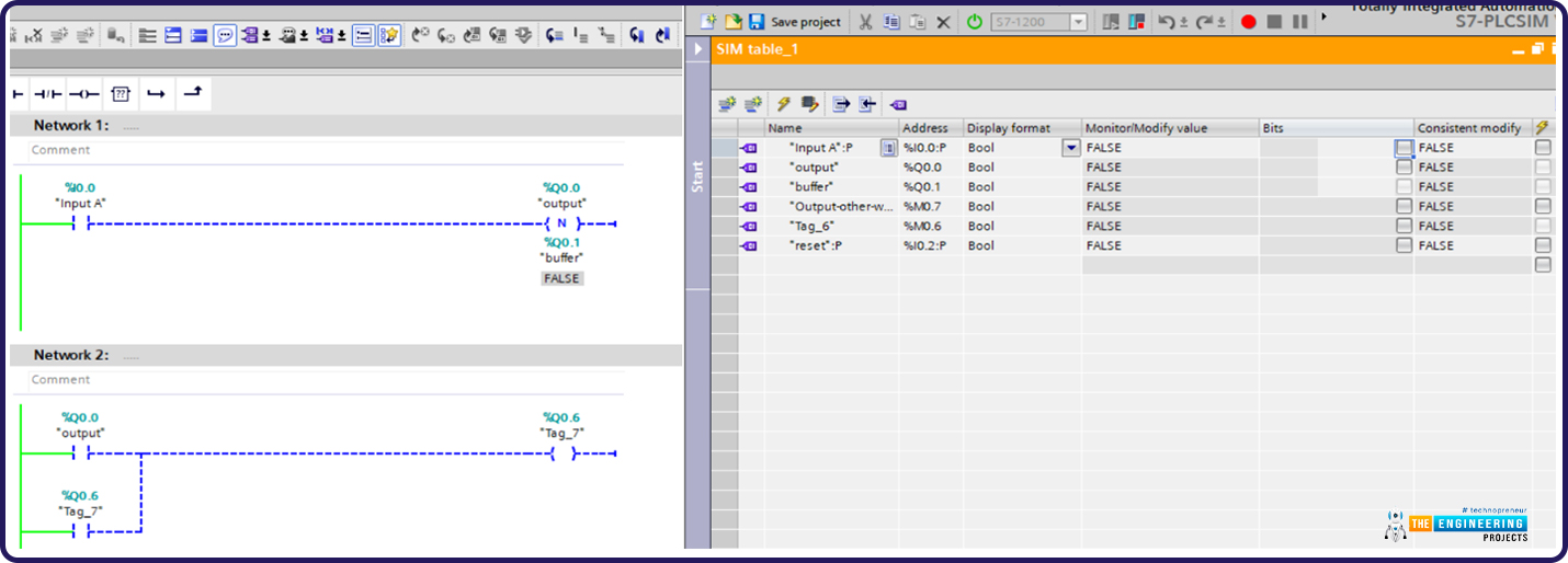
Now let’s turn on the RLO, so the RLO changed from false to true which is still not a case of a falling edge of the RLO. SO the output is still false as shown in Fig. 20 represented by output Q0.6.
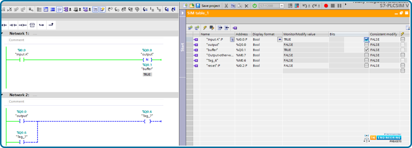
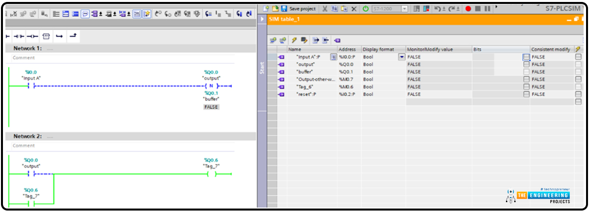
Figure .21 shows the scenario of the RLO turning from true to false which is a falling edge. In that case, the output will be turned on for one pulse and as a result, latching output at Q0.6 as shown in rung 2 of fig. 21.
What’s Next
Once more I would like to thank all my friends for continuing with our learning and practicing our PLC ladder logic series. Now we have learned the concept of edge detection, its importance, and how we can utilize the rising and following edge in some critical and accurate cases of logic. The rising and falling edge of the inputs can energize an output in a pulsative way or for only one pulse. This scenario exists in the industry and is very common. For example, when you want to energize a safety device by the occurrence of some conditions like increase of liquid level or temperature or pressure et cetera. Also, the result of logic output (RLO), can be used to set or reset output for one pulse. In the next tutorial, we are going to introduce the latching in more detail showing why we need to latch an output, the ways of latching with examples, and for sure enjoying our practicing with the PLC ladder logic simulator.


