
ESP32 Low Power Modes


Hello readers, hope you all are doing great. In this tutorial, we will discuss low power modes in ESP32, their purpose and their implementation to increase the battery life by reducing power consumption.
Purpose of Low Power Modes

Fig.1
Along with multiple wireless and processing features, ESP32 also provides us with a power-saving feature by offering sleep modes. When you are powering the ESP32 module from the live supply using an adaptor or a USB cable, there is nothing to worry about power consumption. But when you are using a battery, as a power source to ESP32, you need to manage the power consumption for longer battery life.
Low Power Modes in ESP32
When ESP32 is in sleep mode, a small amount of power is required to maintain the state of ESP32 in RAM (random access memory) and retain necessary data. Meanwhile, the power supply won’t be consumed by any unnecessary peripheral or inbuilt modules like Wi-Fi and Bluetooth.
ESP32 offers 5 power modes. Each mode is configurable and offers different power-saving capabilities:
- Active Mode
- Modem Sleep Mode
- Light Sleep Mode
- Deep Sleep Mode
- Hibernation Mode

Fig. 2
Active Mode:
- In active mode, all the modules and features of ESP32, like processing cores, Wi-Fi, Bluetooth, radio etc. remain active all the time.
- Most of the power consumption occurs in this power mode which can vary between 160 -240mA and sometimes the maximum consumption could reach up to 790mA (when both Wi-Fi and Bluetooth are enabled or active at the same time).
Modem Sleep Mode:
- In this mode, radio, Wi-Fi, Bluetooth will be disabled and everything else will remain active. Power consumption in this mode varies from 3 to 20mA.
- Sleep modes can switch between modem and active modes as per the predefined intervals, by following the associated sleep pattern.
Light Sleep Mode:
- During this mode, the central processing unit is paused by turning/powering off its clock.
- ULP- coprocessor and RTC (real-time clock) remain active during light sleep mode and power consumption is 0.8mA.
Deep Sleep mode:
- In this mode, the Ultra Low Power (ULP) coprocessor remains active while the ESP32 core and other digital peripherals remain inactive.
- The ULP coprocessor wakes up the core processor when required.
- The amount of power consumed in this mode is 10uA.

Fig 3
Hibernation Mode:
-
- In this mode, the ULP coprocessor and internal oscillator both are disabled.
- Only a real-time clock (RTC) remains active to wake up the processor and other required modules from hibernation mode and the power consumption in this mode is extremely low that is approximately 2.5uA.
For a better understanding of low power modes in ESP32, we are going to implement deep sleep mode in esp32 and will also discuss how to wake up the device from deep sleep mode.
Deep Sleep mode and Wakeup Using Capacitive Touch-sensitive pins
To implement deep sleep modes we are going to use another ESP32 feature that is Capacitive Touch Sensing pins. These pins can sense the presence of a body that holds an electric charge.
So we are going to use these touch-sensitive pins for waking up ESP32 from deep sleep mode using the Arduino IDE compiler.
In Arduino IDE examples are given for deep sleep mode with various wake-up methods.
- Follow the image attached below to open the example code:
-
Arduino IDE Code
#define Threshold 40 /* Greater the value, more the sensitivity */ RTC_DATA_ATTR int bootCount = 0; touch_pad_t touchPin; /* Method to print the reason by which ESP32 has been awaken from sleep */ void print_wakeup_reason(){ esp_sleep_wakeup_cause_t wakeup_reason; wakeup_reason = esp_sleep_get_wakeup_cause(); switch(wakeup_reason) { case ESP_SLEEP_WAKEUP_EXT0 : Serial.println("Wakeup caused by external signal using RTC_IO"); break; case ESP_SLEEP_WAKEUP_EXT1 : Serial.println("Wakeup caused by external signal using RTC_CNTL"); break; case ESP_SLEEP_WAKEUP_TIMER : Serial.println("Wakeup caused by timer"); break; case ESP_SLEEP_WAKEUP_TOUCHPAD : Serial.println("Wakeup caused by touchpad"); break; case ESP_SLEEP_WAKEUP_ULP : Serial.println("Wakeup caused by ULP program"); break; default : Serial.printf("Wakeup was not caused by deep sleep: %d\n",wakeup_reason); break; } } /* Method to print the touchpad by which ESP32 has been awaken from sleep */ void print_wakeup_touchpad(){ touchPin = esp_sleep_get_touchpad_wakeup_status(); switch(touchPin) { case 0 : Serial.println("Touch detected on GPIO 4"); break; case 1 : Serial.println("Touch detected on GPIO 0"); break; case 2 : Serial.println("Touch detected on GPIO 2"); break; case 3 : Serial.println("Touch detected on GPIO 15"); break; case 4 : Serial.println("Touch detected on GPIO 13"); break; case 5 : Serial.println("Touch detected on GPIO 12"); break; case 6 : Serial.println("Touch detected on GPIO 14"); break; case 7 : Serial.println("Touch detected on GPIO 27"); break; case 8 : Serial.println("Touch detected on GPIO 33"); break; case 9 : Serial.println("Touch detected on GPIO 32"); break; default : Serial.println("Wakeup not by touchpad"); break; } } void callback(){ //placeholder callback function } void setup(){ Serial.begin(115200); delay(1000); //Take some time to open up the Serial Monitor //Increment boot number and print it every reboot ++bootCount; Serial.println("Boot number: " + String(bootCount)); //Print the wakeup reason for ESP32 and touchpad too print_wakeup_reason(); print_wakeup_touchpad(); //Setup interrupt on Touch Pad 3 (GPIO15) touchAttachInterrupt(T3, callback, Threshold); //Configure Touchpad as wakeup source esp_sleep_enable_touchpad_wakeup(); //Go to sleep now Serial.println("Going to sleep now"); esp_deep_sleep_start(); Serial.println("This will never be printed"); } void loop(){ //This will never be reached }
Code Description
- The first step is to set the threshold value for touch-sensitive pins.
- When a body, containing an electric charge touches a touch-sensitive pin, the threshold value decreases below 40, that decrease in the threshold value will make ESP32 wake up from deep sleep mode. In the example code threshold value is 40.
- The next task is to store the data into RTC memory (using RTC_DATA_ATTR ) because in deep sleep mode only RTC remains active and all other peripherals, processors, wireless modules will be disabled.
- ESP32 offers 8kB SRAM on RTC to store the data.
- But when you press EN/reset button the data stored in RTC memory will also be erased.
- bootCount an integer type variable is used to count the number of times ESP32 has woken up during sleep mode. The value of bootCount variable is stored in RTC memory.

- The print_wakeup_reason() function is used to print the reason for ESP32 wakeup from deep sleep whether it is due to an external interrupt, timer, or touch-sensitive pins.
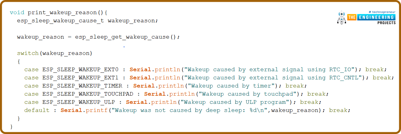
- The ESP32 has multiple capacitive touch-sensitive GPIO pins which can be used to wake up esp32 from deep sleep mode.
- Print_wakeup_touchpad() function is used to print the GPIO pin which made ESP32 wake up from sleep mode.
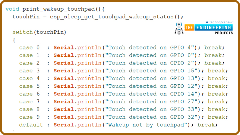
- When you hold a capacitive sensitive pin for a longer duration the threshold value (initialized globally) decreases from its predefines value i.e., 40 which will cause ESP32 to wake up, at that time the callback() function comes into action.
- This function will be used as an argument inside the touchAttachInterrupt() function.

Setup()
- Inside the setup() function the first task is to start the serial monitor with a baud rate of 115200.
- Next, if there is any increment in boot count due to wake up calls, then print that count on the serial monitor.
- Print_wakeup_reason() is used to print whether the ESP32 wake-up is caused by an external interrupt, timer or a capacitive sensitive pin.
- If the wake up is due to a capacitive sensitive pin then the print_wakeup_touchpad() function will print the GPIO pin number which caused the wake-up.
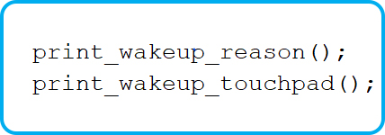
- The next task is to attach the interrupt using touchAttachInterrupt() function, to capacitive sensitive GPIO pin which you will use to wake up ESP32.
- In this example we are using GPIO 15 capacitive sensitive pin as a wakeup interrupt pin.
- esp_sleep_enable_touchpad_wakeup() is used to enable touch sensor feature.

- esp_deep_sleep_start() function is used to make ESP32 enter to deep sleep mode.
- Once ESP32 enters the sleep mode no other operation or data communication is possible until it receives a wakeup call.
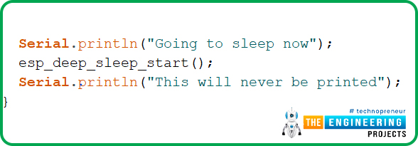
Fig 12
Loop()
- In this example code, there is nothing, written inside the loop function. But you can change the code as per your requirements.
Code Testing
- To test the code, use a connecting wire (male to female) and connect one side to ESP32’s touch-sensitive pin (which you have mentioned in the code as an interrupt).
- When you touch that pin an interrupt will be generated to wake ESP32 from sleep.
- You can see the results on a serial monitor or can check the current consumption or can run other functions once it is awake like blinking LED.
- In this code, we are using GPIO_15 touch-sensitive pin.
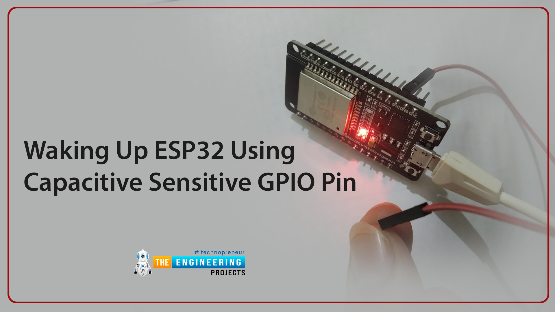
Fig. 13 waking up esp32 using capacitive sensitive GPIO pin
We have attached a screenshot from the serial monitor for reference.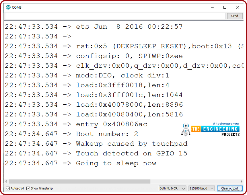
Fig. 14
Deep Sleep mode and Wakeup Using Interrupt method
Arduino IDE Code
#define uS_TO_S_FACTOR 1000000ULL /* Conversion factor for micro seconds to seconds */ #define TIME_TO_SLEEP 5 /* Time ESP32 will go to sleep (in seconds) */ RTC_DATA_ATTR int bootCount = 0; /* Method to print the reason by which ESP32 has been awaken from sleep */ void print_wakeup_reason(){ esp_sleep_wakeup_cause_t wakeup_reason; wakeup_reason = esp_sleep_get_wakeup_cause(); switch(wakeup_reason) { case ESP_SLEEP_WAKEUP_EXT0 : Serial.println("Wakeup caused by external signal using RTC_IO"); break; case ESP_SLEEP_WAKEUP_EXT1 : Serial.println("Wakeup caused by external signal using RTC_CNTL"); break; case ESP_SLEEP_WAKEUP_TIMER : Serial.println("Wakeup caused by timer"); break; case ESP_SLEEP_WAKEUP_TOUCHPAD : Serial.println("Wakeup caused by touchpad"); break; case ESP_SLEEP_WAKEUP_ULP : Serial.println("Wakeup caused by ULP program"); break; default : Serial.printf("Wakeup was not caused by deep sleep: %d\n",wakeup_reason); break; } } void setup(){ Serial.begin(115200); delay(1000); //Take some time to open up the Serial Monitor //Increment boot number and print it every reboot ++bootCount; Serial.println("Boot number: " + String(bootCount)); //Print the wakeup reason for ESP32 print_wakeup_reason(); /* First we configure the wake up source We set our ESP32 to wake up every 5 seconds */ esp_sleep_enable_timer_wakeup(TIME_TO_SLEEP * uS_TO_S_FACTOR); Serial.println("Setup ESP32 to sleep for every " + String(TIME_TO_SLEEP) + " Seconds"); /* Next we decide what all peripherals to shut down/keep on By default, ESP32 will automatically power down the peripherals not needed by the wakeup source, but if you want to be a poweruser this is for you. Read in detail at the API docs http://esp-idf.readthedocs.io/en/latest/api-reference/system/deep_sleep.html Left the line commented as an example of how to configure peripherals. The line below turns off all RTC peripherals in deep sleep. */ //esp_deep_sleep_pd_config(ESP_PD_DOMAIN_RTC_PERIPH, ESP_PD_OPTION_OFF); //Serial.println("Configured all RTC Peripherals to be powered down in sleep"); /* Now that we have setup a wake cause and if needed setup the peripherals state in deep sleep, we can now start going to deep sleep. In the case that no wake up sources were provided but deep sleep was started, it will sleep forever unless hardware reset occurs. */ Serial.println("Going to sleep now"); Serial.flush(); esp_deep_sleep_start(); Serial.println("This will never be printed"); } void loop(){ //This is not going to be called }
Code Description
- The first task is, to define the timer period for which ESP32 will be in deep sleep mode.
- As we know that ESP32 operates at the MHz frequency range so the timer will be in microseconds. So, it is required to convert the time into seconds.
- To add a timer of 5sec we need to multiply 5*1000000.
- bootCount an integer type variable is used to count the number of times ESP32 has woken up during sleep mode. The value of bootCount variable is stored in RTC memory.
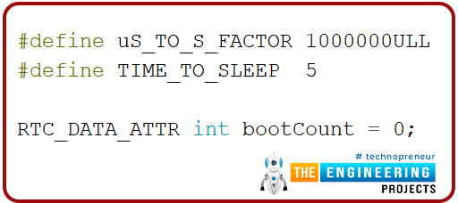
Fig 15
- The print_wakeup_reason() function is used to print the reason for ESP32 wakeup from deep sleep whether it is due to an external interrupt, timer or touch-sensitive pins.
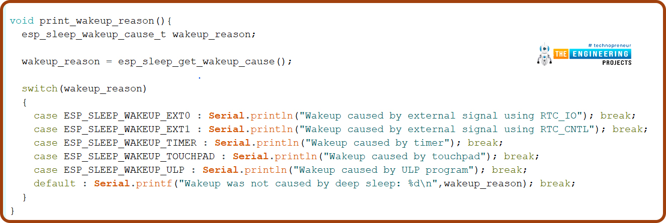
Fig. 16
Setup()
- As discussed earlier, inside the setup function first we need to initialize the serial monitor at 115200 baud rate and then print the value of bootCount variable which is incrementing every time a wakeup interrupt occurs.

Fig. 17
- The esp_sleep_enable_wakeup() function is used to enable the timer to generate a timer interrupt by passing time in microsecond as an argument.
- In the beginning of code we have defined some global variable to add 5 sec timer (or 5000000us) and after every 5 sec ESP32 should wake up from deep sleep till 5 sec.

Fig. 18
- esp_deep_sleep_start() function is used to make ESP32 enter the deep sleep mode.
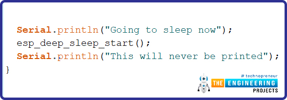
Fig. 19
Testing
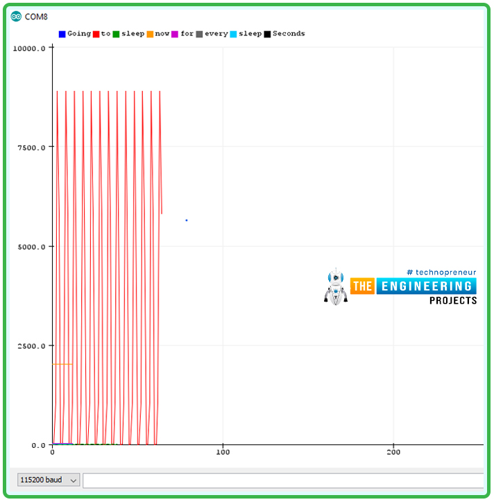
- You can see the results of above code on serial monitor as shown is the image attached below.
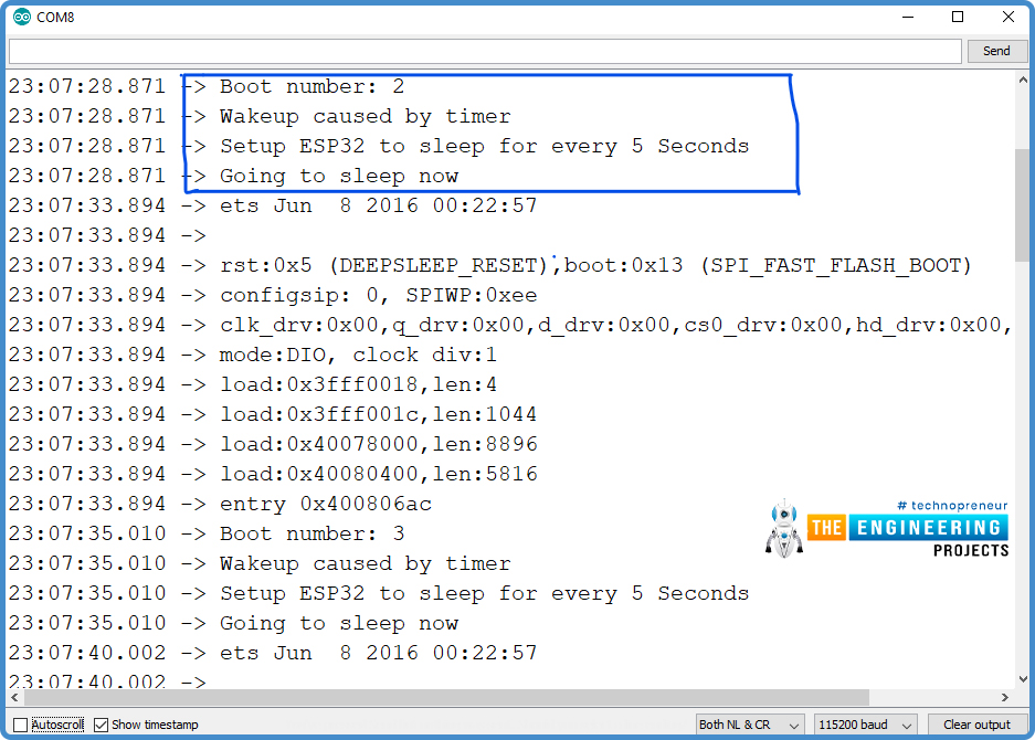
Fig 20
This concludes the tutorial. I hope you found this useful, and I hope to see you soon for the new ESP32 tutorial.


 1 user


 Continue Wishlist


 Getting Started Guide
 Help Center
 Contact us
 Doist Blog
 Privacy
 Security
 Terms of Service
 What's new: Channel Descriptions


 ESP32 Projects
 zoyebella
 0 Comments


 2.3k
2.3k
 953
953
 921
921
 2.1K
2.1K


 Purpose of low power modes
Low power modes in ESP32
Active mode
Modem sleep mode
Light sleep mode
Deep sleep mode
Hibernation mode
Implementation of deep sleep mode and wakeup using capacitive touch sensitive pins
Arduino IDE code
Implementation of deep sleep mode and wakeup using interrupt method
Code description
 Sunday, December 12, 2021