| Where To Buy? | ||||
|---|---|---|---|---|
| No. | Components | Distributor | Link To Buy | |
| 1 | LEDs | Amazon | Buy Now | |
| 2 | Arduino Mega 2560 | Amazon | Buy Now | |
4-Way Traffic Light Control using Arduino:
Traffic lights are an integral part of the world’s transportation systems. Over the years a number of different algorithms regarding traffic lights have been developed. The algorithm being used at any place for the purpose of controlling traffic takes into account of various factors, such as number of lanes, people that cross a certain road, etc. The most common usage of traffic lights is to control the flow of traffic, which means providing a steady flow for people to go about their daily business on the road. Traffic lights help reduce accidents by a large margin since they allow the flow of vehicles in only one direction at a time. Traffic lights also help in avoiding traffic jams. The most common traffic light pattern being used in the world today is a 4-way traffic control that accounts for pedestrians as well. This sort of pattern is used in main city blocks and squares since these possess both vehicular traffic as well as pedestrian traffic. Traffic lights have a universal color understanding that red light signals for the traffic to stop, yellow light serves as a transition light from going to stop and vice versa.
Software to Install:
Since we are simulating this project instead of designing it using hardware components, you need to fill some requisites so that you can follow our procedure. At first, we need to have the simulating software. For simulation purposes, we will use the Proteus software, if you already have that installed, that is excellent. However, if you don’t, you should Install Proteus Software. Proteus is a circuit simulating software that has an open database that can be customized quite easily, leaving room to add new components along with their libraries. To start working with Proteus for this project, you need to add the following libraries:
- Arduino Library for Proteus: This library includes all the Arduino boards, giving you options to simulate your circuit exactly according to your needs.
Project Overview:
The main components of a 4-way traffic light are:
- Arduino Mega: For this circuit, we recommend using Arduino mega, that is because to control 4-way traffic along with pedestrian lights, we need 20 output pins while an Arduino UNO only has 14 digital I/O pins.
- Traffic light module: This is an inbuilt traffic light module you can find in Proteus, there is no need for any additional libraries for this.
- Pedestrian Lights: To distinguish pedestrian lights, we will use simple LEDs.
In this certain design, we have used delays to control the ON and OFF time of the traffic lights. There are other ways around this as well but using delays with Arduino is the simplest and most effective way for small projects.
The pedestrian lights are set up so that whenever a certain traffic light is GREEN, its opposing pedestrian light on which there is no traffic is turned ON and signals for the pedestrians to walk.
Components Needed:
- Arduino Mega
- Green and Red LEDs
- Traffic Lights
Component details:
Arduino Mega:
Arduino Mega is a programmable microcontroller board.
Arduino Mega contains ATMegaGA2560 and is based on that microcontroller.
Every Arduino board is equipped with voltage regulators to make sure an excessive input does not burn components on the board.
Arduino Mega has 53 digital I/O pins.
Traffic Lights:
This module consists of three lights, namely, Red, Yellow and Green.
All three lights have separate input pins through which each light is controlled independently.
Make sure you connect all three pins to the Arduino, even if you are not using a certain light. This is because Proteus simulation only works when all the pins of traffic light are connected.

Figure 2: Traffic Lights
Proteus Simulation of Traffic Light Control:
We will first make the circuit on our Proteus software, after doing the connections of the circuit, we will work on the Arduino code based upon the circuitry and connections made.
First of all, make sure you have downloaded and installed Proteus software on your system and have downloaded and integrated the required libraries with the downloaded software.
Open Proteus and then open a new project, there is no need to change settings and simply select okay to default selected settings.
Import all the components of this project mentioned above and shown in the figure below:

Figure 3: Required Components
Place the components in the worksheet as illustrated below:
After placing the components in the worksheet, make connections as follows:
- Connect 0,1 and 2 digital pins of Arduino to red, yellow and green of traffic light 1 respectively.
- Connect 3,4 and 5 digital pins of Arduino to red, yellow and green of traffic light 2 respectively.
- Connect 6,7 and 8 digital pins of Arduino to red, yellow and green of traffic light 3 respectively.
- Connect 9,10 and 11 digital pins of Arduino to red, yellow and green of traffic light 4 respectively.
- Connect 12and 13 digital pins of Arduino to red and green LEDs of pedestrian light 1 respectively.
- Connect 14 and 15 digital pins of Arduino to red and green LEDs of pedestrian light 2 respectively.
- Connect 16 and 17 digital pins of Arduino to red and green LEDs of pedestrian light 3 respectively.
- Connect 18 and 19 digital pins of Arduino to red and green LEDs of pedestrian light 4 respectively.
- Ground the negative terminals of all LEDs.
With this, your circuit connections are complete and we will now move on to the firmware setup of this circuit.
Arduino Code:
We have divided the Arduino code into 3 segments:
- Declaration Code
- Void setup
- Void loop
We will look at these sections separately now.
Declaration Code:
The first step in the code is the declaration of variables that we will utilize in our program. At first is the declaration of traffic lights and setting them up with their respective pins of Arduino board. The syntax of this code is as follows.
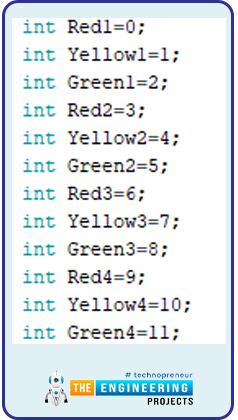
Figure 5: Arduino Code
The next declaration is of pedestrian lights. The syntax of pedestrian light declaration is illustrated as follows.
Figure 6: Arduino Code
Void Setup:
This part of the code along with the declaration part is run only once, we will use this to define output and input pins. This helps Arduino to understand which pins to take data from and which pins to write data on.
Since there is no input, we will only define traffic lights and pedestrian lights as output pins. The syntax to do this is shown in figure 7.
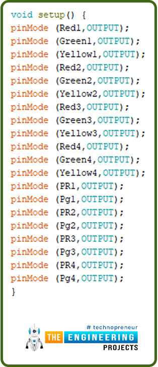
Figure 7: Arduino code, Void Setup
Void Loop:
This part of the code runs in a loop consistently and is used to write the main section of the code.
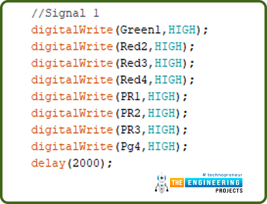
In the first section, we will turn on the green light of signal 1 while all other signals are red. The pedestrian lights are red for pedestrian signals 1, 2 and 3. While the pedestrian 4 light is green since it is opposite to traffic signal 1.
Figure 8: Arduino Code
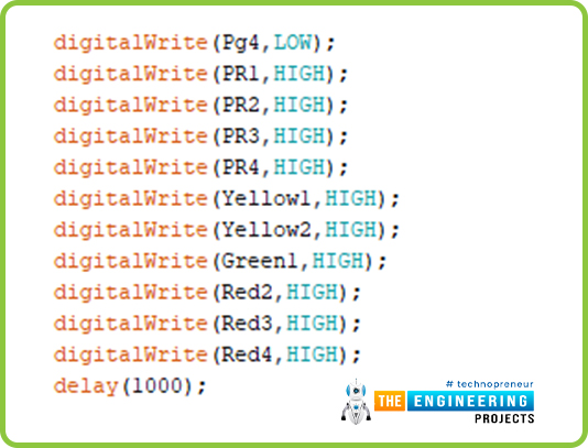
After a delay of 2000ms, we will turn on the yellow light for signal 1 and signal 2 to indicate that a transition from signal 1 to signal 2 will be made shortly. We will also turn all pedestrian lights red in order to ensure pedestrian safety.
Figure 9: Arduino Code
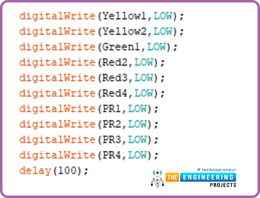
After a delay of 1000ms, all traffic and pedestrian lights will turn off for 100ms.
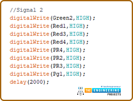
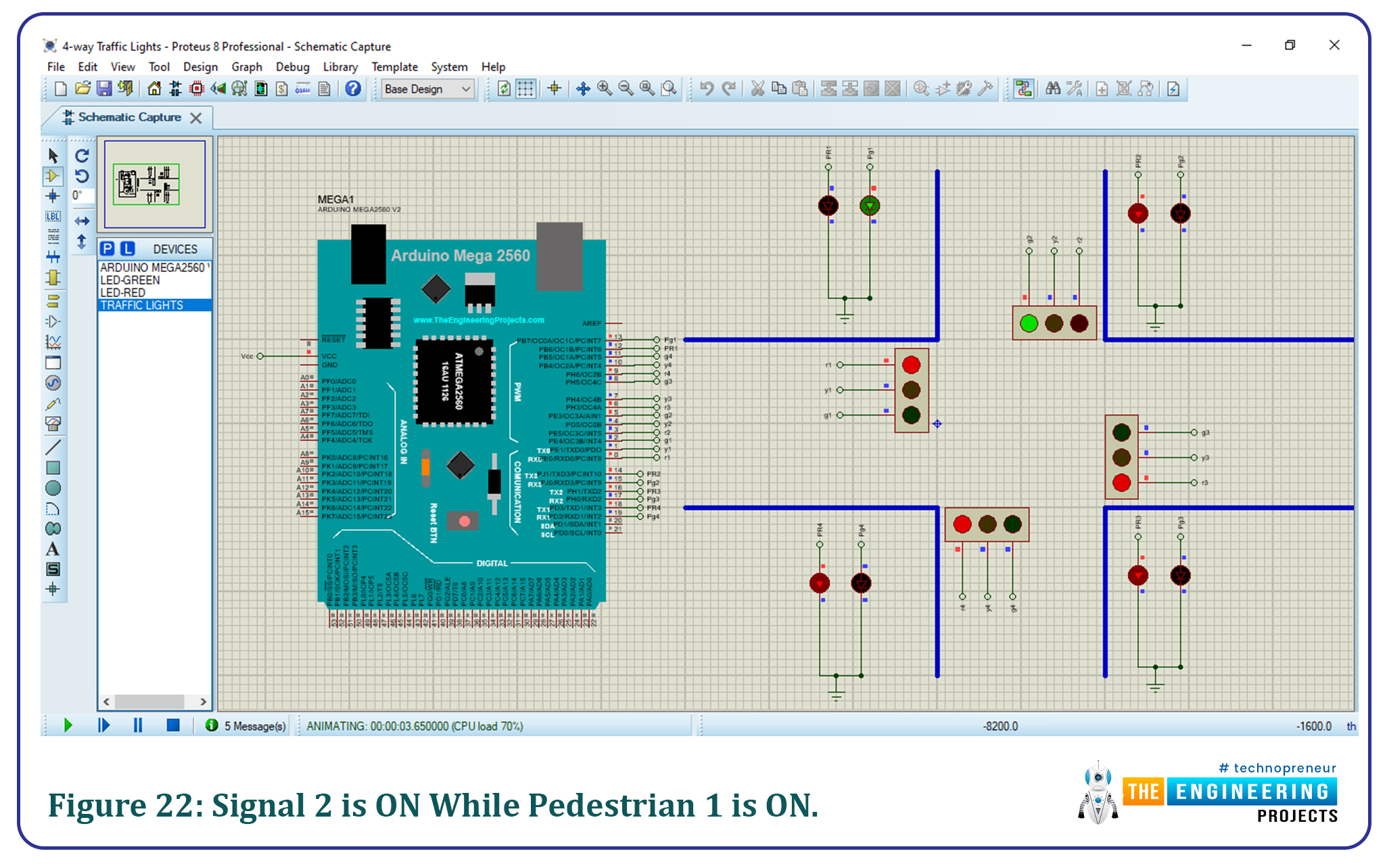
For the second signal, we will turn on the green light of signal 2 while all other signals are red. The pedestrian lights are red for pedestrian signals 2, 3 and 4. While the pedestrian 1 light is green since it is opposite to traffic signal 2.
Figure 11: Arduino Code
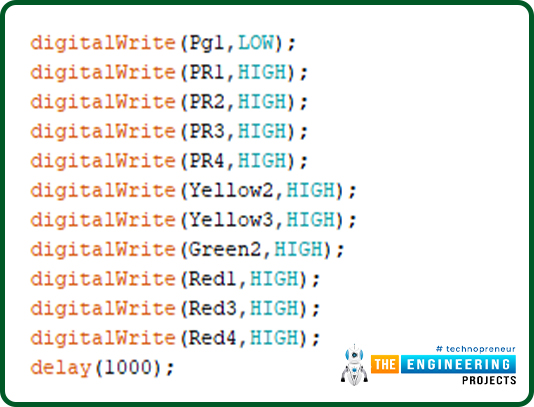
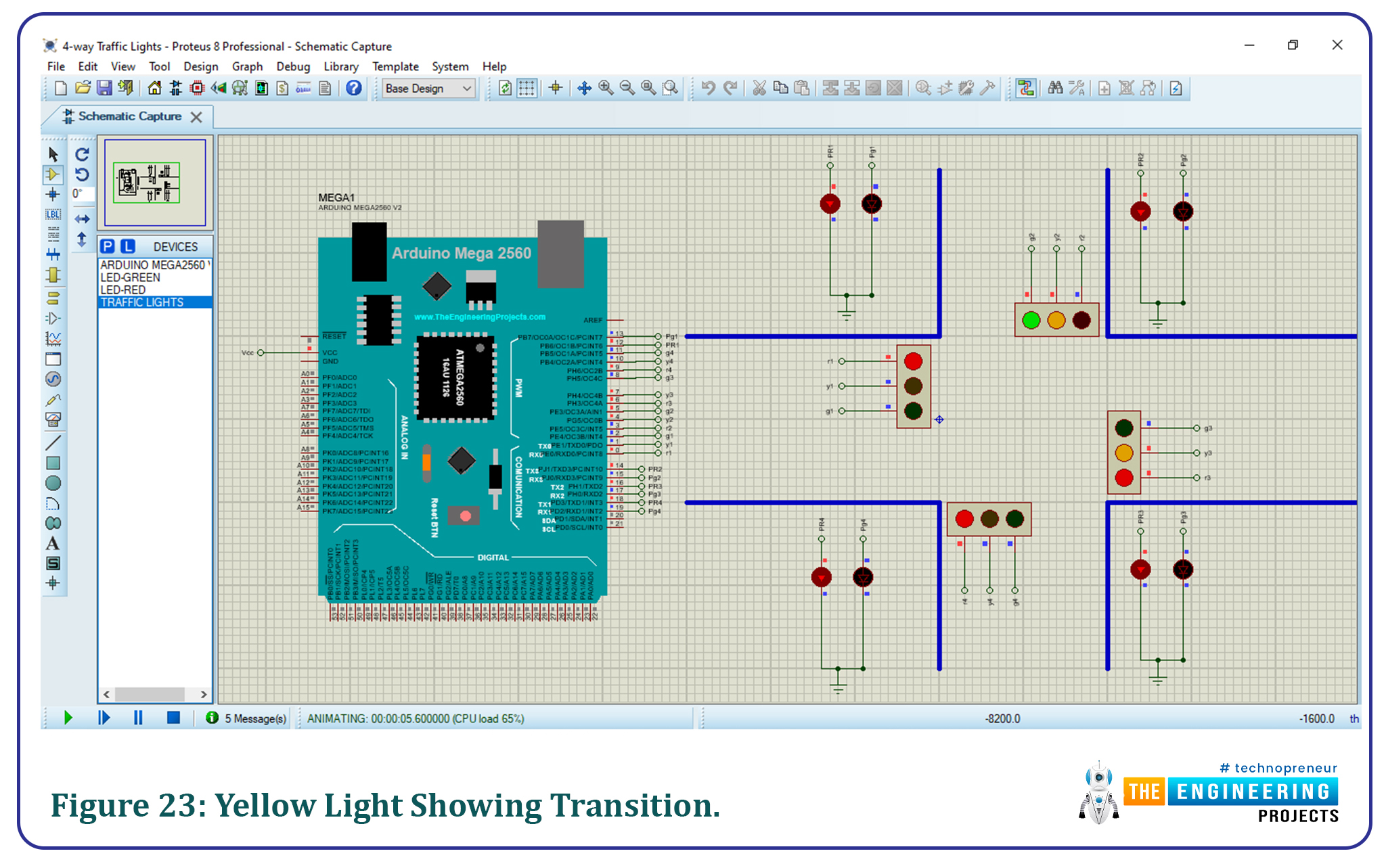
After a delay of 2000ms, we will turn on the yellow light for signal 2 and signal 3 to indicate that a transition from signal 2 to signal 3 will be made shortly. We will also turn all pedestrian lights red in order to ensure pedestrian safety.
Figure 12: Arduino Code
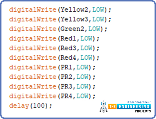
After a delay of 1000ms, all traffic and pedestrian lights will turn off for 100ms.
Figure 13: Arduino Code
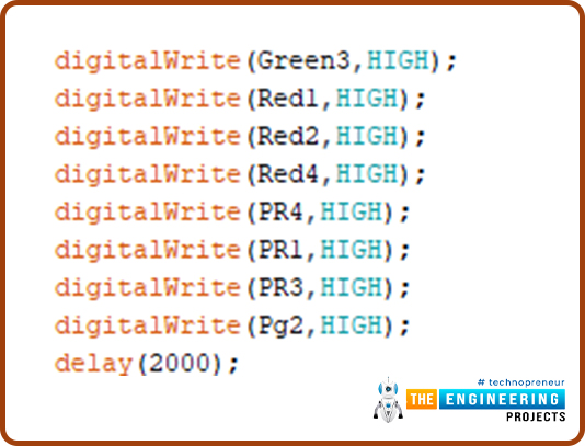
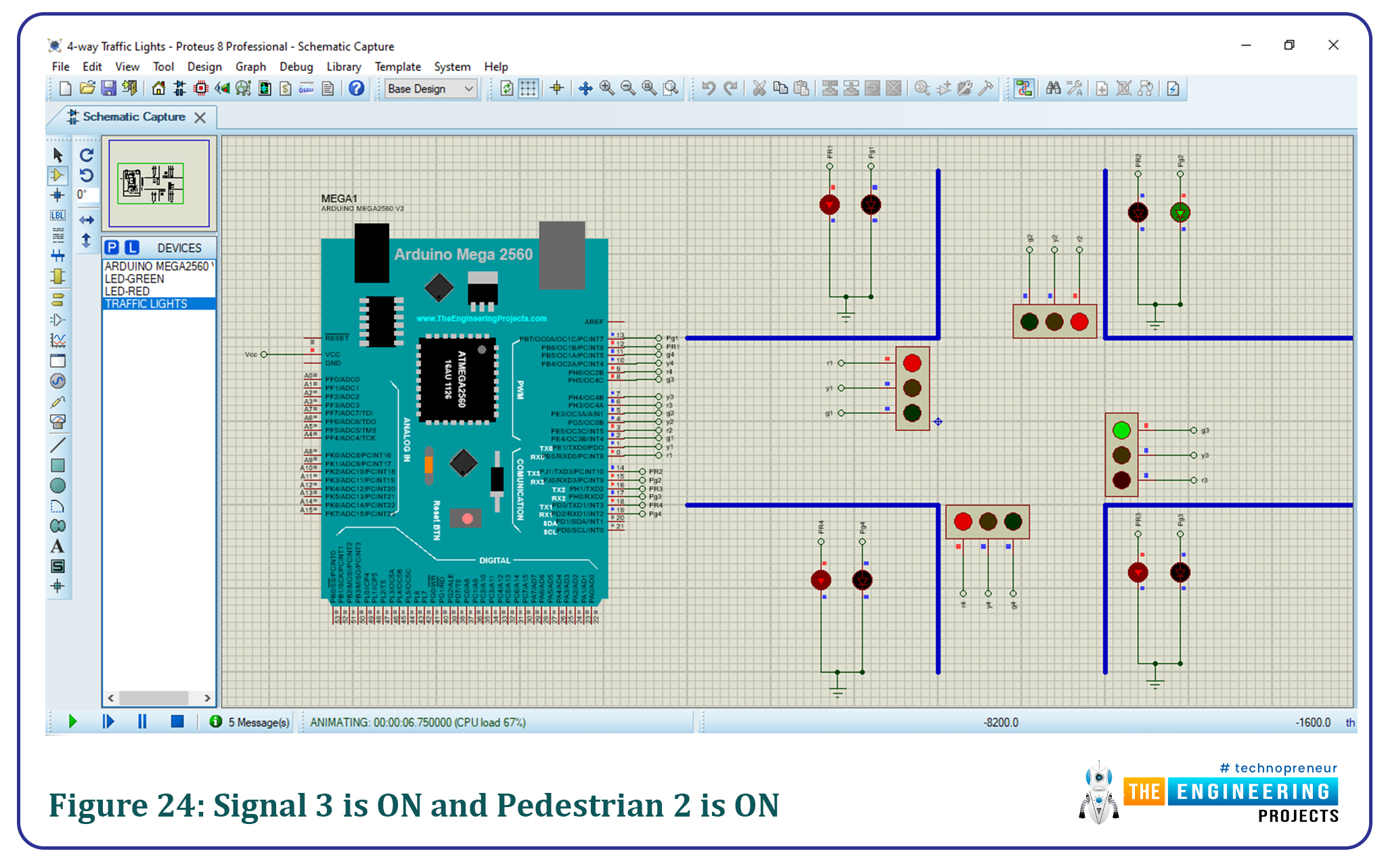
For signal 3, we will turn on the green light of signal 3 while all other signals are red. The pedestrian lights are red for pedestrian signal 1, 3 and 4. While the pedestrian 2 light is green since it is opposite to traffic signal 3.
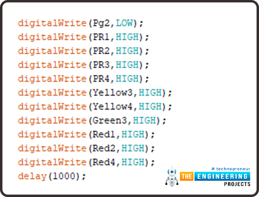
After a delay of 2000ms, we will turn on the yellow light for signal 3 and signal 4 to indicate that a transition from signal 3 to signal 4 will be made shortly. We will also turn all pedestrian lights red in order to ensure pedestrian safety.
Figure 15: Arduino Code
After a delay of 1000ms, all traffic and pedestrian lights will turn off for 100ms.
Figure 16: Arduino Code
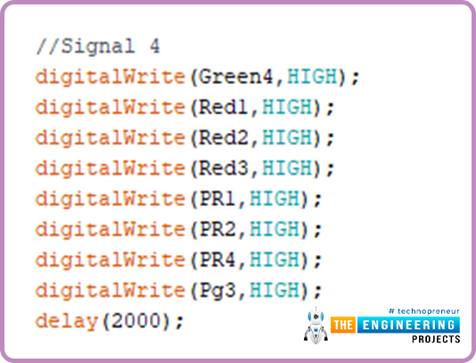
For the final signal, we will turn on the green light of signal 4 while all other signals are red. The pedestrian lights are red for pedestrian signals 1, 2 and 4. While the pedestrian 3 light is green since it is opposite to traffic signal 4.
Figure 17: Arduino Code
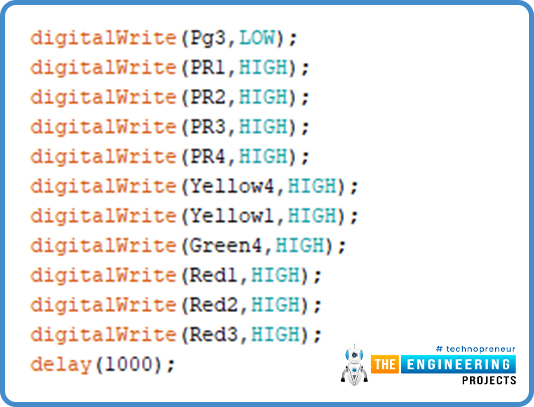
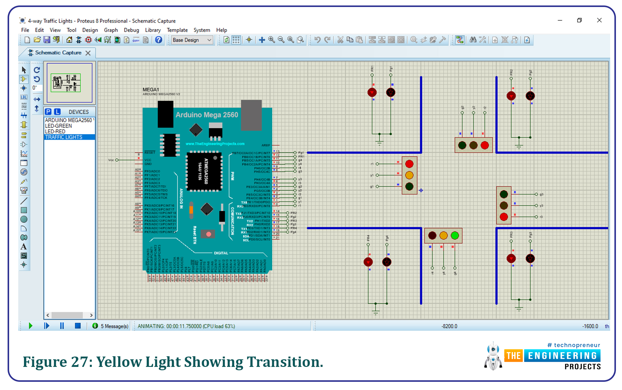
After a delay of 2000ms, we will turn on the yellow light for signal 4 and signal 1 to indicate that a transition from signal 4 to signal 1 will be made shortly. We will also turn all pedestrian lights red in order to ensure pedestrian safety. This will also complete the loop and the sequence will keep running on its own.
Figure 18: Arduino Code
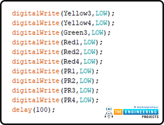
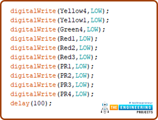
After a delay of 1000ms, all traffic and pedestrian lights will turn off for 100ms.
With this, the program of the void loop will end and start again from signal 1 on its own.
Results/Working:
Generate a hex file from the Arduino program made above. Be sure to select
Integrate the hex file into your Arduino board on Proteus.
Run the simulation.
The results of the simulation should be something like our simulation results.
The simulation results for each scenario are illustrated in the figure below.
At first, traffic signal 1 is turned ON and the green light is displayed for 2000ms. The green pedestrian light 4 is also turned ON since it is opposite to signal 1.
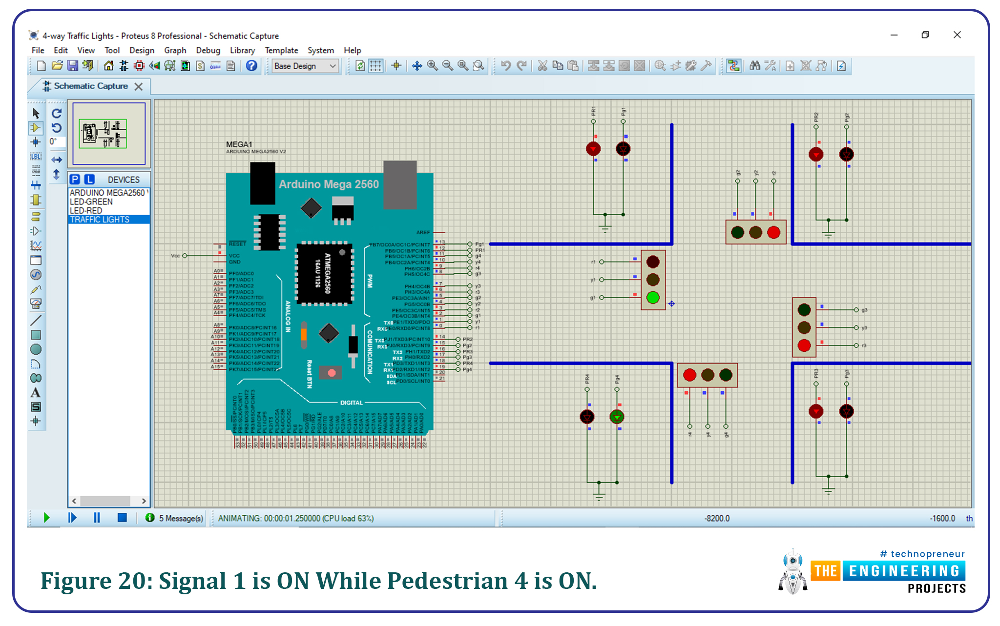
Figure 20: Signal 1 is ON while Pedestrian 4 is ON.
Then the yellow light of signals 1 and 2 are turned ON showing transition is about to happen. The red pedestrian lights during this are turned ON to ensure pedestrian safety.
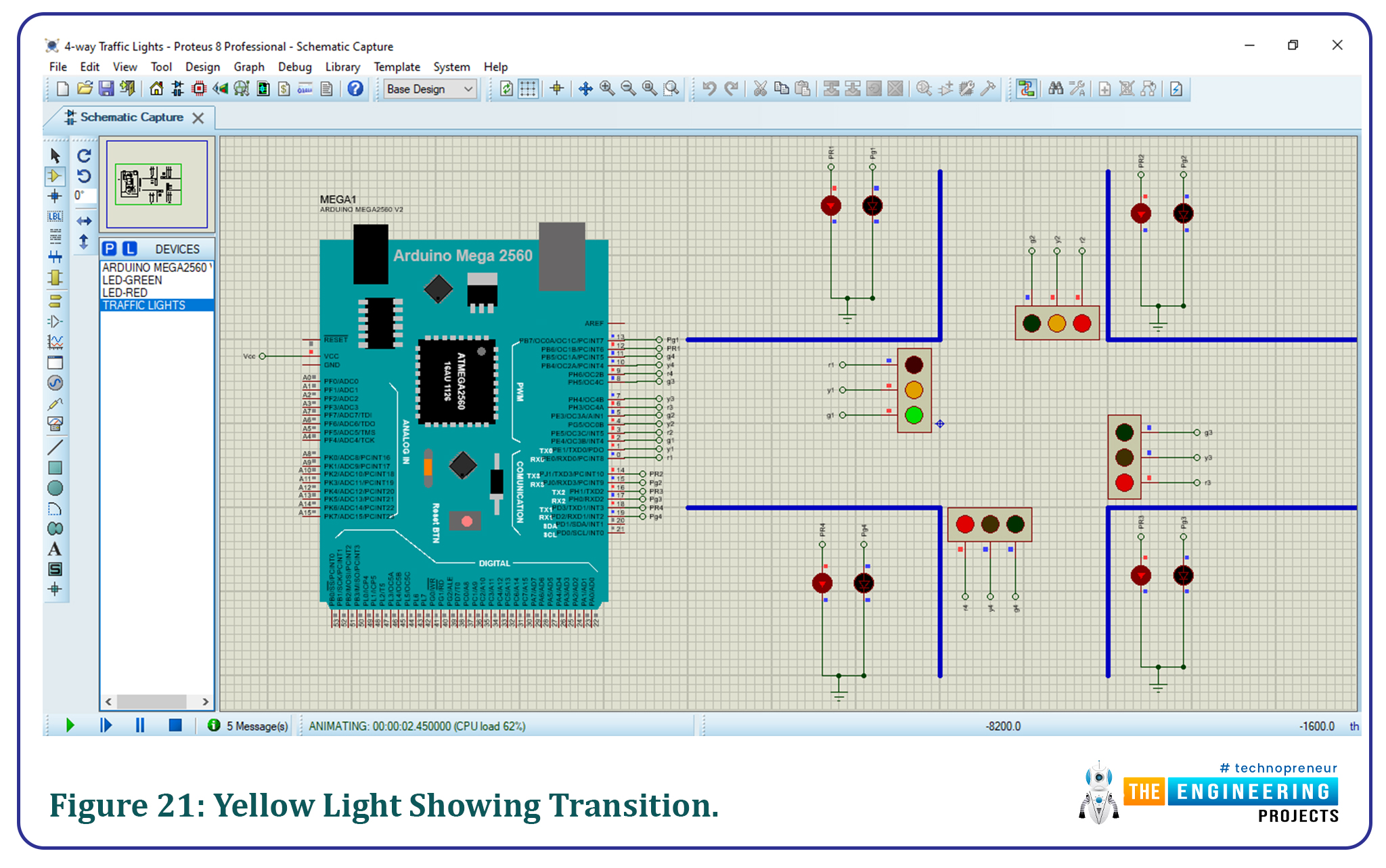
Then traffic signal 2 is turned ON and the green light is displayed for 2000ms. The green pedestrian light 1 is also turned ON since it is opposite to signal 2.
Figure 22: Signal 2 is ON while Pedestrian 1 is ON.
Then the yellow light of signal 2 and 3 is turned ON showing transition is about to happen. The red pedestrian lights during this are turned ON to ensure pedestrian safety.
Figure 23: Yellow light showing transition.
Then traffic signal 3 is turned ON and the green light is displayed for 2000ms. The green pedestrian light 2 is also turned ON since it is opposite to signal 3.
Figure 24: Signal 3 is ON and Pedestrian 2 is ON
Then the yellow light of signal 3 and 4 is turned ON showing transition is about to happen. The red pedestrian lights during this are turned ON to ensure pedestrian safety.
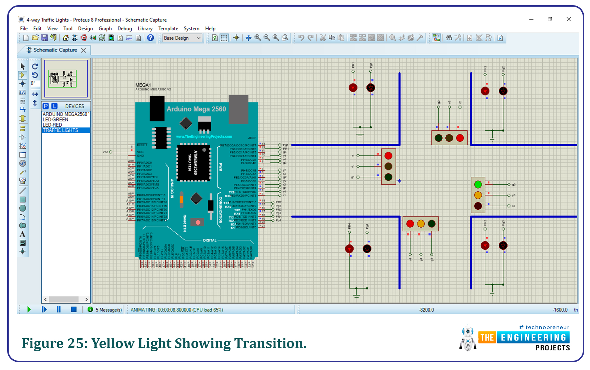
Then traffic signal 4 is turned ON and the green light is displayed for 2000ms. The green pedestrian light 3 is also turned ON since it is opposite to signal 4.
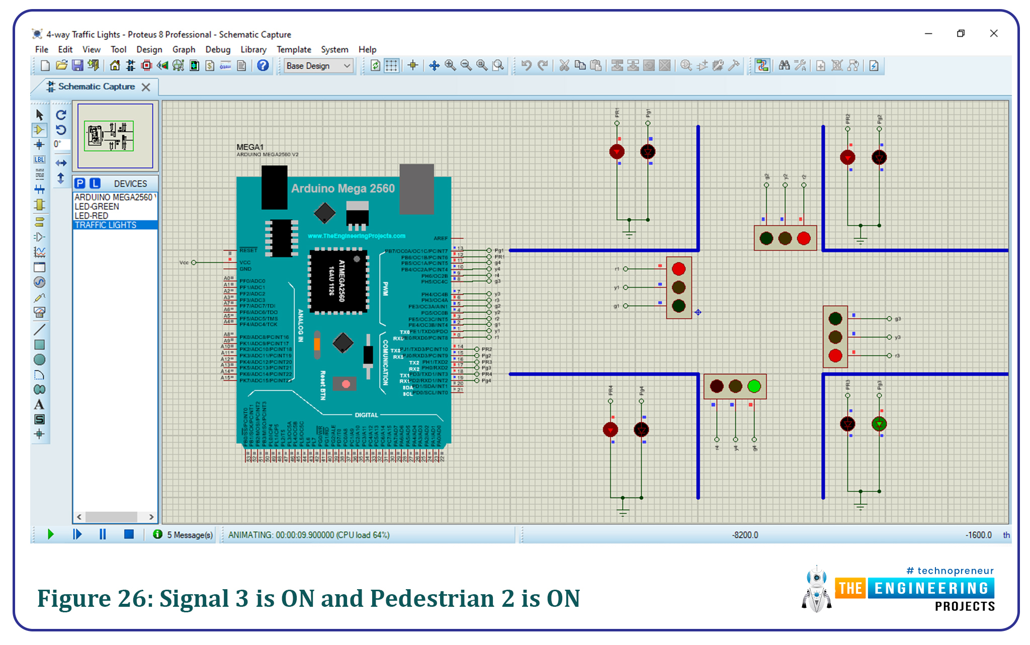
Figure 26: Signal 3 is ON and Pedestrian 2 is ON
Then the yellow light of signal 4 and 1 is turned ON showing transition is about to happen. The red pedestrian lights during this are turned ON to ensure pedestrian safety.

Figure 27: Yellow light showing the transition.
That is all for today’s tutorial, I hope you enjoyed learning with us. We wish you have a good day ahead of you. Thanks for reading.


