
We can use this project for an engineering project’s showcase for electronics, electrical engineering students, and can be used in offices as well.
Coffee is the second most popular drink in the world and it is one of the oldest beverages of the world. According to Wikipedia, more than 2 billion cups of coffee are consumed every day in the whole world. As engineers or working professionals, we all know how coffee is very important for us. Having a good coffee makes our day better and refreshes the mood. Research shows coffee drinkers tend to live longer but when keeping it in moderate consumption. And making a good coffee is one of the most skillful jobs and time-consuming processes as we want our coffee in minutes. Now here our project comes to the picture, this smart coffee vending machine can make a good coffee in a couple of minutes. There are various flavors of coffee and our smart coffee vending machine can provide us with 4 different flavors which are the most commonly loved such as Latte, Cappuccino, Espresso, and Cafe Mocha. Here's the video demonstration of this project:
| Where To Buy? | ||||
|---|---|---|---|---|
| No. | Components | Distributor | Link To Buy | |
| 1 | DC Motor | Amazon | Buy Now | |
| 2 | LCD 20x4 | Amazon | Buy Now | |
| 3 | Arduino Uno | Amazon | Buy Now | |
Software to Install:
As we are going to design this project using Proteus Simulation, instead of using real components. As in the simulation, we can figure out the issue which may occur while working on real components and that can damage our components.
Proteus is the software for simulation and designing electronics circuits. As Proteus software has a big database of electronics components but still it does not have few modules in it like Arduino boards or LCD modules etc.
So we have to install the libraries, which we are going to use in this project:
- Arduino Library for Proteus: We have to add the Arduino boards to the Proteus components list.
- LCD Library for Proteus: We have to add the LCD module to Proteus Suite.
Smart Coffee Vending Machine using Arduino
These are required components for Smart Coffee Vending Machine, as follows:
- 20X4 LCD display: It is used to display user-related messages like the state of the vending machine.
- Arduino UNO: It is used as the brain of our project. All operations and decision-making will be done using this microcontroller.
- DC motor: It is used for dispensing the ingredients of coffee and the mixer.
- Buttons: It is used as a user interaction option.
As a suggestion, whenever we make a project, it should be like a product, as it should be user friendly and interactive, so considering that we have used an LCD module to display the messages related to available coffee flavors and their individual prices so that users can easily select them using buttons and DC motors to pour the ingredients related to coffee like water, sugar, coffee powder, and milk, and a mixer for blending the coffee.
We have connected the LCD using an I2C GPIO expander as we have limited GPIO pins to connect other peripherals with Arduino UNO. I2C Gpio expander requires only two pins as we know that I2C uses SCL(Serial Clock) and SDA(Serial Data) pins for communication.
Components Needed:
- Arduino UNO
- LCD display
- 4 Buttons
- 8 Motors
- PCF8574
Components Details
Arduino UNO:
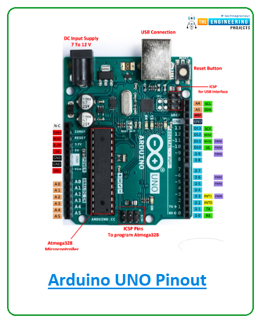
We can use any Arduino development board but here in this project, we have used an Arduino UNO board.
- Arduino UNO is one of the programmable, open-source microcontroller boards of the Arduino family.
- It contains an Atmel’s Microchip ATMega328 or ATMega328P microcontroller which has Harvard architecture 8-bit RISC processor core and 32 KB flash memory.
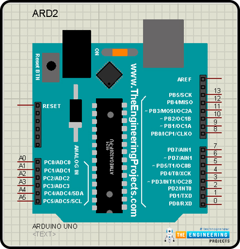
- Arduino UNO comprises 14 digital I/O pins out of which 6 are PWM pins as well and 6 Analog I/O pins with 10 bits resolution(0-1024).
- Arduino UNO has only 1 hardware UART pin(but we can use other pins also for UART communication using SoftwareSerial library in Arduino), 1 I2C, and 1 SPI.
PCF8574:
We have used this IC as a GPIO expander for our project as we have restrictions on the availability of GPIO pins in Arduino UNO.
- It is an 8-bit I/O, silicon-based CMOS GPIO expander.
- It can be used to write data on the pins and also can read data on those pins.
- It uses the I2C protocol for communication with the master device.
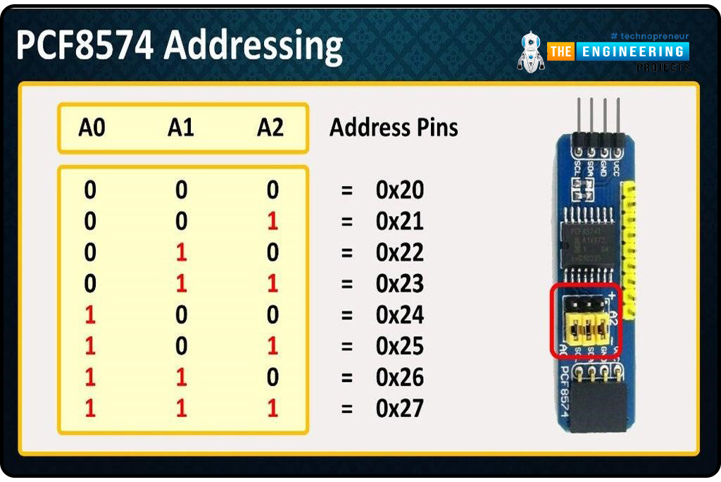
- As we know that I2C protocol uses the slave address to send or receive data from slaves, so for that it has 3 pins A0, A1, A2 for setting the slave address.
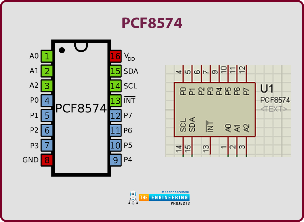
- Slave address for PCF8574 starts from 0x20 to 0x27. That means we can add only 8 PCF8574 IC directly to a master controller.
- The following image explains the logic of the slave address of PCF8574.
- It is used for connection for the LCD module with Arduino UNO in our project.
- If you want to learn more about IC PCF8574, you can refer to the datasheet using the following URL: PCF8574 Datasheet
LCD display
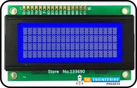
The LCD display is used to show the user-related messages in this project.
- LCD is a short form of Liquid Crystal Display which is basically built using Liquid Crystal technology.
- There are different sizes of LCDs available, in this project we have used 20X4 size.
- Here 20X4 signifies that it can display 80 ASCII characters at a time.
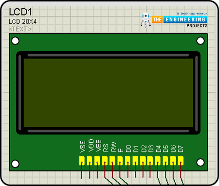
- There are 16 pins in the LCD. We will not use every pin of LCD in this project.
- It has 8 data pins, 1 Read/ Write select pin, 1 Register mode pin, 1 Enable pin, 2 pins for backlight, and 2 pins for power supply, 1 contrast control pin.
- There are mainly two types of register in the LCD: Command Register and Data Register.
- When we set the RS(Register Select) pin to logic High then it will select the data register mode and in logic Low, it will select the command register.
- To display the data on LCD we will set the RS pin to logic High.
Proteus Simulation of Smart Coffee Vending Machine :
Now, it's time to start designing the Proteus Simulation of our Smart Coffee Vending Machine.- Most importantly, ensure that Proteus is installed on your PC and download all the required libraries for Proteus ahead.
- For this project, we are going to need libraries of Arduino and LCD modules.
- Make sure that you have read about how to use libraries in Proteus software.
- We need the following components, so select all of them from the Proteus component library.

Circuit Diagram and Working:
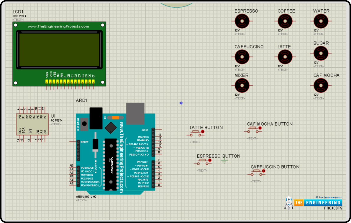
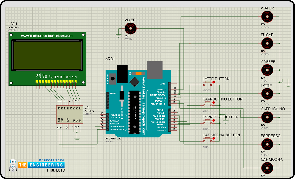
- Now let’s design our circuit, first place all the selected components in the Proteus Workplace, as shown in the image below:
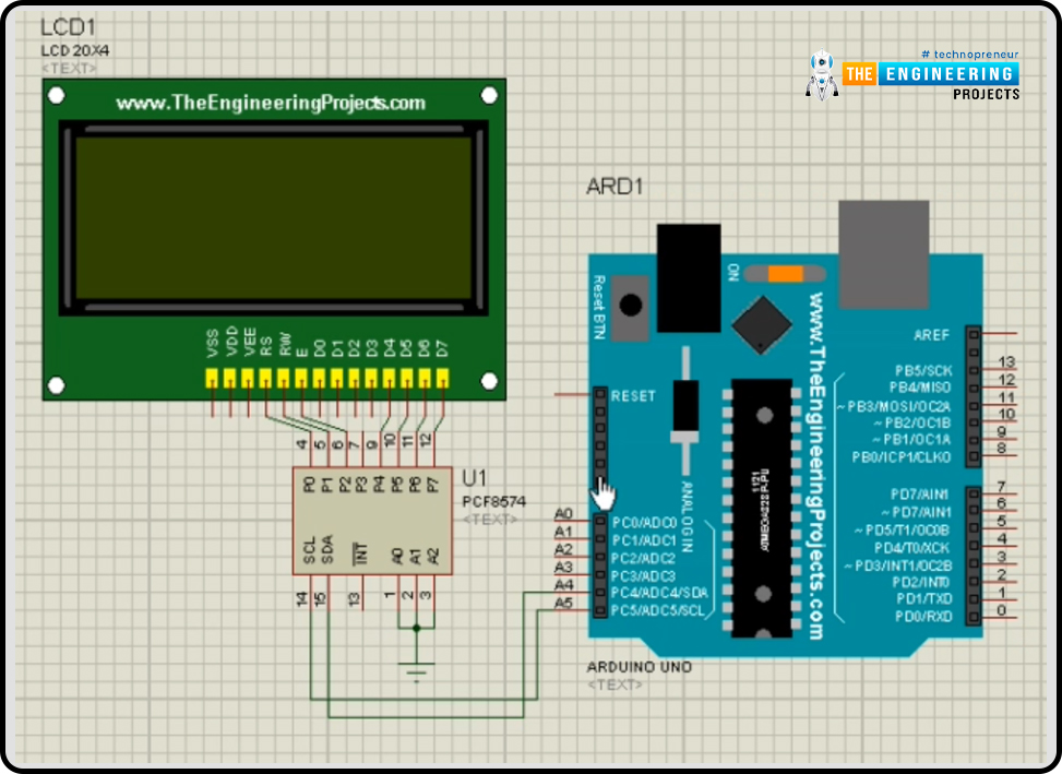
- We will start connecting the LCD module and PCF8574, as we are using only 4-data pin-mode of LCD.
- After that, we will start the GPIO expander PCF8574 I2C connections, connect the SDA, SCL pins of PCF8574 to Arduino UNO’s SDA, SCL pins which are A4, A5 pins of the development board.
- As we know, we have to set the slave address of PCF8574 using A0, A1, A2 pins. And in this project we are going to use the slave address 0x20, therefore for that, we have to connect all pins to the ground. (As we have already seen in the above PCF8574 addressing image)
- In the next step, we are going to connect the buttons to Arduino digital pins D2, D3, D4, D5 as "Latte", "Cappuccino", "Espresso", "Cafe Mocha" flavors respectively and another terminal of the buttons is connected to ground. As we are going to use the buttons inactive low condition which means, when we press the button it will give us a logical LOW state.
- There may be a doubt in your mind why we have not used any PULL-UP resistors with buttons because we will handle that in our code. Arduino UNO comes with an internal PULL-UP resistor of 20-50 KOhms.
- Now connect the dc motors for each container, Water, Coffee, and Sugar container’s motors are connected with Arduino’s digital pins D10, D12, D11 respectively. Connect the coffee outlet motors for each type of Latte, Cappuccino, Espresso, Cafe Mocha with digital pins D6, D7, D8, D9 respectively. And at last, connect the mixer with the D13 pin.
- As we have mostly completed the wiring part, the first thing which we must make sure of before going to start our simulation is that all components should have adequate power supply and ground. And ground must be common in the whole circuit.
Now we hope you have understood the connections and you have already done it, so it is time to move to the coding part of our project.
Arduino Code for Smart Coffee Vending Machine
If you already know about the syntax and structure of Arduino sketch, it's a good thing, but if you have not been familiarized yet, no need to worry, we will explain it to you step-by-step.
Arduino coding language mostly follow the syntax and structure of C++ programming language, so if you are familiar with C++, then it would be like a cup of cake for you to understand the code but still if you don’t have any background knowledge, you don’t have to worry again, we have your back.
Arduino Coding follows a strict structure, it has mainly two sections. we have to write our code in those two functions.
- void setup()
- void loop()
As we are going to explain the Arduino code, it would be easy to understand if you have opened the code in the Arduino IDE already.
Declaration code:
- When we start our code, we will first include all the required libraries which we are going to use in this project.
- So our first step would be to download the required libraries if they are already not pre-installed in the Arduino IDE.
- Mainly we will use only two libraries, one for LCD display and the other for I2C communication.
- And I2C related functions come in the Wire library which will be pre-installed in Arduino ID, we don't have to install it explicitly.
- For the LCD module, we will use the Liquid Crystal_I2C library that we have to install.
- We can install libraries related to Arduino from the Arduino IDE by going to ‘Sketch > Include Library > Manage Library’. Now in the library manager, we can search for our required libraries. We can install the libraries using zip files also.
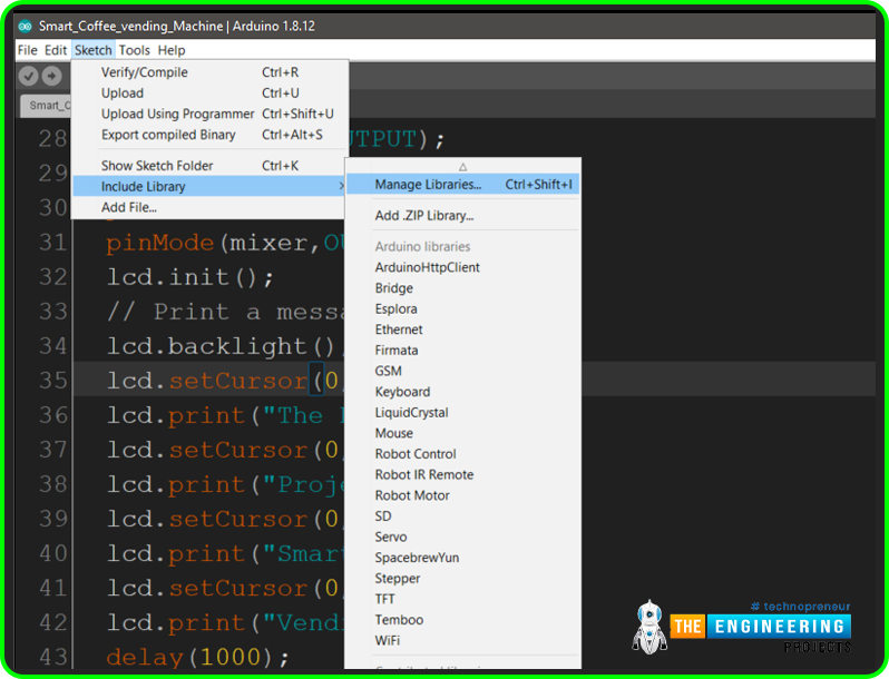
- >> Now, as we have installed all the required libraries. Let’s include them in our sketch.

- After that, we will define the pins which we are going to use in our project.
- We have to define them globally so that we can use them in all functions.
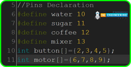
- You must be having a doubt why we have not defined pins for I2C.
- Because those pins are pre-defined in the Wire library, we can not assign any other pins for I2C communication.
- Now we will define and declare all the variables which are required in our project.
- There is an array for the price of a coffee with the size of 4, as we will only provide only 4 types of coffees and a string type variable for storing the name of flavors of coffee.

Arduino Setup() Function:
In this Arduino Setup() function, we will write a section of code that will only run once.- So mostly we will write the declarations, define the type of pins and initialize the peripherals such as the LCD module.
- We want to take user input from the buttons therefore we will declare them as INPUT type.
- We have not connected PULL UP resistors in buttons as you have read above, we will handle that in the code therefore we have declared it as INPUT_PULLUP mode.
- We have declared motor pins as OUTPUT mode because we want to control the motors.
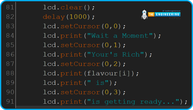
- After that we will initialize the LCD module then we will turn on the backlight of LCD, set the cursor to 0,0 index and using ‘lcd.print()’, we will print the welcome message on the LCD module.
- In the setCursor function, the first argument is used for X-Axis and the second argument is for Y-Axis.
- It will display the welcome message for 1 sec as we have given a delay for 1000 milliseconds after we clear the display.
Arduino Loop() Function:
Arduino Loop function runs after the the ‘void setup()’ function.- In this section, we will write the code which is required to run in a continuous loop. So we will write our main application code here.
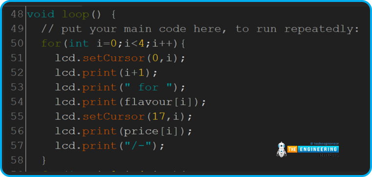
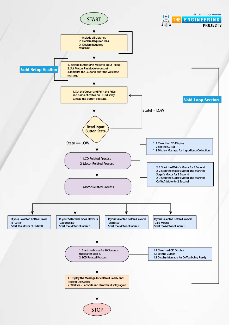
- So when the code reaches the void loop section, first we will display the flavor and the price of the coffee on LCD display as we want to show the user what type of coffee our vending machine makes and the price of those individually.

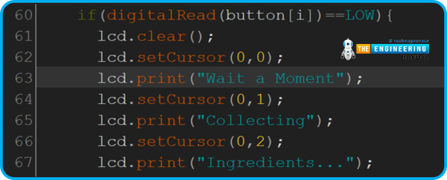
- As we have not cleared the display, it will display the same message.
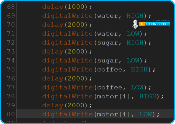
- After 1 second delay, we will start the water container motor for pouring the water for 2 seconds.
- Thereafter we will set the water’s container pin to LOW and Sugar’s container motor pin to HIGH for 2 seconds, similarly for the coffee’s container pin.

- Now we will start the motor for the selected flavor of coffee for 2 seconds and then stop it.
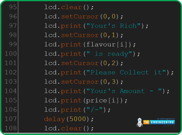
- As now our selected coffee is getting ready so we will display the message for the same.
- To display any new message, we have to clear our display with pre-occupied text.

- Now we will start the mixer motor for 10 seconds to mix all the poured ingredients.

Results/Working:
- Below is the Flow diagram of coffee vending machine:
- Let’s understand the code with an example, we will go with the starting step.
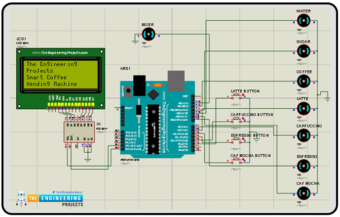
- Power ON the device, the machine will display the welcome message that you can change from that code as per your choice.
- That message will be shown for 1 second thereafter it will clear the display.
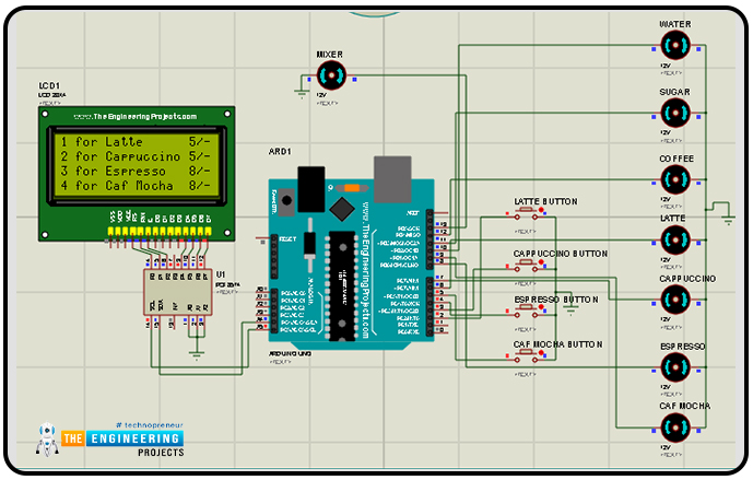
- Now it will display the type of coffee as "Latte", "Cappuccino", "Espresso", "Cafe Mocha" and their respective prices.
- Let’s suppose, the user wants to have a Latte today, so he/she will press the button for the same, thereafter our coffee-making process will start.
- The first LCD display will show the message “Wait a Moment Collecting Ingredients” and it waits for 1 second.
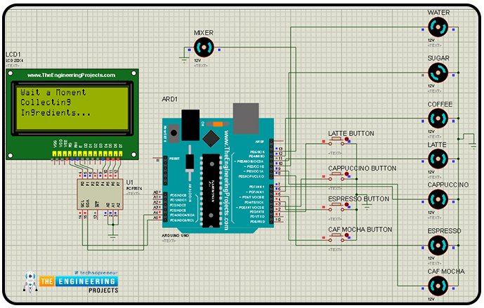
- Thereafter it will start pouring the water for 2 seconds, then it will stop that motor.
- After that, it will start to pour sugar for 2 seconds, then stop that motor.
- At last, it will start to pour the coffee for 2 seconds, then stop that motor.
- It will start the motor of the selected type of coffee to dispense the coffee to the container and then it will wait for 1 second.
- Now LCD will display the message for coffee getting ready as "Wait a Moment Your’s Rich Latte is getting ready…” as the user has selected Latte that’s why it shows “Latte is getting ready… “.
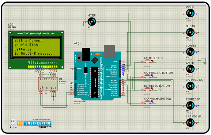
- Now we will start the mixer to mix all the ingredients for 10 seconds.
- Again we will clear the LCD display to show the message for prepared coffee as “ Your's Rich Latte is ready. Please Collect it Your's Amount - 5/-”.

- Then it waits for 5 seconds and clears the display and again shows the price and the available types of coffee.

- As Proteus requires the hex file of the code to run the simulation.
- So for that, open the Arduino IDE and please verify your code before making a hex file by clicking on the ‘Verify’ button to remedy any errors.
- To get the hex file from the Arduino IDE click on “Sketch > Export Compiled Binary”.
- Your hex file will be generated successfully now put that hex file to the Arduino UNO board in the Proteus software.
- Everything is now in place, it's time to run the simulation and get a nice virtual coffee.
I hope you have understood the whole working of our smart vending machine project and enjoyed it as well. I think we have explained pretty much everything but still if you have any doubts or improvements please let us know in the comment section.
Thanks for giving your valuable time for reading it.


