Hello friends, I hope you all are doing great. In today's lecture, we will have a look at the I2C Communication with STM32 Microcontroller board. I am going to use the Nucleo board for today's lecture. In the previous lecture, we have discussed STM32 Serial communication both in Interrupt Mode and polling Mode. Today, we will study another way of communication(i.e. I2C) with STM32. So, let's first have a look at what is I2C Communication:
| Where To Buy? | ||||
|---|---|---|---|---|
| No. | Components | Distributor | Link To Buy | |
| 1 | STM32 Nucleo | Amazon | Buy Now | |
What is I2C Communication?
I²C (Inter-Integrated Circuit) is a two-wire serial communication system used between integrated circuits. Like any serial protocol, one of its advantages is that of using only two lines that transmit or receive a sequence of bits, the limit is the communication speed which has been improved over the years.
The bus was conceived and developed by Philips (now NXP) It was designed to overcome the difficulties inherent in the use of parallel buses for communication between a control unit and various peripherals.
Serial transmission is a mode of communication between digital devices in which bits are sent one at a time and sequentially to the receiver in the same order in which they were transmitted by the sender. Although the communication modules are more complex than the parallel transmission, the serial mode is one of the most widespread especially in communications between chips that must communicate with each other over great distances, because:
- it requires fewer wires and pins available on the integrated circuit with a consequent reduction in costs and space on the board;
- is more tolerant of interference and transmission errors;
- up to 128 devices can be connected to each other

I2C Pinout
- SDA (Serial Data) is the line where master and slave send or receive the information (sequence of bit);
- SCL (Serial Clock) is the line dedicated to the clock to synchronize the data flow.
SDA and SCL lines need to be pulled up with resistors. The value of these resistors depends on the bus length ( ie the bus capacitance) and the transmission speed. The common value is 4.7kO. In any case, there are many guides to size them and we refer their reading to the more attentive reader.
The transmission mode is Half-duplex ie the transmission between devices is alternated.
As shown by the previous image, we can use this communication to put in communication different peripherals as Analog-Digital Converters (ADCs), Digital-Analog Converters (DACs), EEPROM memories, sensors, LCD screen, RF module, Real-Time Clock, etc.
I2C Communication in STM32
The Nucleo boards provide one or more I2C interfaces that can be quickly configured with STCube Tool.
There are four modes of operation:
- Slave Transmitter
- Slave Receiver
- Master Transmitter
- Master Receiver
The first two are used to operate in slave mode, while the last two are in master mode. By default, the interface is configurated in slave mode.
By default, the I2C interface operates in Slave mode, but it is possible to switch to Master mode to send a Start condition message. Furthermore, it needs to write in I2C_CR2 register the correct clock configuration to generate the expected timings. The Master sends a Stop condition when the last data byte is transferred, and the interface generates an interrupt.
I2C Packet Message
In general, the packet message is as follow:

- Start condition: the master pulls SDA low and SCL is High to inform slave devices that a transmission is ready to start.
- Address frame: the master sends the address of the slave, each device has an address of 7-10bit, then sends the Read (R) or Write (W) bit, which are respectively 1 and 0. Finally, the master waits that the slave sends the Acknowledge bit (ACK).
- Data frame(s): Send (master) / Receive (slave) Data Byte (DATA) and then Waiting (master) / sending (slave) the Acknowledge bit (ACK)
- Stop condition: the master sends the stop conditions pull SDA to High defined by a low while SCL remains high.
I2C Modes in STM32
Furthermore, there are three ways to exchange data, named:
- Polling Mode
- Interrupt Mode
STM32 I2C Polling Mode
- In polling mode, also called blocking mode, the application waits for the data transmission and reception.
- This is a simple way to communicate between devices when the bit rate is not very low, for example when we can debug the board and we want to display the result on screen console.
HAL library provides the following functions to transmit and receive in polling mode:
I2C Master Reciever
- The function to receive data in master mode is as follows:
HAL_I2C_Master_Receive(I2C_HandleTypeDef *hi2c, uint16_t DevAddress, uint8_t *pData, uint16_t Size, uint32_t Timeout)The parameters are:
- hi2c is a pointer to an I2C_HandleTypeDef structure that contains the configuration information for the specified I2C.
- DevAddress is device address: The device 7 bits address value in the datasheet must be shifted to the left before calling the interface.
- pData is a pointer to data buffer.
- Size is the amount of data to be sent.
- Timeout is the timeout duration.
I2C Master Transmitter
- Master transmits in master mode an amount of data in blocking mode.
HAL_I2C_Master_Transmit(I2C_HandleTypeDef *hi2c, uint16_t DevAddress, uint8_t *pData, uint16_t Size, uint32_t Timeout)
I2C Slave Reciever
- The function to receive data in slave mode is as follows:
HAL_I2C_Slave_Receive(I2C_HandleTypeDef *hi2c, uint16_t DevAddress, uint8_t *pData, uint16_t Size, uint32_t Timeout)
I2C Slave Transmitter
- The function to transmit data in slave mode is as follows:
HAL_I2C_Slave_Transmit(I2C_HandleTypeDef *hi2c, uint16_t DevAddress, uint8_t *pData, uint16_t Size, uint32_t Timeout)
I2C Memory Read
- Master reads an amount of data in blocking mode from a specific memory address.
HAL_I2C_Mem_Read(I2C_HandleTypeDef *hi2c, uint16_t DevAddress, uint8_t *pData, uint16_t Size, uint32_t Timeout)The additional parameters are:
- MemAddress is the internal device address.
- MemAddSize is the size of the internal device address.
I2C Memory Write
- Master reads an amount of data in blocking mode from a specific memory address.
HAL_I2C_Mem_Write(I2C_HandleTypeDef *hi2c, uint16_t DevAddress, uint8_t *pData, uint16_t Size, uint32_t Timeout)
STM32 I2C Interrupt Mode
- In interrupt mode, also called non-blocking mode, in this way the application waits for the end of transmission or reception.
- It is used when the transmission is not used continuously with respect to the activity of the microcontroller.
HAL_I2C_Master_Receive_IT(I2C_HandleTypeDef *hi2c, uint16_t DevAddress, uint8_t *pData, uint16_t Size)Master receives in master mode an amount of data in non-blocking mode with interrupt.
HAL_I2C_Master_Transmit_IT(I2C_HandleTypeDef *hi2c, uint16_t DevAddress, uint8_t *pData, uint16_t Size)Master transmits in master mode an amount of data in non-blocking mode with interrupt.
HAL_I2C_Slave_Receive_IT(I2C_HandleTypeDef *hi2c, uint16_t DevAddress, uint8_t *pData, uint16_t Size)Slave receives in master mode an amount of data in non-blocking mode with interrupt.
HAL_I2C_Slave_Transmit_IT(I2C_HandleTypeDef *hi2c, uint16_t DevAddress, uint8_t *pData, uint16_t Size)Slave transmits in master mode an amount of data in non-blocking mode with interrupt.
STM32 I2C DMA Mode
- DMA mode is the best way the exchange data, especially when we want to exchange data quickly and continuously that often require access to memory.
HAL_I2C_Master_Receive_DMA(I2C_HandleTypeDef *hi2c, uint16_t DevAddress, uint8_t *pData, uint16_t Size)Master receives in master mode an amount of data in non-blocking mode with DMA.
HAL_I2C_Master_Transmit_DMA(I2C_HandleTypeDef *hi2c, uint16_t DevAddress, uint8_t *pData, uint16_t Size)Master transmits in master mode an amount of data in non-blocking mode with DMA.
HAL_I2C_Slave_Receive_DMA(I2C_HandleTypeDef *hi2c, uint16_t DevAddress, uint8_t *pData, uint16_t Size)Slave receives in master mode an amount of data in non-blocking mode with DMA.
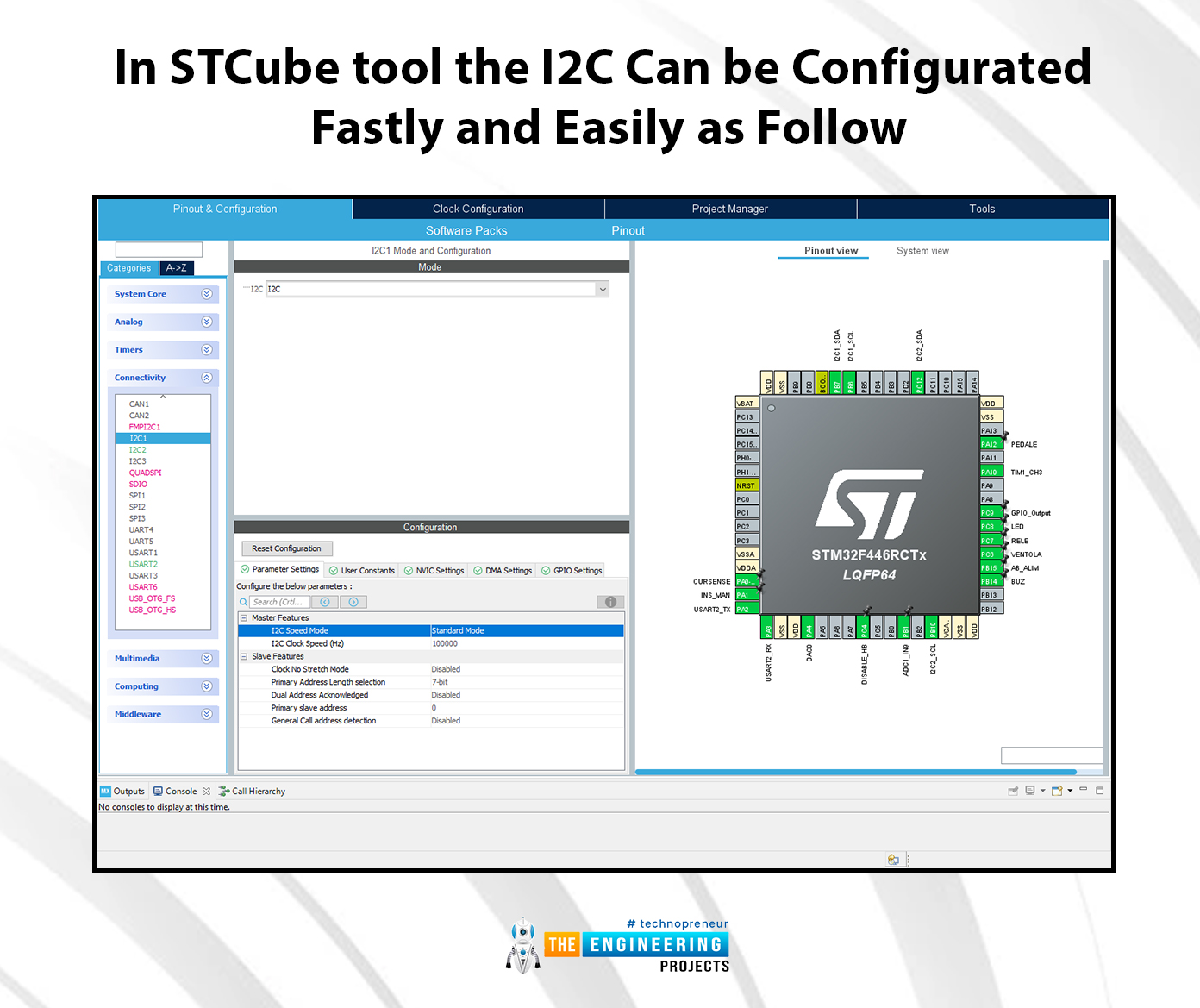
HAL_I2C_Slave_Transmit_DMA(I2C_HandleTypeDef *hi2c, uint16_t DevAddress, uint8_t *pData, uint16_t Size)Slave transmits in master mode an amount of data in non-blocking mode with DMA. In the STCube tool, the I2C can be configurated fastly and easily as follow.

In Pinout & Configuration, widow selects Connectivity and selects one of the available I2C (I2C1, I2C2, etc). In parameter settings, the master and slave features can be set. Master features are I2C speed mode (standard mode by default and fast mode) and the I2C clock speed (Hz). In standard mode, the device can send up to 400kbit/s while in fast mode up to 1Mbit/s. In general, like clock speed, the STM32 supports 100kHz, 400kHz and sometimes 1MHz.
The main feature of slaves is the primary address length that in general, as previously said, is 7-Bit. Furthermore, the slave can have a secondary address.
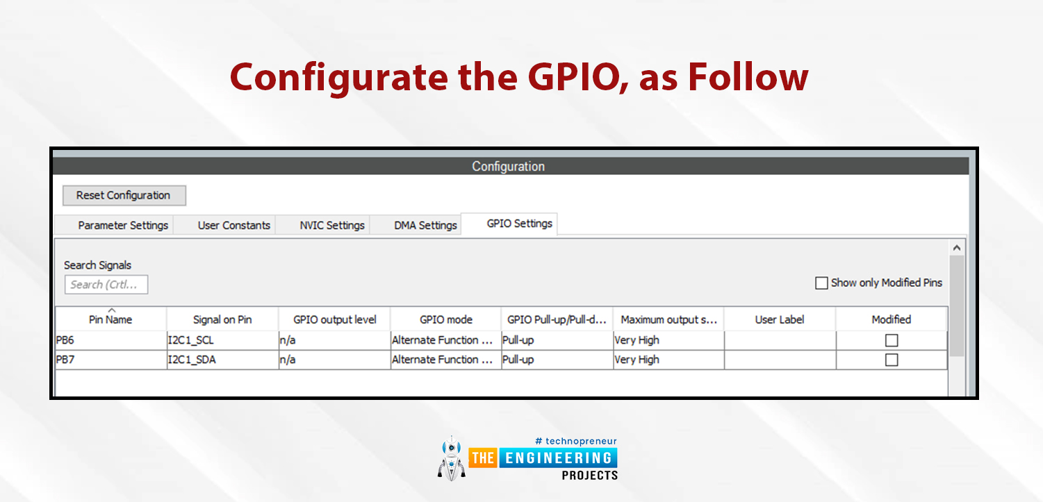
Then need to configure the GPIO, as follow:

Now the I2C configuration is terminated and can be possible to generate the code initialization and finally be ready to write our application.


