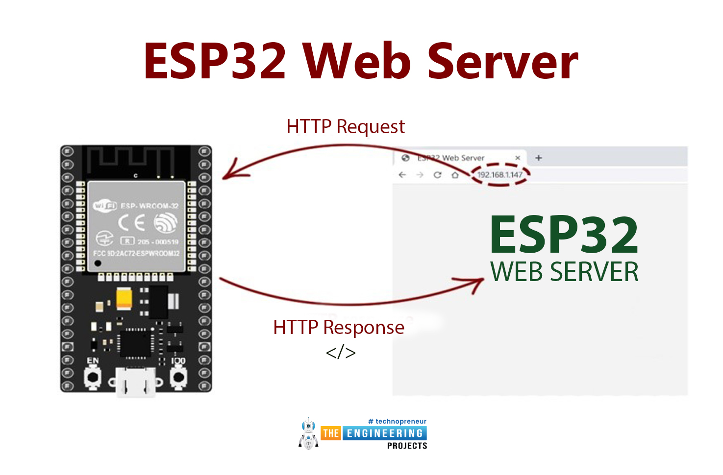
Hello readers, I hope you all are doing great. Today, we are going to start the second section of the ESP32 tutorial series and today's our first tutorial, where we will have a look at How to Create a Web Server with ESP32. In our previous tutorial, we introduced you to the basics of the ESP32 microcontroller. where we discuss How to set up Arduino IDE to program ESP32. In this tutorial, we will discuss creating a web server using the ESP32 module.
One of the most interesting features of the ESP microcontroller series is its wireless connectivity via WiFi & Bluetooth. Wireless connectivity protocols supported by ESP32 are:
- Wi-fi: 802.11b/g/n/e/i
- Bluetooth : BLE(Bluetooth low energy) and V4.2

| Where To Buy? | ||||
|---|---|---|---|---|
| No. | Components | Distributor | Link To Buy | |
| 1 | ESP32 | Amazon | Buy Now | |
What is a Web server?
A web server is software or hardware that stores, processes, and delivers web pages to users on request. In other words, it serves users all over the World Wide Web (www). The web server uses the hypertext transfer protocol (HTTP or HTTPS) for communication with the clients(normally, web browsers). We know that HTTP is a set of rules to format and exchange messages.

The following are some important features of a web server:
Features of a Web Server
- A web server, either physical or virtual, is a computer that hosts one or more websites.
- The HTTP protocol is the foundation of any data exchange within the network when using the server. So a web server uses it to communicate with the client.
- The web server uses static content and the files do not change dynamically. Some such files used in a web service are:
- HTML files
- Images
- Stylesheets
- JavaScript files
- The web server has multiple settings to avoid unnecessary attacks. This helps to maintain the health and integrity of a website. There are multiple types of web security attacks, such as:
- DDoS attacks
- SQL injection
- Cross-site scripting (XSS)
Hence, a web server has multiple features to serve the users on the web.
Web Server & Client Communication
A client is an entity that initiates communication with the web server and then the server provides the information required. In simple words, the client is a program, device, or user that requests services or resources from the devices, such as the web server. The communication and relationship between these two is called the server-client model. The following are the general server-client model steps that will help to understand the whole scenario:
The client sends an HTTP request to the server. The request includes the URL of the web page that the client wants to retrieve.
- The client (when the user requires data) sends an HTTP request to the server. This request may include the URL of the web page from which the client wants to retrieve the information.
- The server receives the request instantly and processes it. It does it when it looks up the URL saved in its database to find the corresponding web page file a client requires.
- If the web page file is found, the server sends it back to the client in the form of an HTTP response. This response also includes other important types of information, such as the page's content type and expiration date, etc.
- The client then receives the response and renders the web page on the user's screen. The client uses the content type information to determine how to display the web page.
- If the page is not found in the URL database, the server shows the error.
Web browsers like Chrome, Firefox, and Safari are examples of clients.
ESP32 as a Web Server
The ESP32 is a microcontroller famous for its wireless capabilities, which makes it ideal for a large number of fields, especially IoT. We are talking about WiFi connectivity as a web server and here are the key features of this module related to it:

- The ESP32 is made under the IEEE 802.11b/g/n standards; therefore it has a 2.4 GHz frequency band. Therefore, it can be used as:
- Common WiFi routers
- Access point
- The built-in WiFi capabilities of the ESP32 allow it to be used as a server and carry out the easiest and most effective communication at a distance without any physical connection.
- It has three operating modes:
- In station mode, the ESP32 is operated as a WiFi client. It means it can be connected to the existing Wi-Fi network. (We are covering today)
- In access point mode, it is operated as a WiFi access point; therefore it allows other devices to create a connection with it. (will be covered in the next lecture)
- In dual mode, it can act as a server and as a client and allow the features of both at the same time. (will be covered in the 3rd lecture of section 2)
- It has a dual processor that helps in handling multiple tasks at the same time. Therefore, ESP32 is more capable of managing a large network of devices and making it responsive for concurrent connections.
- It has asynchronous web server libraries, such as “ESPAsyncWebServe” to handle the HTTP requests asynchronously. These are useful because they allow it to effectively manage the connections without blocking the execution of other tasks.
- ESP32 has multiple security protocols that are used when creating the web server. As a result, it provides secure and protective communication between the devices.
- It has over-the-air updates, which means it can update the device's firmware without physically accessing it. It helps with remote updates and maintenance.
- The ESP32 is suitable for use as a server because of its multiple features, including:
- It can serve static files
- It can handle different HTTP methods (GET, POST, etc.)
- It supports features like server-side scripting
- The WebSockets feature of ESP32 allows it to carry out bi-directional communication between servers and clients. You will learn about both of these in just a bit.
- The ESP32 supports WiFi Direct, which is also referred to as the Peer to Peer (P2P); therefore, it can form a direct connection with other devices with no need for an external WiFi network.
ESP32 WebServer Working Principle
We know that the ESP32 has a built-in WiFi feature. This makes it suitable to use as a server. The example of the server-client relationship we have just discussed shows the internet connection of the whole world. The ESP32 can be used for the intranet connection, which is defined as:
"An intranet is a private network that has limited functionalities and is only accessible to users within a specific organization/location."
Usually, this network may consist of different devices, such as mobile phones, computers, laptops and tablets. The Arduino IDE is for the programming of the ESP32, just like we have done in the previous session. If your Arduino IDE is ready with the boards and ports, then let us try the built-in example of the ESP32 to use as a server.
What is an SSID?
- An SSID is a service set identifier that is the unique name of a wireless local area network (WLAN).
- It can be 32 characters long.
- It may include numbers, letters, and signs.
- The SSID can be set by the user as well.
- In simple words, the SSID is the name of the WiFi connection people use for their connection.
In the experiment we are just performing, the user has to replace the SSID with their own SSID to connect with the ESP32.
Using the ESP32 Server Built-in Example
Using the ESP32 as a server is easy with the web server example. It has the basics, and here are the steps to follow:
- Open the Arduino IDE.
- Connect the esp32 to your system through the cable. Make sure the ESP32 is connected accurately.
- Click on tools>boards>ESP32>Node32s. This is my board and you can choose according to the model of ESP32.
- Go to the files> examples>examples of Nose32s>WiFi and from the side menu, choose “SimpleWifiServer".
- It will create a new project with the code in it to run the ESP32 (connected to your system) as a server.
- Press the encoder (EN) button of the ESP32.
- Change the SSID and password according to your choice. In my case, it is PTCL-BB.
- Go to lines 38, 103, and 106 by one and replace the pin “5” digit with pin “2” because the built-in light is at pin 2.
- Replace lines 70 and 71 with the following:
client.print("Click <a href=\"/H\">here</a> to turn the LED on pin 2 on.<br>");
client.print("Click <a href=\"/L\">here</a> to turn turn the LED on pin 2 off.<br>");
- All the instructions are given in the code. Go to line 30 and place your SSID there.
- Go to line 31 and enter the password of your choice.
- Read the code carefully and hit the “verify” button.
- Once the code is compiled, press "Boot" on the ESP32 when the uploading process is carried out.
- Wait for the loading to complete.
- Click on the “Serial Monitor” button at the upper right corner of the screen to open the monitor. You can go to Tool>Serial Monitor for the same task.
- Choose the baud rate of 115200 from the drop-down menu at the right corner of the monitor.
- Right now, the monitor is blank:
- Click the EN button on the EPS32 to see the information.
- Now that the monitor has data and is loading, it starts to connect with the WiFi connection of the system.
- Once the loading is complete, it will provide the IP address. Copy this address.
- Go to the new tab in the browser and paste the address there.
- You will see that merely placing the “H” or “L” just after the IP address (as given in the code comment) will turn on and off the LED on ESP32 according to the URL.
Note: Make sure you have installed the port and board before you try this code and have selected all the right options; otherwise, you can face errors.
ESP32 Server as Messenger
- The ESP32 can be used to send the message through the browser.
- The microcontroller connects to the internet connection of the system.
- The serial monitor shows the IP address.
- The ESP32 acts as a server and through the URL of the browser, the user will send the message to the Arduino IDE.
- This message will be shown on the serial monitor.
- The user can change the message through the URL pasted in the web browser.
Material Required
- Internet connection
- System (e,g, laptop)
- ESP32 microcontroller
- Connecting cable
Code for ESP32 as Server
#include <WiFi.h>
const char *ssid = "My-SSID";
const char *password = "My-Password";
WiFiServer server(80);
void setup() {
Serial.begin(115200);
WiFi.begin(ssid, password);
while (WiFi.status() != WL_CONNECTED) {
delay(1000);
Serial.println("Connecting to WiFi...");
}
Serial.println("Connected to WiFi");
Serial.println("IP address: ");
Serial.println(WiFi.localIP());
server.begin();
}
void loop() {
WiFiClient client = server.available();
if (client) {
Serial.println("New Client.");
while (client.connected()) {
if (client.available()) {
String request = client.readStringUntil('\r');
client.flush();
// Check if the request contains a specific message
if (request.indexOf("GET /message") != -1) {
int startPos = request.indexOf("message=") + 8;
int endPos = request.indexOf("HTTP/1.1") - 1;
String message = request.substring(startPos, endPos);
Serial.println("Received message: " + message);
// Send a proper HTTP response
client.println("HTTP/1.1 200 OK");
client.println("Content-type: text/plain");
client.println("Connection: close");
client.println();
client.print("Message received!");
// Close the connection
client.stop();
Serial.println("Client disconnected.");
break;
}
}
}
}
}
Procedure
- Connect the ESP32 to the system using the cable.
- Open the Arduino IDE.
- Create a new project and remove the current code.
- Make sure you have the respective port and board installed successfully.
- Connect the right port and board.
- Paste the code given above into the new project.
- "Verify" the code by using the button.
- Once verified, compile and upload the code.
- Once the code is compiled, press the Boot button.
- Once the installation is completed, go to the serial monitor.
- Press the EN button.
- The serial monitor will show the information. Copy the IP address shown on the end of loading.
- The general ULR for sending the message through the server is given as: http://esp32-ip-address/message?message=Hello
- To send the “Hello” message to the ESP32 through the browser, use your IP address and the message. In my case, I am pasting the following URL in the browser: http://192.168.43.251/message?message=Hello
- Once reloaded, go to the serial monitor and check for the message:
- You can change the message through the URL.
http://192.168.43.251/message?message=I_am_using_The_Engineering_Projects
- This will create the following output:
How ESP32 WebServer works with hardware?
- For the demonstration purpose, we will create a webpage and will launch it through our ESP32 module, so ESP32 will be acting as a web server, serving the page.
- This webpage will have 3 Buttons on it, which will be controlling three LEDs, we will turn ON or OFF respective LEDs using these buttons.
- WebServer Page is shown in the below figure:
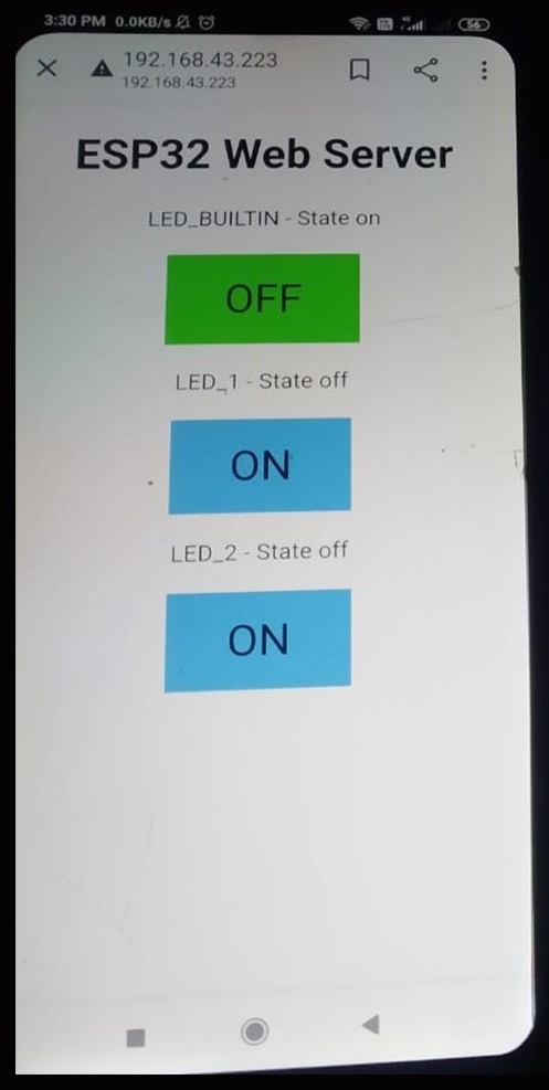
- Now the question arises, how will ESP32 understand which Button has been pressed?
- For that, we have created multiple links i.e. the HomePage Url will look like:
http://192.168.43.188/
- When a user will click on LED 26 ON Button, we will redirect the user to:
http://192.168.43.188/26/on
- Now, when the client wants to turn OFF the LED, we will redirect to:
http://192.168.43.188/26/off
- So, actually, we are checking the request from the client and based on that request we are turning ON or OFF the respective LED.
- Moreover, we are providing the same webpage to all the links but with the change in the state of each button i.e. if it's ON then Blue, otherwise Green.
If it looks too complicated, don't worry. These things will get more clear when we will cover the Arduino coding.
Note:- If you are not familiar with the basics of the esp32 module, then go through the previous tutorial, which is the Introduction to the ESP32 Programming Series.
ESP32 server Modes:
ESP32 Wi-Fi module includes a number of useful characteristics, including the ability to use a soft access point mode, a station mode, or both modes at the same time. Only station mode will be discussed in this session. I'll also cover how to use this board in soft access mode in future tutorials.
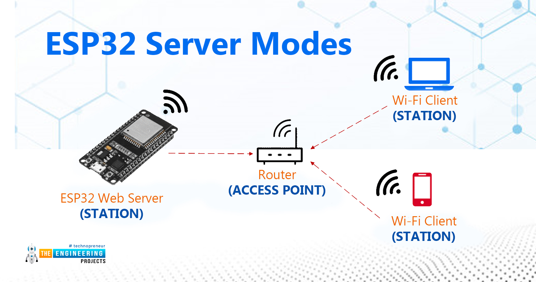
- Station Mode: The ESP32 board connects to your Wi-Fi network via a router in Station mode. The router serves as the communication channel between the web client and the ESP32. The IP address is obtained from the Wi-Fi router. Web clients can connect to the Web server using this IP address across a local network.
- Access Point Mode: In this mode, the ESP32 creates its own wireless Wi-Fi network, similar to the one provided by your existing router. We don't need to connect the ESP2 to a Wi-Fi network in this mode. This Wi-Fi board can link up to 5 devices to the Wifi network it creates.
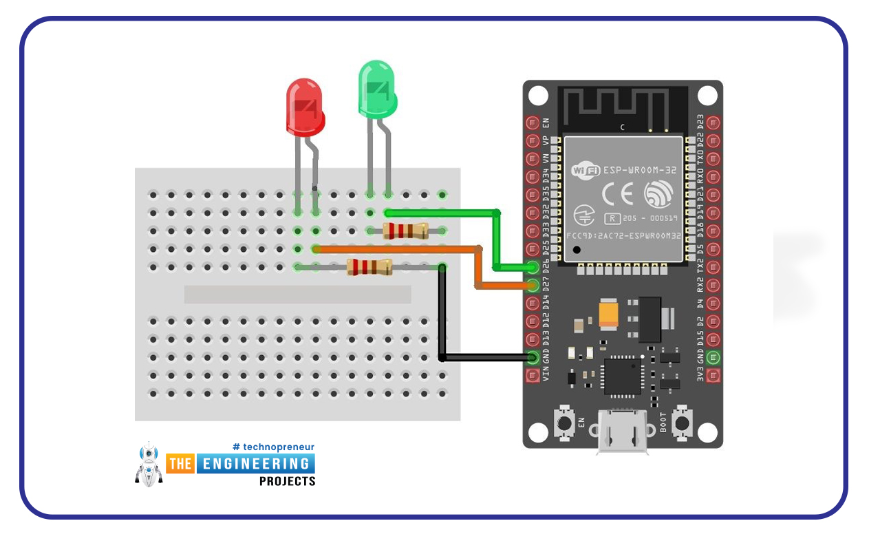
Connect the peripherals to the ESP32 board which you want to control through the ESP32 Web Server.
Here, we are going to control two external LEDs connected to LED1 (GPIO 26), LED2 (GPIO 27), and an inbuilt LED.
The following are the requirements for creating an ESP32 webserver to control peripherals:- ESP32 module
- Internet connection
- LEDs
- Resistors
- Connecting Wires
Arduino IDE Code
- Using the Arduino IDE, upload the following code to the ESP32 module:
#includeNote:// Replace with your network credentials char* ssid = "ESP32"; //enter SSID char* passphrase = "asdfgf@123"; // enter the password // Set web server port number to 80 WiFiServer server(80); // Variable to store the HTTP request String header; // Auxiliar variables to store the current output state String output26State = "off"; String output27State = "off"; String builtin_led_state = "off"; // Assign output variables to GPIO pins const int output26 = 26; const int output27 = 27; // Current time unsigned long currentTime = millis(); // Previous time unsigned long previousTime = 0; // Define timeout time in milliseconds (example: 2000ms = 2s) const long timeoutTime = 2000; void setup() { Serial.begin(115200); // Initialize the output variables as outputs pinMode(output26, OUTPUT); pinMode(output27, OUTPUT); pinMode(LED_BUILTIN, OUTPUT); // Set outputs to LOW digitalWrite(output26, LOW); digitalWrite(output27, LOW); digitalWrite(LED_BUILTIN, LOW); // Connect to Wi-Fi network with SSID and password Serial.print("Connecting to "); Serial.println(ssid); WiFi.begin(ssid, passphrase); while (WiFi.status() != WL_CONNECTED) { delay(500); Serial.print("."); } // Print local IP address and start web server Serial.println(""); Serial.println("WiFi connected."); Serial.println("IP address: "); Serial.println(WiFi.localIP()); server.begin(); } void loop(){ WiFiClient client = server.available(); // Listen for incoming clients if (client) { // If a new client connects, currentTime = millis(); previousTime = currentTime; Serial.println("New Client."); // print a message out in the serial port String currentLine = ""; // make a String to hold incoming data from the client while (client.connected() && currentTime - previousTime <= timeoutTime) { // loop while the client's connected currentTime = millis(); if (client.available()) { // if there's bytes to read from the client, char c = client.read(); // read a byte, then Serial.write(c); // print it out the serial monitor header += c; if (c == '\n') { // if the byte is a newline character // if the current line is blank, you got two newline characters in a row. // that's the end of the client HTTP request, so send a response: if (currentLine.length() == 0) { // HTTP headers always start with a response code (e.g. HTTP/1.1 200 OK) // and a content-type so the client knows what's coming, then a blank line: client.println("HTTP/1.1 200 OK"); client.println("Content-type:text/html"); client.println("Connection: close"); client.println(); // turns the GPIOs on and off if (header.indexOf("GET /26/on") >= 0) { Serial.println("GPIO 26 on"); output26State = "on"; digitalWrite(output26, HIGH); } else if (header.indexOf("GET /26/off") >= 0) { Serial.println("GPIO 26 off"); output26State = "off"; digitalWrite(output26, LOW); } else if (header.indexOf("GET /27/on") >= 0) { Serial.println("GPIO 27 on"); output27State = "on"; digitalWrite(output27, HIGH); } else if (header.indexOf("GET /27/off") >= 0) { Serial.println("GPIO 27 off"); output27State = "off"; digitalWrite(output27, LOW); } else if (header.indexOf("GET /LED_BUILTIN/on") >= 0) { Serial.println("BUILTIN LED on"); builtin_led_state = "on"; digitalWrite(LED_BUILTIN, HIGH); } else if (header.indexOf("GET /LED_BUILTIN/off") >= 0) { Serial.println("BUILTIN_LED off"); builtin_led_state = "off"; digitalWrite(LED_BUILTIN, LOW); } // Display the HTML web page client.println(""); client.println(""); client.println(""); // CSS to style the on/off buttons // Feel free to change the background-color and font-size attributes to fit your preferences client.println(""); // Web Page Heading client.println(" ESP32 Web Server
"); // Display current state, and ON/OFF buttons for builtin led client.println("LED_BUILTIN - State " + builtin_led_state + "
"); // If the LED is off, it displays the ON button if (builtin_led_state=="off") { client.println(""); } else { client.println(""); } // Display current state, and ON/OFF buttons for GPIO 26 client.println("LED_1 - State " + output26State + "
"); // If the output26State is off, it displays the ON button if (output26State=="off") { client.println(""); } else { client.println(""); } // Display current state, and ON/OFF buttons for GPIO 27 client.println("LED_2 - State " + output27State + "
"); // If the output27State is off, it displays the ON button if (output27State=="off") { client.println(""); } else { client.println(""); } client.println(""); // The HTTP response ends with another blank line client.println(); // Break out of the while loop break; } else { // if you got a newline, then clear currentLine currentLine = ""; } } else if (c != '\r') { // if you got anything else but a carriage return character, currentLine += c; // add it to the end of the currentLine } } } // Clear the header variable header = ""; // Close the connection client.stop(); Serial.println("Client disconnected."); Serial.println(""); } }
- You need to modify the SSID and password with your network credentials.
Code Description:
Here, we'll take a closer look at the code to see how it works.
- The first task is to add a Wi-Fi library.
- As mentioned previously, you must type your SSID and password inside the double quotes in the following lines.

- As we are creating a web server, so we need to assign a port to it and normally we use port 80 for a local webserver.
- So, in the below code, Port 80 is assigned to the webserver and then initialized a few variables:
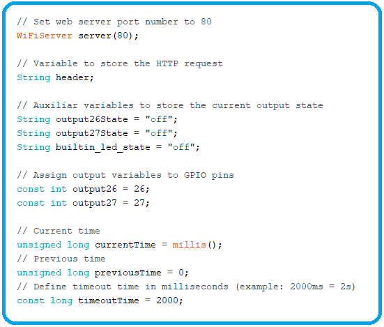
- String header: variable to store the header of the HTTP request.
- Below the header variable, we have variables to store the current state of connected peripheral LEDs and built-in LED. If you wish to add more peripherals and save their states, you need to create more variables. By default, all LEDs are in the OFF state.
- Next, assigned GPIOs to each peripheral device or component. Here we are using GPIO 26(LED1) and GPIO 27(LED2). You can use any other suitable GPIOs.
- Lastly, we have initialized a few variables to check the connection timeout, we will check their working soon.
Arduino Setup() Function
- Now let's first have a look at the Arduino setup loop.
- First, we have initialized our Serial Port at a baud rate of 115200, so that we could monitor the results at the serial terminal.
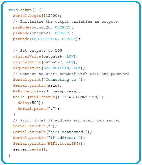
- Define the GPIOs as OUTPUTs and set them to LOW, as by default LEDs will be off.
- To set up a wifi connection, we called the WiFI.begin() and here we have provided our SSID and passphrase as variables.
- Now our ESP32 will try to connect to the provided WiFi connection.
- As you can see, we have a while loop, where we are checking the WiFi Status.
- If ESP32 gets connected with WiFi, the while loop will break and a message will get printed on the Serial Monitor "WiFi Connected".
- Now our ESP32 is connected to the WiFi, so the router must have assigned an IP address to ESP32 and we are printing it on Serial using WiFi local IP Function.
- Finally, we begin our server, to which we have assigned Port 80 at the start.
Arduino Loop() Function
Now, we are done with all the basic settings in the setup function. Let's have a look at the code in the Loop function:
- At the last line of the Setup function, we have started our webserver, so now ESP32 is acting as a webserver and is waiting for incoming clients.
- But what will happen, when someone will hit the IP Address of this webserver?
- So, in the loop function, first of all, we are listening to the incoming client using the server.available() function.
- If any client is available i.e. someone has entered our IP Address in the browser then we will print the HTML page.

- So, we are going to write the rest of our code in this IF loop.
- AS you can see in the below code, if the client is available, we have printed "New Client" on Serial Monitor.
- After that, we have a while loop checking for client connection, so as long as we have a connection with the client, we will remain in this loop.
- Inside this while loop, we have an If loop, checking if the client is available.
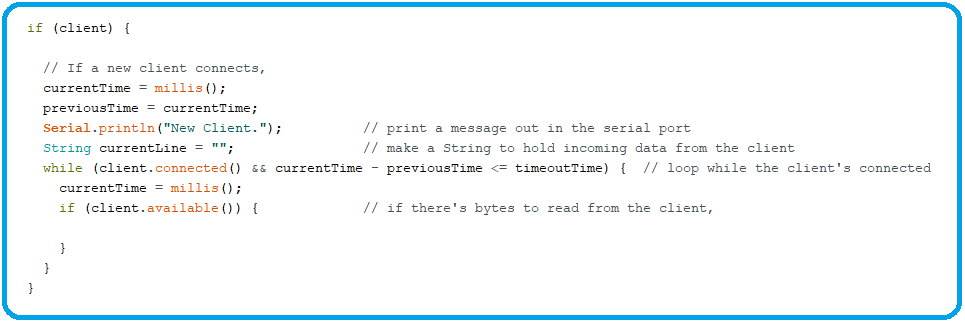
- Now, if we are connected to the client, we need to read for the incoming request.
- So, If there are any bytes to read from the client, read those bytes:
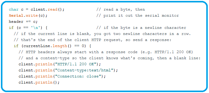
- The client request ends at New Line Character \n, so we are checking for that.
- Once we received the New Line Character, we are sending the response back to the Client.
- In response, we have first sent the HTTP header, which is the default for webpages so that browsers should understand the response type.
Checking Request Type
- As we discussed earlier, on each button press, we are redirecting our client to its respective link.
- Depending on which button is pushed, we make requests to different URLs to turn the LEDs on and off using if else statements, as shown below:
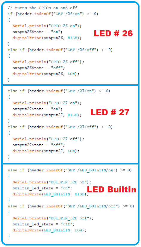
- As you can see in the above code, we are repeating the same code three times for 3 LEDs.
- In the first block, we are simply checking the header response and if it's a GET request and from "/26/on", we have turned that Pin HIGH, changed the LED state variable to "on" and sent a message on the serial monitor.
- So, if a client clicks on the LED 26 ON button, ESP32 will understand the GET request and glow the LED.
- The other buttons work in the same way. If you wish to add more outputs, you'll need to change this section of the code.
HTML to display a web page
- We have designed the output part i.e. what we are going to do when a user clicks any button.
- And now we are going to design those buttons themselves i.e. we are designing the webpage.
- As you can see in the below figure, we have standard HTML tags at the start.
- After that, we have some CSS text to design the buttons and the appearance of the web page. We use the Helvetica font and set the information to be shown as a block with the center aligned.
- Next, displaying Web page heading i.e. "ESP32 Web Server".
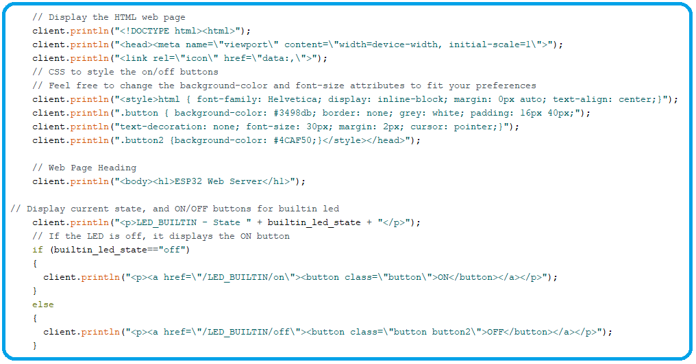
- Next, comes the If Loop for the first Button, we are checking the LED state variable and based on LED state, we are displaying our Button.
- So, if the LED state is OFF, we are redirecting the user to /LED_BUILTIN/on and vice versa.
- That's how we are changing the Buttons on the webpage, as you can see buttons are using different CSS classes for on and off states.
- Similar loops are used to display the states on other connected LEDs.
- Finally, we are closing the web connection and clearing the header that was used to store the HTTP request header using client.stop() function.
- Printing information about the closed web connection on the serial monitor.
Uploading Web Server Code to ESP32
- Please reread the previous instruction, "Introduction to ESP32 programming series," if you are unfamiliar with the procedure of uploading code in the Arduino IDE.
- After uploading the code, open the Serial Monitor with a baud rate of 115200.
- Enable the ESP32 by pressing the EN (enable) button. The ESP32 establishes a Wi-Fi connection and the Serial Monitor displays the ESP32 IP address. To connect to the ESP32 web server, you'll need that IP address.
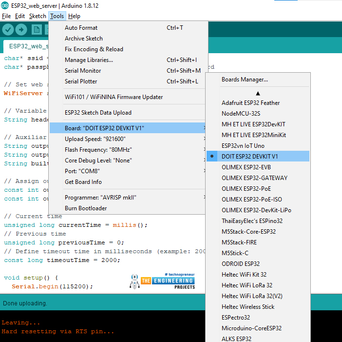
- Make sure you have selected the right board and COM port.
Getting IP address and Access ESP32 web Server
- After successfully uploading the code in esp32 module.
- Open Serial Monitor from the top right corner of Arduino IDE screen as shown in figure below:
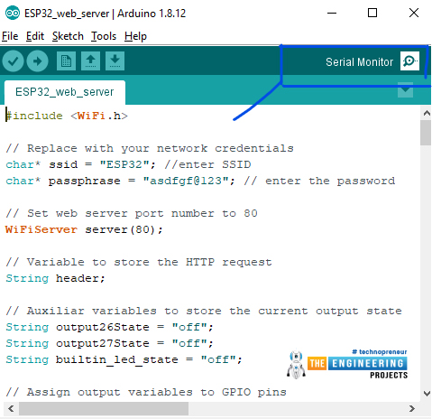
- The IP address required to connect to the ESP32 point will be displayed on the Serial Monitor. It's 192.168.43.223 in this scenario.
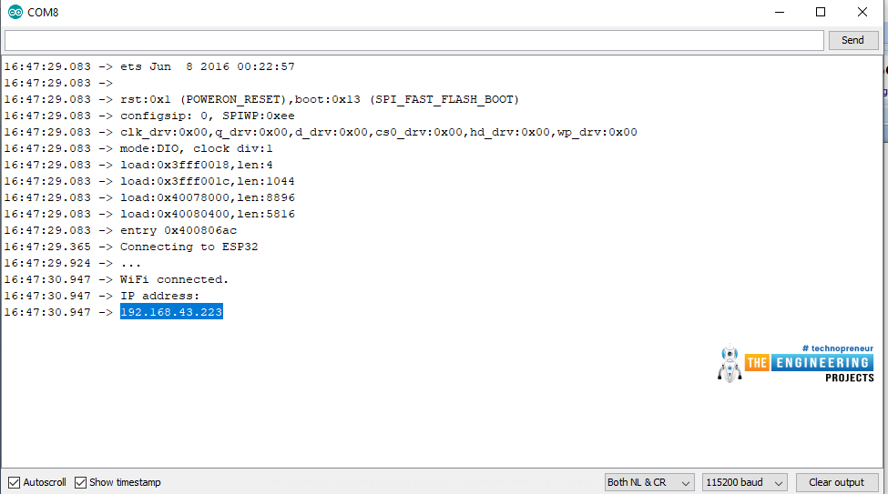
- To access the webserver, type the IP Address of the ESP32 into a Web Browser on a laptop or a mobile phone. It's 192.168.43.223 in our case.
- You should be able to see a simple web page served by the ESP32's Web Server if everything goes well.
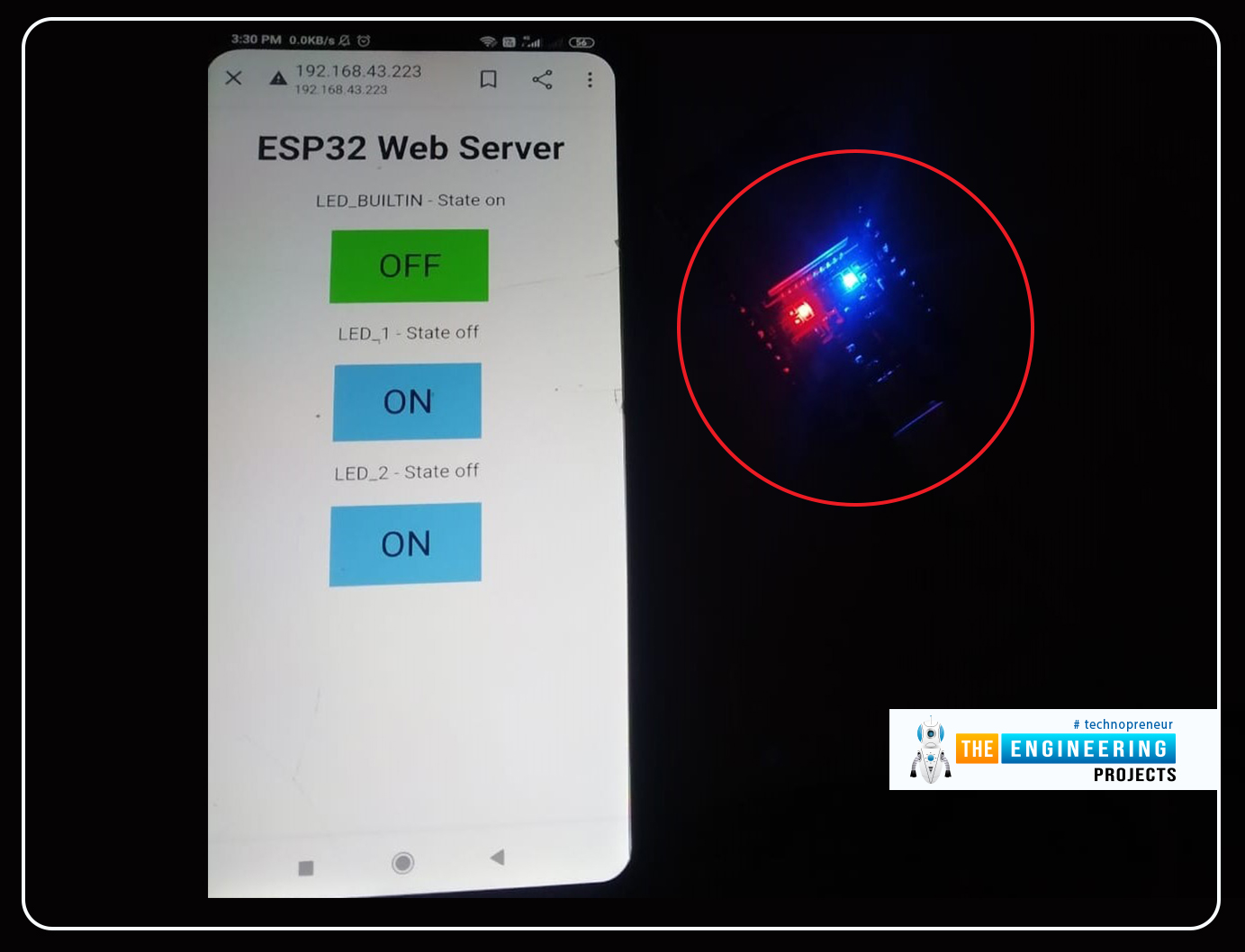
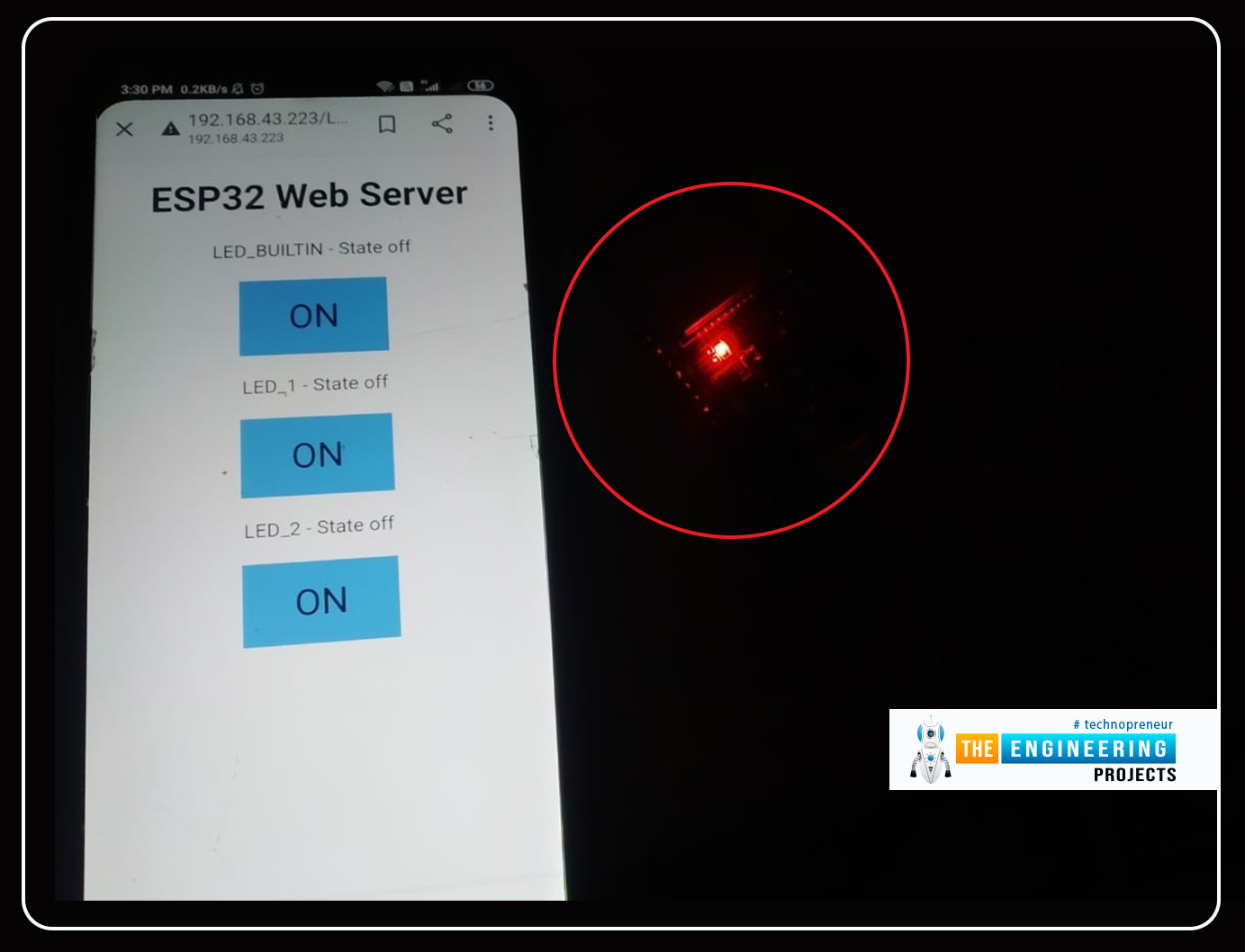
A screenshot of a Web Browser on a laptop accessing the ESP32 Web Server is shown below.
- The image below is displaying the ON state of the inbuilt LED.
- The inbuilt LED is Blue in color.
- The below image is displaying the OFF State of the inbuilt LED
Hence, We have done a lot of work on the ESP32 by using it as a server. In the beginning, we saw what is a web server and studied its features in detail. After that, we saw that ESP32 can be used as a server and we saw the feature that makes it ideal for this task. Then we experimented to learn the concept, in which we saw the built-in example of ESP32 as a server in Arduino IDE. We saw the step-by-step procedure to experiment and once it was completed, we moved on to a more complex example. I hope you find this tutorial useful and have performed it by yourself but if you are stuck at any point, you can ask in the comment section.
Using the ESP32 web server and the preceding process, you can control the peripherals linked to the ESP32 module from any mobile, tablet, or computer. The only need is that all of the devices to be linked to the same network.
This concludes the lesson. I hope it becomes useful to you. In the next tutorial, we will have a look at How to work the ESP32 BLE, so stay tuned. Have a good day. :)


