The two most significant hazards to the agriculture industry are the need for extensive labor and a scarcity of water. According to the World Wildlife Fund (WWF) organization, water shortages might affect two-thirds of the world's population by 2025, putting both the ecosystem and human health at risk. The use of automatic plant watering systems eliminates both of these problems by watering plants at specified times and amounts while monitoring their hydration levels through measuring moisture in the soil surrounding the plants. Automatic plant watering systems can be used in homemade gardens and can also be deployed in fields for large-scale use. Whenever designing an automatic watering system, it is important to keep in mind that the system should be expandable, allowing for the simple integration of new devices in order to broaden the applicability of the system.
| Where To Buy? | ||||
|---|---|---|---|---|
| No. | Components | Distributor | Link To Buy | |
| 1 | Buzzer | Amazon | Buy Now | |
| 2 | LEDs | Amazon | Buy Now | |
| 3 | DS1307 | Amazon | Buy Now | |
| 4 | LCD 20x4 | Amazon | Buy Now | |
| 5 | Arduino Uno | Amazon | Buy Now | |
Software to Install
We are not designing this project using real components, instead, we are going to design its Proteus simulation. So, first of all, you should Install Proteus Software itself. Proteus software has a big database of electronics components but it doesn't have modules in it. So, we need to install Proteus Libraries of a few components, so that we could simulate them. So, these are the PRoteus libraries which you should install first, before working on this project:- Arduino Library for Proteus: Adds Arduino boards to Proteus components list.
- LCD Library for Proteus: Adds LCD module in Proteus Suite.
- Water Sensor Library for Proteus: Add Water Sensor in Proteus components list.
- DS1307 Library for Proteus: Adds RTC module DS1307 in Proteus Environment.
- Soil Moisture Sensor Library for Proteus: Adds Soil Moisture Sensor in Proteus software.
- Latest Proteus Libraries for Engineering Students V2.0.
- Proteus Libraries of Digital Sensors.
- Proteus Libraries of Embedded Sensors.
- New Proteus Libraries for Engineering Students.
Project Overview:
Three main components of an autonomous watering system are:
- Water Level Sensor: monitors the water reservoir level.
- Moisture Sensor: monitors the soil moisture level.
- RTC module: responsible for supplying water to the plant at predetermined intervals or at a predetermined time.
- Arduino UNO: serves as a hub for connecting and controlling all these components.
It is necessary to integrate the water level sensor with the microcontroller before it can be installed within the water reservoir. The location of the water level sensor within the reservoir is variable and is determined by the user and the application for which it is being utilized. The Arduino receives continuous data from the water level sensor and warns the user when the water goes below a certain level, either by an alarm or a buzzer, as appropriate.
The soil moisture sensor operates in a manner similar to that of the water level sensor. The tip of the sensor is inserted into the soil near the plant, and the sensor is activated. In the case of a moisture sensor, the closeness of the sensor to the plant is also variable, and the user may adjust it depending on the features of the plant for which it is being used. In vast agricultural fields, a single sensor may be used for numerous plants if they are closely spaced and their hydration levels can be determined by measuring the soil moisture at one location that overlaps with another spot on the soil surface.
The RTC module operates on the same concept of time monitoring in the background as other electronic devices such as computers and smartphones; even when these devices appear to be turned off, they continue to keep track of the current time. The RTC module, on the other hand, is capable of exchanging time information with the Arduino board. On a specific day of the week, at a specific time of day, the Arduino is pre-programmed to turn on the water pump and turn off the water pump after a specified length of time.
Components Needed:
- Arduino UNO
- Water Level Sensor
- Moisture Sensor
- RTC Module (DS1307)
- LCD
- 4 LEDs
- Buzzer
- Relay
- Water Pump
- PCF8574
Component Details:
Arduino UNO:
- Arduino UNO is a programmable microcontroller board.
- It contains Atmel's ATMega328 as is based on that microcontroller.
- The Arduino board also contains an in-built voltage regulator to protect it from burning out and supports serial communication to help programmers.
- The Arduino board is culturally programmed through the Arduino App designed by the board's developers and the programming is done in C language.
- The Arduino App compiles code and interfaces the firmware into the Arduino hardware.
- Arduino UNO has 14 digital I/O pins out of which 6 are PWM pins as well.
- Arduino also takes analog inputs and has 6 analog input pins.

Figure # 1: Arduino UNO
Soil Moisture Sensor:
- The soil moisture sensor is a resistive sensor that consists of two electrodes with a small charge and the resistance in those electrodes is measured and then the resistance in between the soil is used to find the moisture levels.
- A soil moisture sensor normally comes equipped with an amplifier such as LM393. It has a VCC, GND and analog output pin.
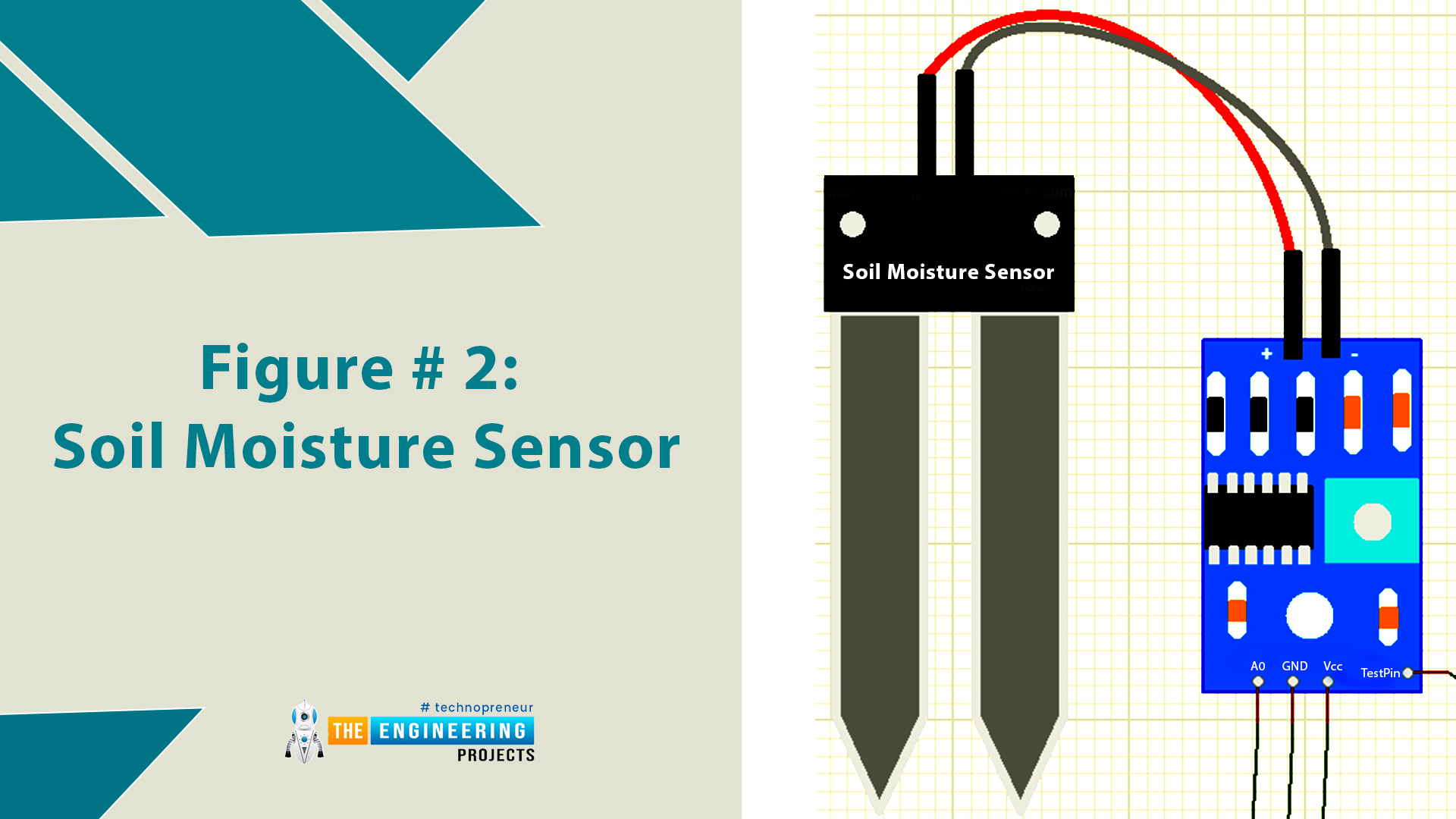
Figure # 2: Soil Moisture Sensor
Water Level Sensor:
- The water level sensor is a module that helps calculate the amount of liquid in a container.
- When a liquid is present in the tank, the Submersible level sensor detects the hydrostatic pressure generated by the liquid.
- Since hydrostatic pressure is a measure of two variables, the first of which is the density of the fluid and the second of which is the height of the fluid, it is a useful tool.
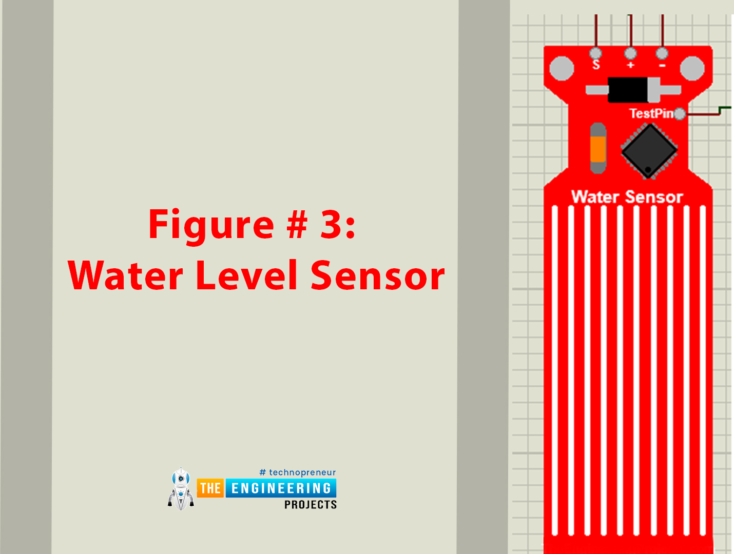
Figure # 3: Water Level Sensor
RTC Module:
- RTC stands for real Time Clock and as the name suggests the module keeps track of time even when the external power supply is cut off.
- It has a battery cell installed within it for that purpose, moreover, it is capable of communication with other devices such as Arduino too.

Figure # 4: RTC Module
Relay:
- Relays are basically electrical or electromechanical switches that operate on the principle of magnetic field controlling the switching within the relay.
- A relay has two modes of operation, normally open and normally closed.

Figure # 5: 12V Relay
PCF8574:
- The PCF8574 is a silicon-based CMOS integrated circuit.
- Using the two-line bidirectional bus enables general-purpose remote I/O extension for the majority of microcontroller families (I2C).
- It is used in our project for I2C communication of LCD.

Figure # 6: PCF 8574
Proteus Simulation of Plant Watering System
Now, let's design the Proteus Simulation of Plant Watering System first and then will work on the Arduino Code.- First of all, make sure that Proteus is installed on your computer and download all the necessary libraries for Proteus beforehand.
- For this project, you will need libraries for Arduino, LCD, RTC Module, Water Level Sensor and Soil Moisture Sensor. Make sure that you read how to use each library in Proteus as well.
- Open a new project on Proteus, import all the components required and place them within the working area or the blue line of Proteus.
- Select below components from Proteus Components' library:
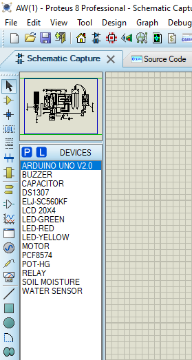
Circuit Diagram and Working:
- Now, place these components in your Proteus workspace, as shown in the below figure:
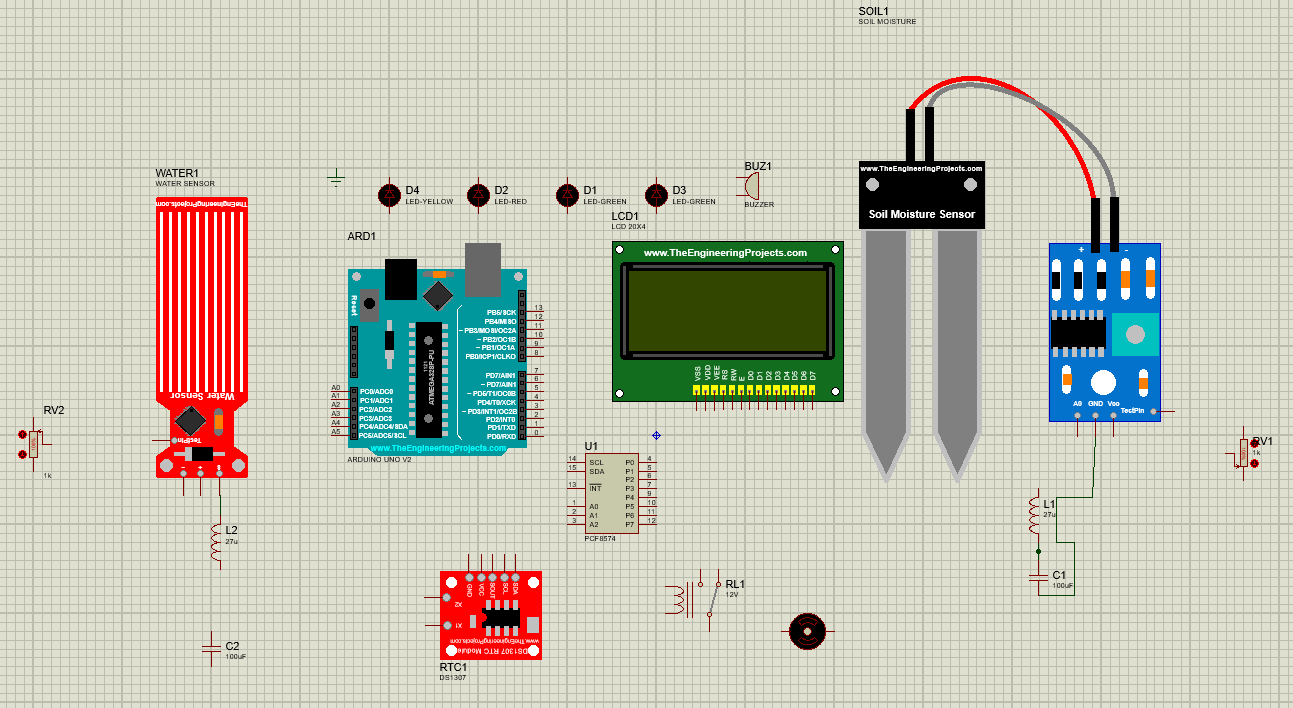
- For the water level and moisture sensor, place a variable POT(potentiometer) at the test pin and place an RC filter at the output pins. (This is only for simulation purposes)
- Start with the input side of Arduino and connect the soil moisture, water level output pins to the A1 and A0 pins of Arduino respectively.
- To use the LCD for I2C communication, Place PCF8574 and connect with LCD.
- Connect the SDA and SCL pins of PCF8574 and the SDA and SCL pins of the RTC module with the SDA and SCL pins of Arduino.
- For the output side of Arduino, Connect the D7 to the relay controlling the pump.
- Connect the buzzer at D2 and the LEDs to their respective Arduino pins as well.
- Make sure appropriate power and ground are provided to each component. With that the making of the circuit on Proteus is complete.
Figure 7 shows the circuit diagram of the system. Proteus was used to simulate the circuit and Arduino App was used for the simulation of the Arduino code. The circuit was designed in a way that is easy to understand and further integrated easily. We will now go through a step-by-step guide on how the circuit was built.
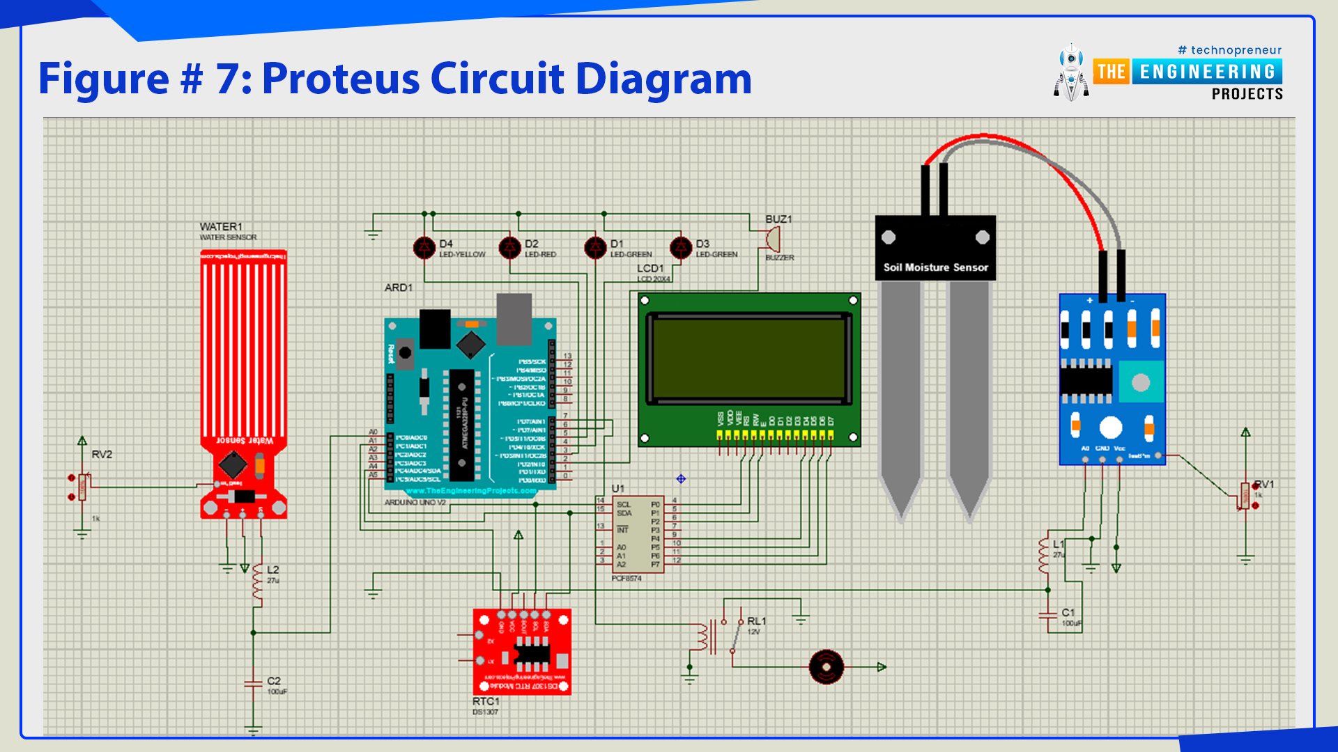
Figure # 7: Proteus Circuit diagram
Arduino Code for Plant Watering System
A normal Arduino code has two main segments:
- void setup
- void loop
Declaration Code
- The first step in setting up our code is defining libraries, download if you don’t have any libraries already integrated in the Arduino App.

Figure # 12: Arduino Code
- The next step in the code is tone definition for buzzer and pin definition of variables being used in the project.
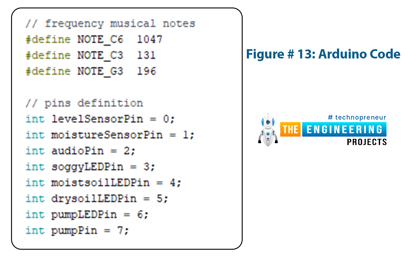
Figure # 13: Arduino Code
- After pin definition, the variables used must be defined so that Arduino knows where to find them and how to identify them.
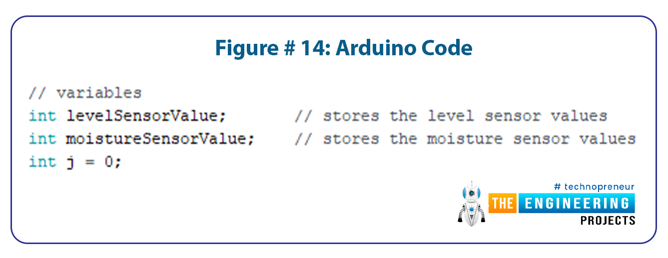
Figure # 14: Arduino Code
- The next step is defining the system messages that will appear on the LCD.
- It is not necessary to define those messages in the setup, they can be easily defined within the main code but it is an easier way to define those beforehand and call them whenever needed.
- This is especially useful when a system message is used multiple times in the code.
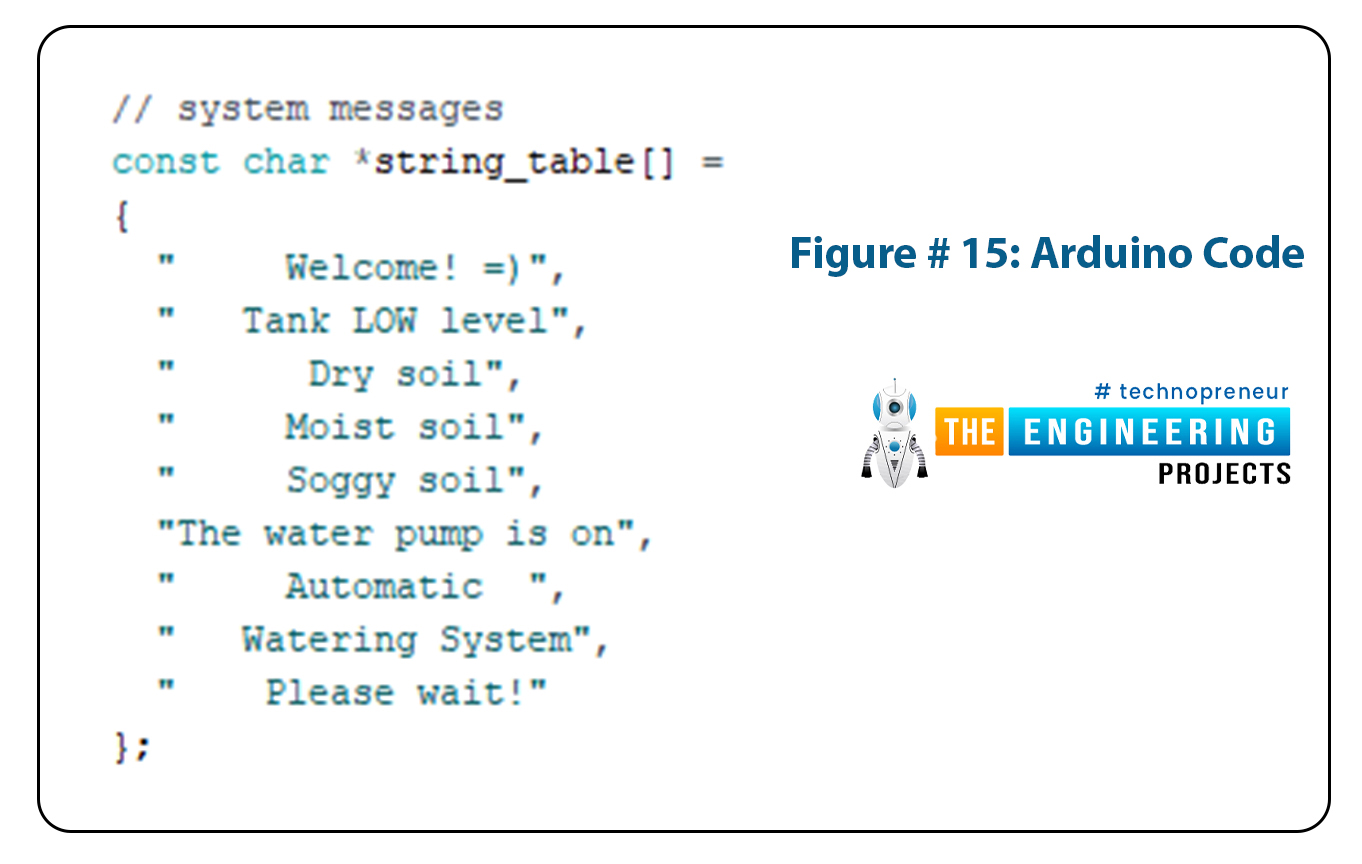
Figure # 15: Arduino Code
- Now we define the objects being used in the project.
- The two objects being defined are the RTC module and LCD. In the syntax below we used 20x0 in the argument for the LCD, that is because there are no libraries for I2C LCDs and we had to turn a simple LCD into an I2C LCD by the means of PCF8574.

Figure # 16: Arduino Code
Void setup:
Now we start the programming of void setup.- At first is the initialization of various components, such as initializing the RTC module and setting the time and date of RTC with respect to our computer.
- Wire initialization and library are used for I2C communication.
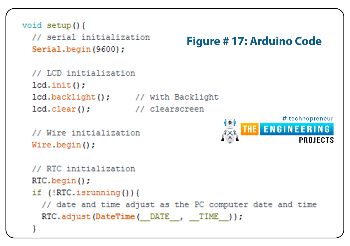
Figure # 17: Arduino Code
- The next step is defining the digital pins of Arduino being used as input or output pins and displaying the initial message on our LCD.
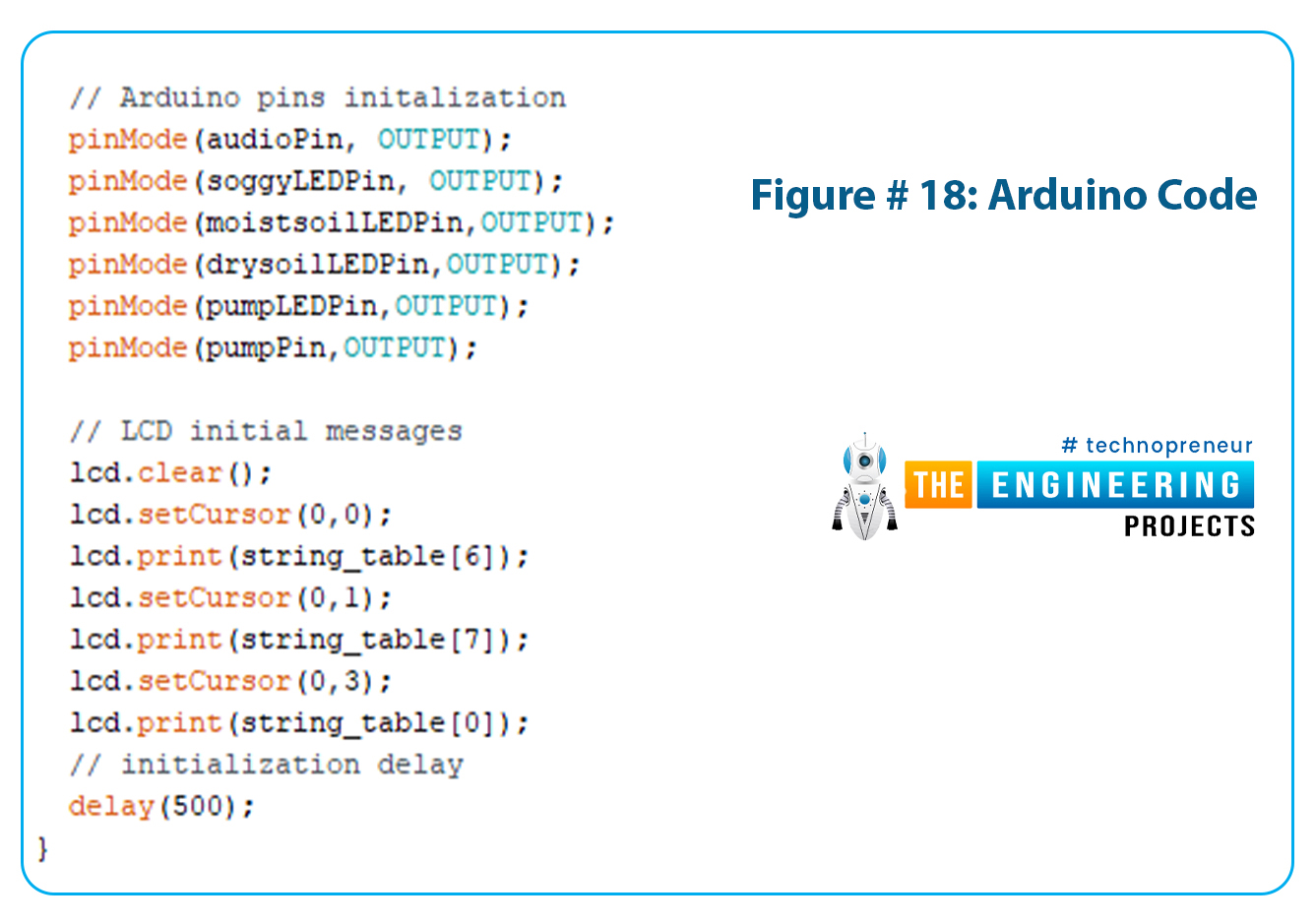
Figure # 18: Arduino Code
Void Loop:
- The first step in the loop is to read the date and time from the computer through the RTC and read the values from the sensor.
- Since this part of the program runs in the loop, Arduino will keep reading and refreshing the sensor inputs every time the loop starts.
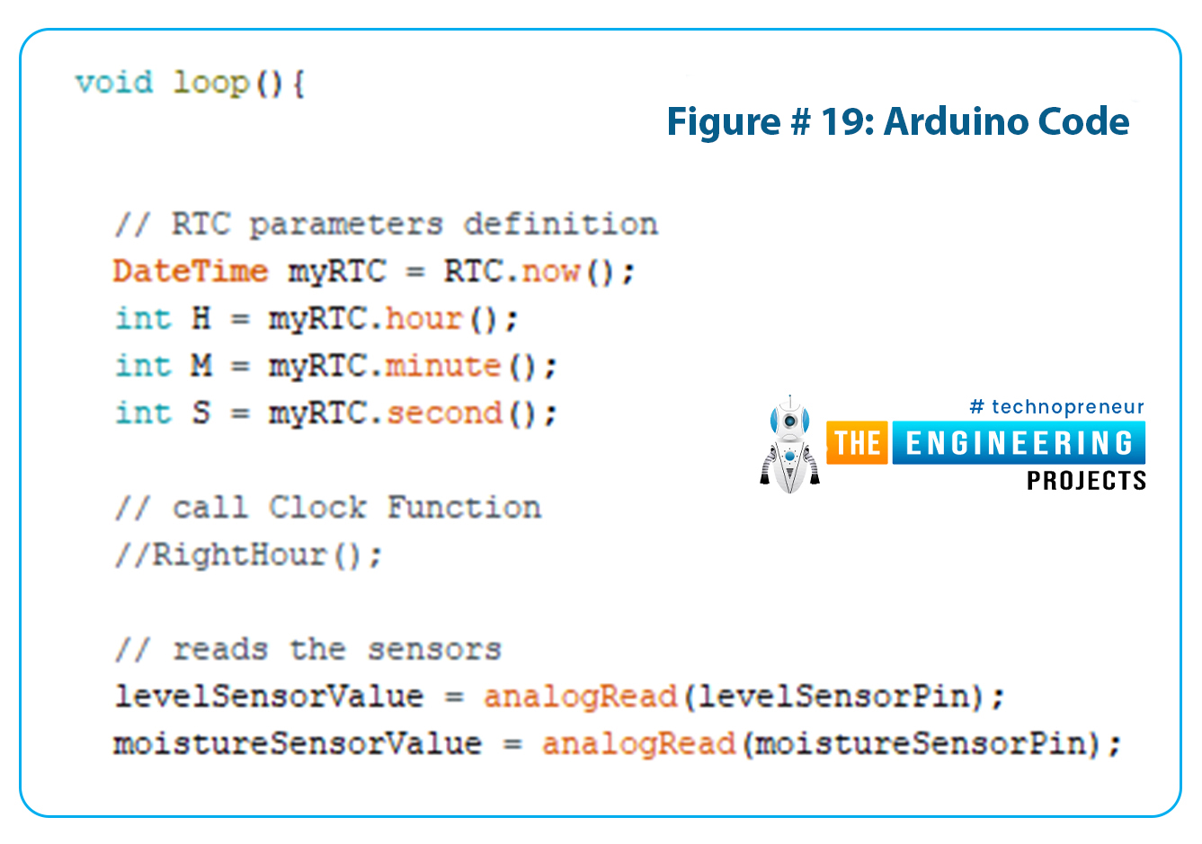
Figure # 19: Arduino Code
- In the next segment of the code, we will check various conditions of the sensor values and RTC and actuate our outputs on the basis of these conditions.
- At first, we check the water level of the container, if it is below the set level, Arduino will actuate the buzzer to alarm the user of low tank on LCD.

Figure # 20: Arduino Code
- In the next step, we check the values of the moisture sensor and place the conditions in three categories, namely, moist soil, soggy soil and dry soil.
- The Arduino will light up the respective LED whenever its condition is true. Red LED for dry soil, yellow LED for soggy soil and green LED for moist soil.
- The LCD will also display respective messages for each of those conditions.
- The following code is for the condition of dry soil.

Figure # 21: Arduino Code
- The following code is for the condition of moist soil.

Figure # 22: Arduino Code
- And finally the code for the condition of soggy soil.

Figure # 23: Arduino Code
- In the next step of the code, we check the condition of time, whether it is time to water the plants or not and the condition of the water reservoir to see its level as well.
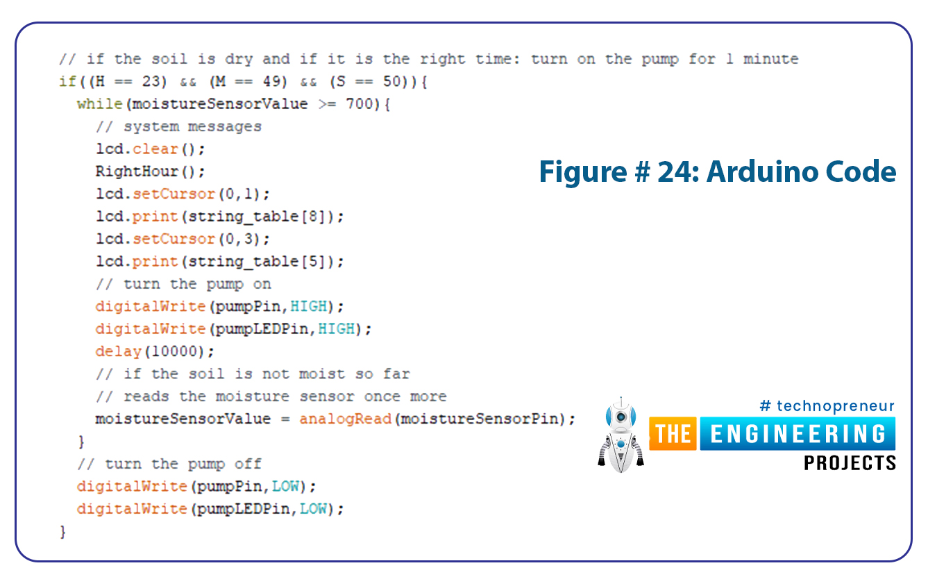
Figure # 24: Arduino Code
If you see the code closely, you may see the function of the right hour, which is called various times in the main code. The function code in itself is written at the bottom of the main code. This function is used for displaying the time and date on the LCD and also for fixing the date and time.
Results/Working
- Open Arduino and generate a hex file for that program.
- Put the hex file in the Arduino UNO board placed in Proteus.
- Run the simulation.
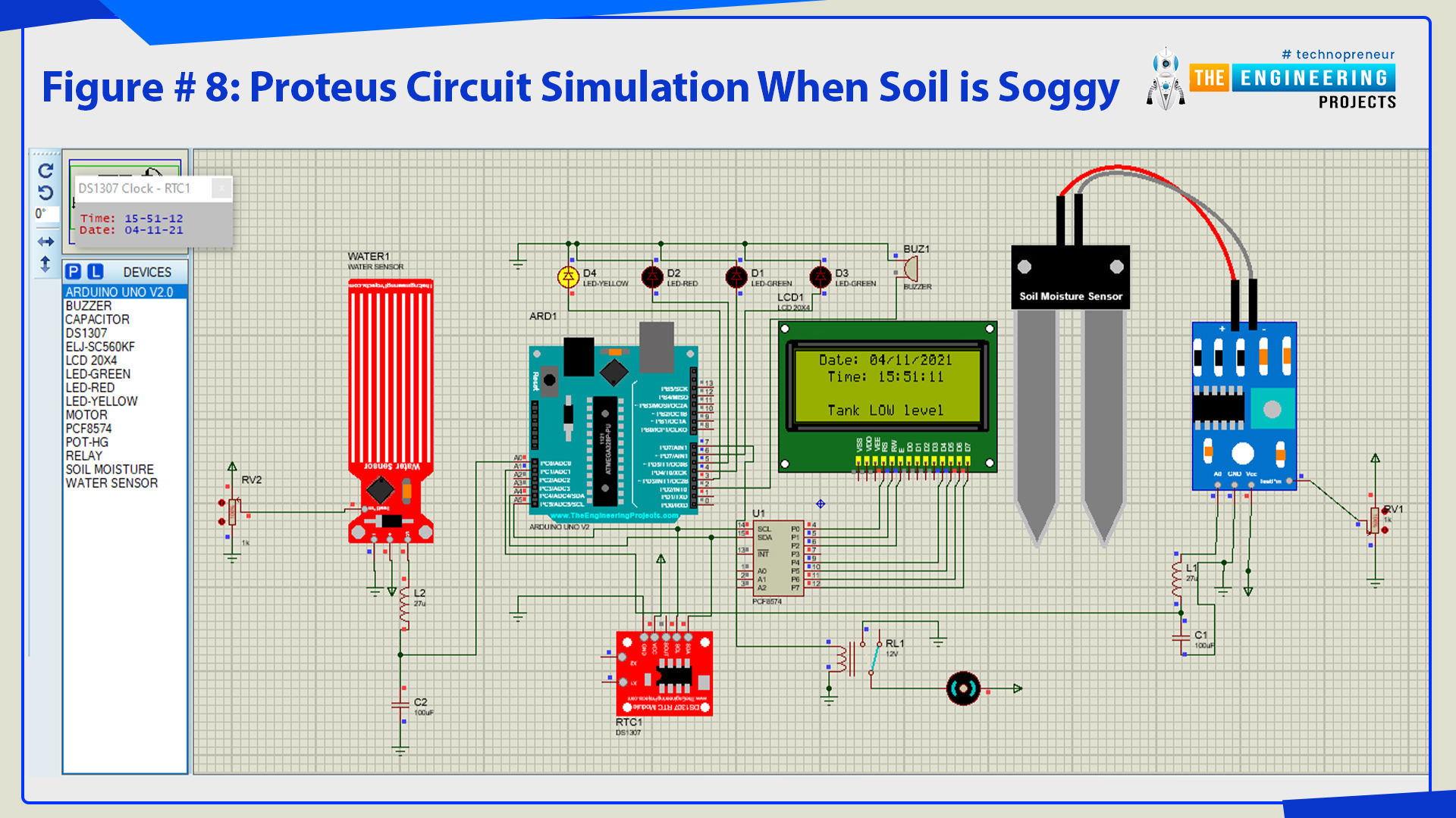
Figure # 8: Proteus circuit simulation when soil is soggy
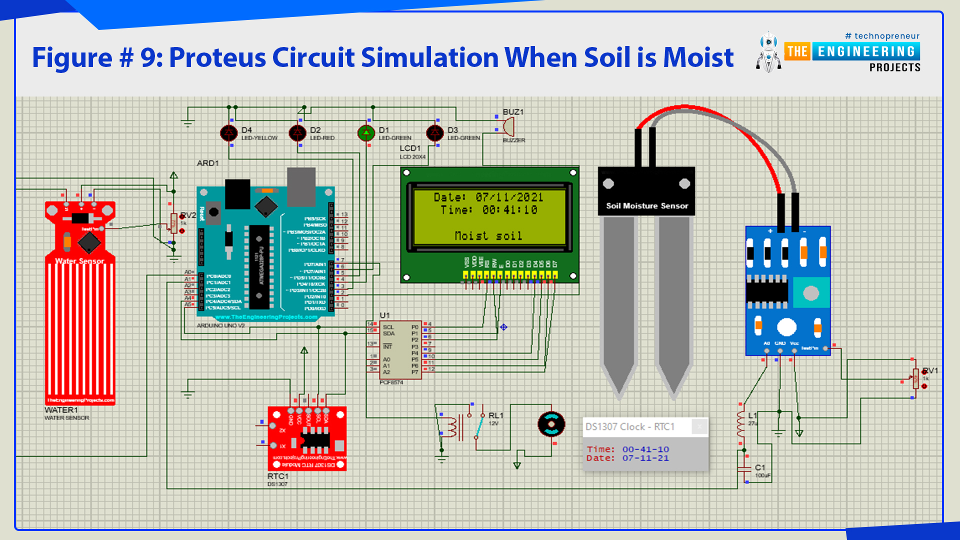
Figure # 9: Proteus circuit simulation when soil is moist
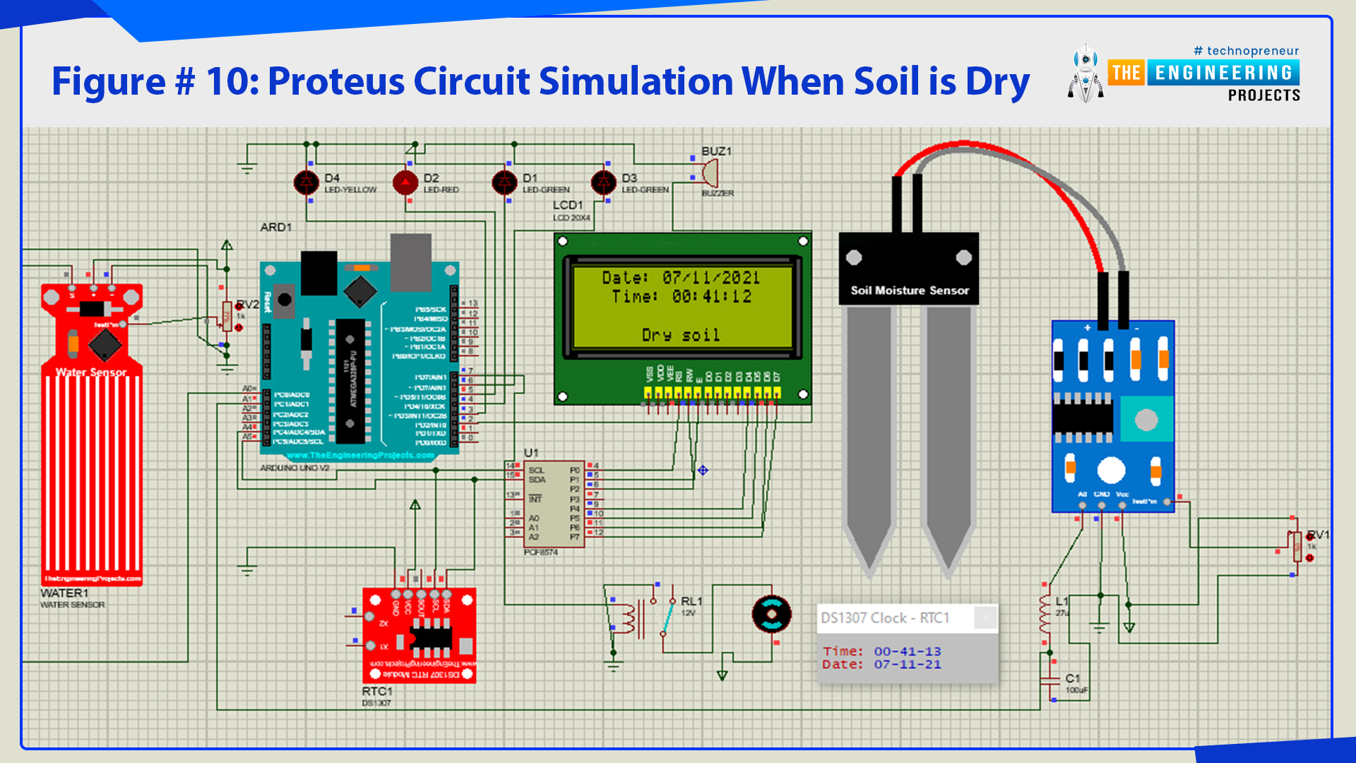
Figure # 10: Proteus circuit simulation when soil is dry

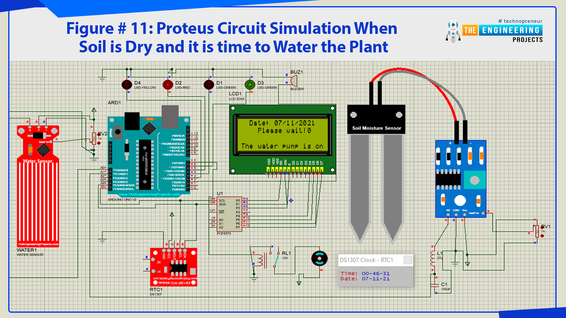
Figure # 11: Proteus circuit simulation when soil is dry and it is time to water the plant
As you can see from figure 8 that our simulation is running according to the program set at Arduino. You can increase or decrease the values coming from the sensors through the Potentiometer. So, that was all for today. I hope you have enjoyed today's lecture. If you have any questions, please ask in the comments. Thanks for reading.


