| Where To Buy? | ||||
|---|---|---|---|---|
| No. | Components | Distributor | Link To Buy | |
| 1 | ESP8266 | Amazon | Buy Now | |
Components Required
- 1x Computer/notebook with Arduino
- 1x Mini-USB cable.
- 1x NodeMCU (ESP8266 Breakout Board)
- Internet Browser (Chrome, Firefox, IE…)
ESP8266 Libraries for Arduino IDE
For this project, we will use two libraries:
- ESP8266WiFi: This library carries all the functions necessary for the ESP8266 to connect to a wifi network.
- ESPAsyncWebServer: This library carries the functions needed to create and manage an EB server.
Creating the code
- We can divide the code into three main functionalities:
- Control the LED.
- Connect to Wifi
- Create the webserver.
And we'll treat this building in blocks.
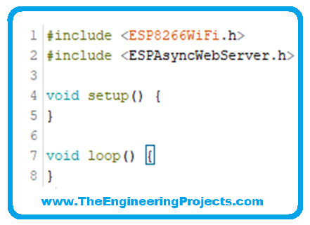
Importing Libraries
- The Libraries must be included at the beginning of the sketch so that their functions are already available elsewhere in the code.
LED Control with ESP8266
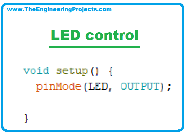
- Our first step is to define the pin to be used. For our example, we will use the LED of the NodeMCU module.

- And set this pin as output in the setup function.
- We will also create a variable to monitor LED status. This variable is not used to control the LED, but it will be important for the webserver so, we will include it here.

- So, we'll create a function that, whenever triggered, will change the state of the LED (and the variable).
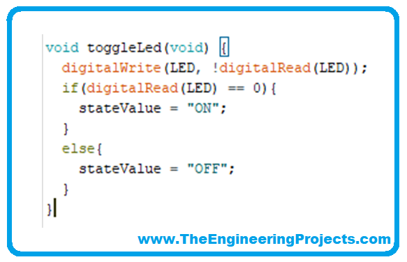
- The toggleLed() function makes a function nesting in its first line:
- The digitalWrite() function receives as a value for writing, the inverse of the reading of the pin itself. So each time the function is called, it reads the current value of the pin and toggles its value.
- The following conditional is only used to update the stateValue variable. To test the function, you can include it in the loop as follows:
- With these inclusions, we will have this code:
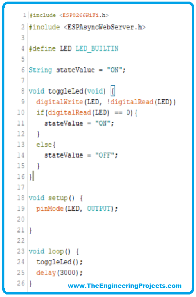
- With this code, the NodeMCU module LED, we expect to change state every 3 seconds. Remember to remove the data inside the loop function when you finish the test. We will not use them in the next steps.
Connect ESP8266 to WIFI
- Now let's connect the ESP8266 to your WIFI network. We'll start by creating a variable to store the network name and another one for the password.
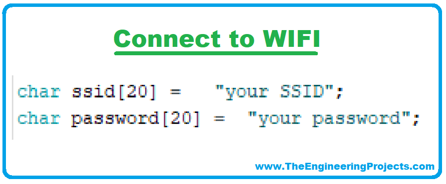
- The connection could be executed directly in the setup function, but we will create a standalone function to make the code more organized and so that it can be reused if you want to create a reconnect function.
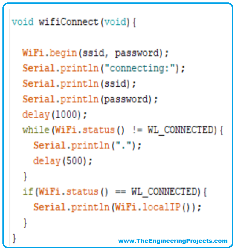
The wifiConnect() function will send a connection request and wait for it to be approved.
With Wifi.begin(), ESP8266 will search the network informed in the ssid variable and send a connection request, informing the password (just like what a cell phone would do).
The WiFi.status() function can return the following values:
- WL_CONNECTED: assigned when connected to a WiFi network;
- WL_NO_SHIELD: assigned when no WiFi shield is present;
- WL_IDLE_STATUS: it is a temporary status assigned when WiFi.begin() is called and remains active until the number of attempts expires (resulting in WL_CONNECT_FAILED) or a connection is established (resulting in WL_CONNECTED);
- WL_NO_SSID_AVAIL: assigned when no SSID are available;
- WL_SCAN_COMPLETED: assigned when the scan networks is completed;
- WL_CONNECT_FAILED: assigned when the connection fails for all the attempts;
- WL_CONNECTION_LOST: assigned when the connection is lost;
- WL_DISCONNECTED: assigned when disconnected from a network;
In this project, we are not handling connection failures, so we are only interested in the WL_CONNECTED return. The function will wait while this is not the connection status and, when identifying it, it will look for the IP address it received on the network.
Here is a point of attention. The WIFI network must allow the connection and provide an IP by DHCP. If any device can connect to your network just by offering the password, don't worry. This configuration must already exist.
We've added some information to be viewed on the Serial monitor, so the serial needs to be initialized before we call the wifiConnect() function.
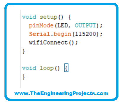
- This should be our code so far:

- The expected result on the Serial Monitor is as follows:
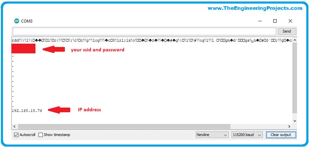
- From this point on, the ESP8266 can be found by network tools like the Advanced IP Scanner or a simple PING at the command prompt.
Creating the Webserver with ESP8266
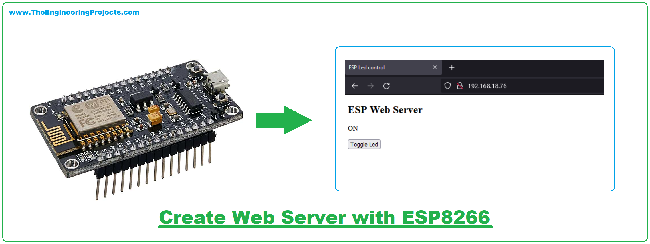
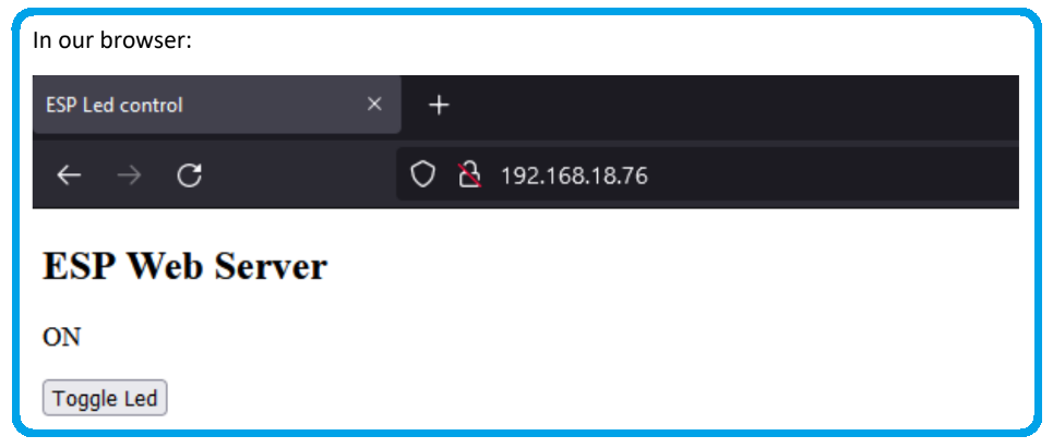
- Spoiler Alert: At the end of this step, you can view our webserver at the address
- HTTP://”IP address”, for our case http://192.168.18.76.
- We will start by creating an instance of AsyncWebServer operating on port 80.

- In short, a webserver operates as a file manager that delivers on-demand. Then the browser makes a request, the web server responds and continues to wait for new requests.
- All this happens following communication protocols (HTTP, FTTP, or both), rigorous error handling, and high-security logic.
- The library takes care of preparing the backstage of the webserver, which saves us a lot of time and lines of code. But we still need to configure what happens on each request.
We will handle two requests:
- When the page starts or refreshes
- When we press the LED state change
The first will occur when we send a GET request to the root “/”. What the browser does automatically when we go to http://192.168.18.76.

- The server will respond with status 200 (default success response), the information on the type of file sent ("text/html"), the HTML file (which we will create next and save in the variable index_html), and the return of the processor( ) (which we will also create now).
- The processor function simply returns the value of the updated stateValue variable.
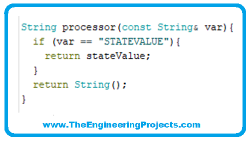
- The HTML file the browser expects tends to be large for a variable, and even with the good SRAM memory space the ESP8266 has, it could cause problems.
- That's why we'll use the PROGMEM utility so that the variable is written to FLASH memory.
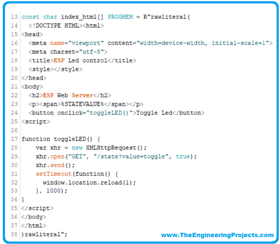
- Don't worry if you don't know HTML or javascript. We won't go into details, but we'll explain the most important ones for now.
- On line 23, the page displays the value returned by the processor() function.
- In line 24, the button calls the “toggleLED()” function when activated.
- The toggleLED() function makes a GET request at address “/state” passing the toggle valceue.

- After 1 second it refreshes the page to receive the updated value. We need to handle this request:
- When the server receives the request at the address “/state” it calls the toggleLed() function
- and just replies to the server that everything went fine. And last but not least: We started the server:

- This will be our final code:
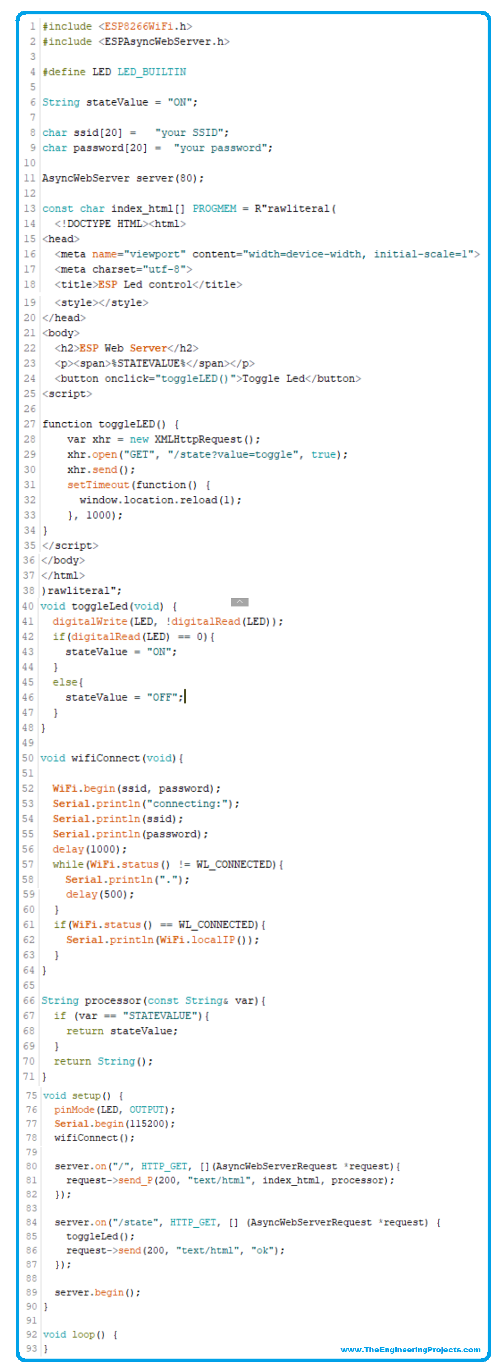
- In our browser:
Conclusion
In this project, we saw a very simple application of the power that the ESP8266 WiFi has. In the HTML file, page styling could also be included to make the page prettier.
And with that base, it's possible to expand into several cool projects. A temperature monitor via Wifi? Security systems? Home automation systems? These are just a few examples. The limit is up to your creativity.


