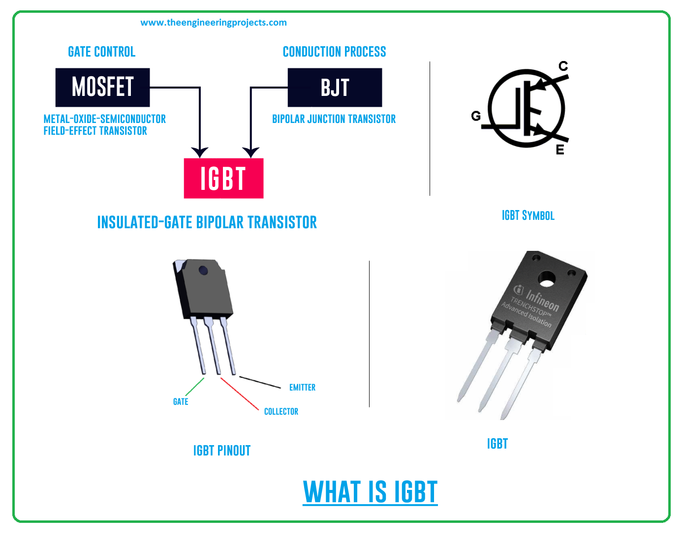
Hi Guys! Hope you’re well. In this post today, we’ll cover What is IGBT? We’ll also discuss IGBT Full Form, Pinout, Meaning, Symbol & Working.
BJT (bipolar junction transistor) and MOSFETs (metal-oxide-semiconductor field-effect transistor) are commonly used electronic switches that we’ve already studied in detail. These devices are useful when you deal with low-current applications, however, when it comes to high-current applications, these devices don’t work as expected. This is where the IGBT transistor comes in handy. This device is a combination of both BJT and MOSFET and stands fit for high-current applications. In this post, we’ll cover What is IGBT in detail. Let’s get started:
1. What is IGBT?
IGBT is a three-pin device made of semiconductor material and is used for fast-switching applications. It comes with input characteristics of the MOSFETs and output characteristics of the BJT.
IGBT Full Form
IGBT stands for Insulated Gate Bipolar Transistor.IGBT Symbol
The following figure shows the IGBT symbol.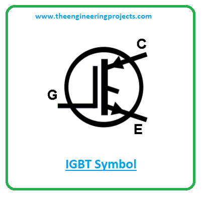
IGBT Pinout
The following figure shows the IGBT Pinout.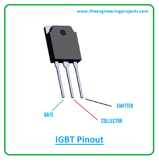
IGBT Meaning
The Insulated Gate Bipolar Transistor comes with the insulated gate from the MOSFET at the input with the conventional bipolar transistor at the output. The emitter and collector terminals are the conduction pins of the IGBT. While the gate terminal at the input is the control terminal. The conduction is controlled by the gate terminal.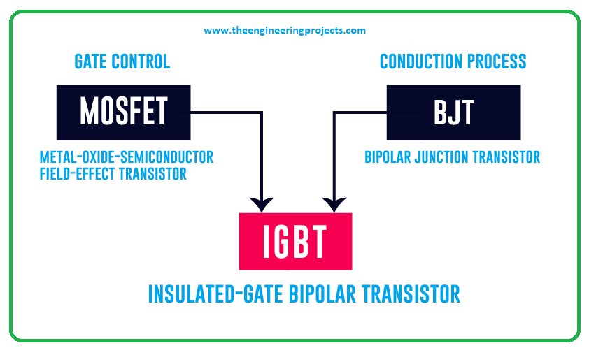
2. IGBT Working
- Like MOSFETs, IGBT is a voltage-controlled device which means the only small voltage is required at the gate terminal to initiate the conduction process. IGBT can switch current from collector to emitter terminal which means it can switch in the forward direction only.
- The following figure shows the IGBT switching circuit. In this case, a small voltage is applied at the gate terminal which results in the switching of the motor from a positive supply. The resistor is included to control the current passing through the motor.
- The graph below shows the IGBT input characteristics. It is a graph between the voltage applied at the gate terminal vs current passing through the collector terminal.
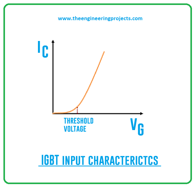
- No current will flow through the IGBT when there is no voltage applied at the gate pin. In this case, the transistor will remain turned off. However, when voltage is applied at the gate terminal, the current will remain zero for a little while. When the voltage exceeds the threshold voltage, the device will start conducting and current will flow from collector to emitter terminal.
- The graph below shows the IGBT output characteristics. This is a graph between the voltage at the collector and emitter terminals vs current passing through the collector terminal.
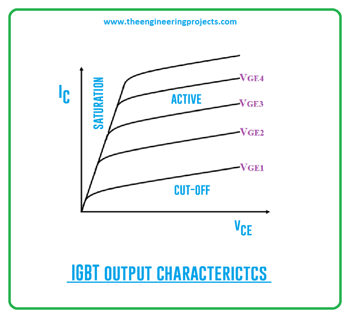
- This graph contains three stages. The first one is the cut-off region when there is no voltage applied at the gate terminal. At this stage, the transistor will remain turned off and there will be no current flowing through the transistor.
- When the voltage at the gate terminal increases, and if it stays below the threshold voltage, it will result in the small leakage current flowing through the device but the device will remain in the cut off region.
- However, when the applied voltage at the gate terminal exceeds the threshold voltage the device will move to the active region and in this case, a significant current will flow from collector to emitter terminal.
- At this stage, applied voltage and resulting current will be directly proportional to each other. More voltage will result in more current flow at the collector terminal.
3. IGBT Modules
IGBT is used in a range of electronic switching applications where both BJT and MOSFET fail to deliver the desired results in high current applications. This hybrid combination of two transistors features voltage-controlled characteristics like MOSFETs and conduction and switching characteristics like BJT. The IGBT devices are divided into two main types.- Non-Punch Through IGBT [NPT-IGBT]
- Punch Through [PT-IGBT]
1. Non-Punch Through IGBT [NPT-IGBT]
- These IGBTs are also called symmetrical devices. The IGBT transistors that come with an n+ buffer layer are called Punch Through-IGBT (PT-IGBT)
- They are called symmetrical devices because both reverse and forward breakdown voltages are the same in this case. They are more thermally stable and more rugged in short-circuit failure mode.
- Moreover, the changing temperature won’t have a significant effect on turn-off loss i.e. it remains unchanged with temperature. And the P-layer (collector side) is highly doped in Non-Punch Through IGBT.
- They are developed with less expensive diffusion process technology, making them ideal choices for AC circuits. Plus, the structure of NPT ensures the bidirectional blocking capability in these devices. The N base is thick in this case.
2. Punch Through [PT-IGBT]
- These IGBTs are also called asymmetrical devices. They are called asymmetrical because here forward breakdown voltage is more than the reverse breakdown voltage.
- These devices are less thermally stable and less rugged in short-circuit failure mode. And in this case, turn-off loss is directly proportional to temperature, it increases significantly with the increase in temperature.
- These IGBTs are manufactured using an expensive N-epitaxial water process. They contain a thin N base and the PT structure comes with lower reverse blocking capability.
- They are widely used in DC circuits where the voltage support in the reverse direction is not needed by the device.
4. IGBT vs MOSFET
- Both IGBT and MOSFETs are transistors and voltage-controlled devices but they are different in terms of composition and performance.
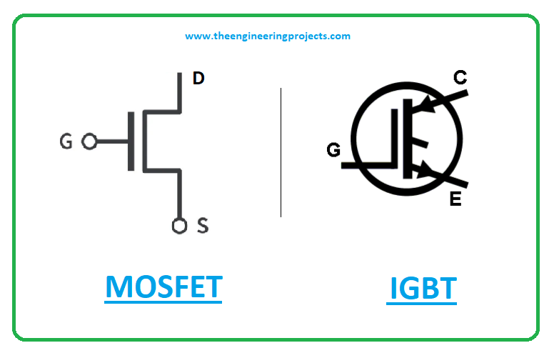
- IGBT is composed of collector, emitter, and gate pins, whereas MOSFET, on the other hand, is made of the drain, source, and gate terminals. IGBT is better than MOSFETs in terms of performance.
- IGBT needs an extra freewheeling diode to drive the current in a reverse direction. The inclusion of this freewheeling diode makes this device the best pick for high voltage applications.
- IGBT is preferred for high voltage (more than 1000V), low frequency (Less than 20 kHz), small or narrow load or line variations; high operating temperature; low duty cycle, and, more than 5kw output power rating applications.
- MOSFET, on the other hand, is preferred for large duty cycles, wide load or line variations, high frequency (more than 200KHz), and low voltage (Less than 250V) applications.
- After the MOSFET, the IGBT is widely employed in electronic devices. The IGBT covers 27% of the power transistor market.
- The greater power gain and lower input losses of IGBT make this device preferable over both MOSFETs and BJT. You’ll find high-voltage and high-current bipolar transistors in the market, but they come with one drawback.
- Their switching speed is not so good, they take time to switch the devices. Similarly, MOSFETs alone have high switching speeds, no doubt. But high-current and high-voltage MOSFET components are too expensive compared to IGBT.
5. IGBT Inverter
The IGBT transistors are employed in VFD (variable frequency drive) inverter modules as the high power electronic switch due to the following reasons.- It carries a high current-carrying capacity. Some IGBT devices come with a maximum rated collector current Ic (max) of around 100A. And if this fails to meet the requirement, two or more IGBTs can be combined to meet the purpose.
- IGBTs come with the open circuit rated collector voltage up to 1.6kV. This explains there are devices preferable for functions off rectified three and single phase mains… ranging from 110Vac to 690Vac.
- An IGBT contains a high impedance gate terminal which projects it is technically simple to control the device by controlling the gate terminal.
- The low conduction losses of the IGBT ensure a low on-state voltage.
- Recall, the IGBT carries a fast switching speed. This means you can achieve high switching frequencies with reduced switching losses that play a key role in motor noise and harmonic reduction.
- The IGBT carries a wide Reverse Bias Safe Operating Area (RBSOA) that explains it is comparatively secured against load short circuits.
6. IGBT Applications
The combination of high switching speed like MOSFETs and low conduction loss like BJT will result in developing the optimal solid-state of IGBT, making it a suitable pick for a range of applications. The following are the IGBT applications.- Used in AC and DC motor drives
- Employed in Unregulated Power Supply (UPS)
- Used in Switch Mode Power Supplies (SMPS)
- Used in electric cars and plasma physics
- Employed in traction motor control and induction heating
- Incorporated in inverters, converters, and power supplies
That’s all for today. Hope you find this article helpful. If you have any questions, you can pop your comment in the section below. I’m happy and willing to assist you the best way I can. Feel free to share your valuable suggestions and feedback around the content we share so we keep coming back with quality content tailored to your needs and requirements. Thank you for reading the article.


