Hi Everyone! Hope you’re well today. Happy to see you around. In this post today, I’ll walk you through the Introduction to TDA2005.
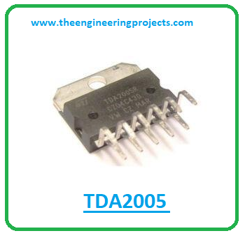
TDA2005 is a 20-watt Class B dual audio amplifier integrated chip. It comes in a Multiwatt11 package and is carefully designed for car radio applications. It can support the current up to 3.5A which is quite high which makes it a suitable pick for constructing power booster amplifiers.
I suggest you read this post all the way through as I’ll detail the complete Introduction to TDA2005 covering datasheet, pinout, features, and applications. Let’s jump right in.
Introduction to TDA2005
- TDA2005 is a 20-watt Class B dual audio amplifier integrated chip. It is particularly designed for car radio applications.
- It comes with a high current capability and features a total of 11 pins on board.
- It supports low impedance loads of around 1.6 with an output power of more than 20 W.
- TDA2005 features a bridge or stereo setup and the total power dissipation is 30W.
- This device is mainly employed in applications where high-output audio power amplification is required.

- Incorporated with protection against load dump voltage surge, this device features a maximum supply voltage of around +28V.
- The repetitive current through each output is 3.5A while the maximum non-repetitive peak current through each output is 4.5A.
- The storage temperature range is -40°C to 150°C while the operating temperature range is -23°C to 130°C.
- This chip employed in stereo amplification applications will exhibit a voltage gain of 51 dB.
TDA2005 Datasheet
Before you apply this device to your electrical project, it’s wise to go through the datasheet of the component that features the main characteristics of the device. You can download the datasheet of TDA2005 by clicking the link mentioned below.TDA2005 Pinout
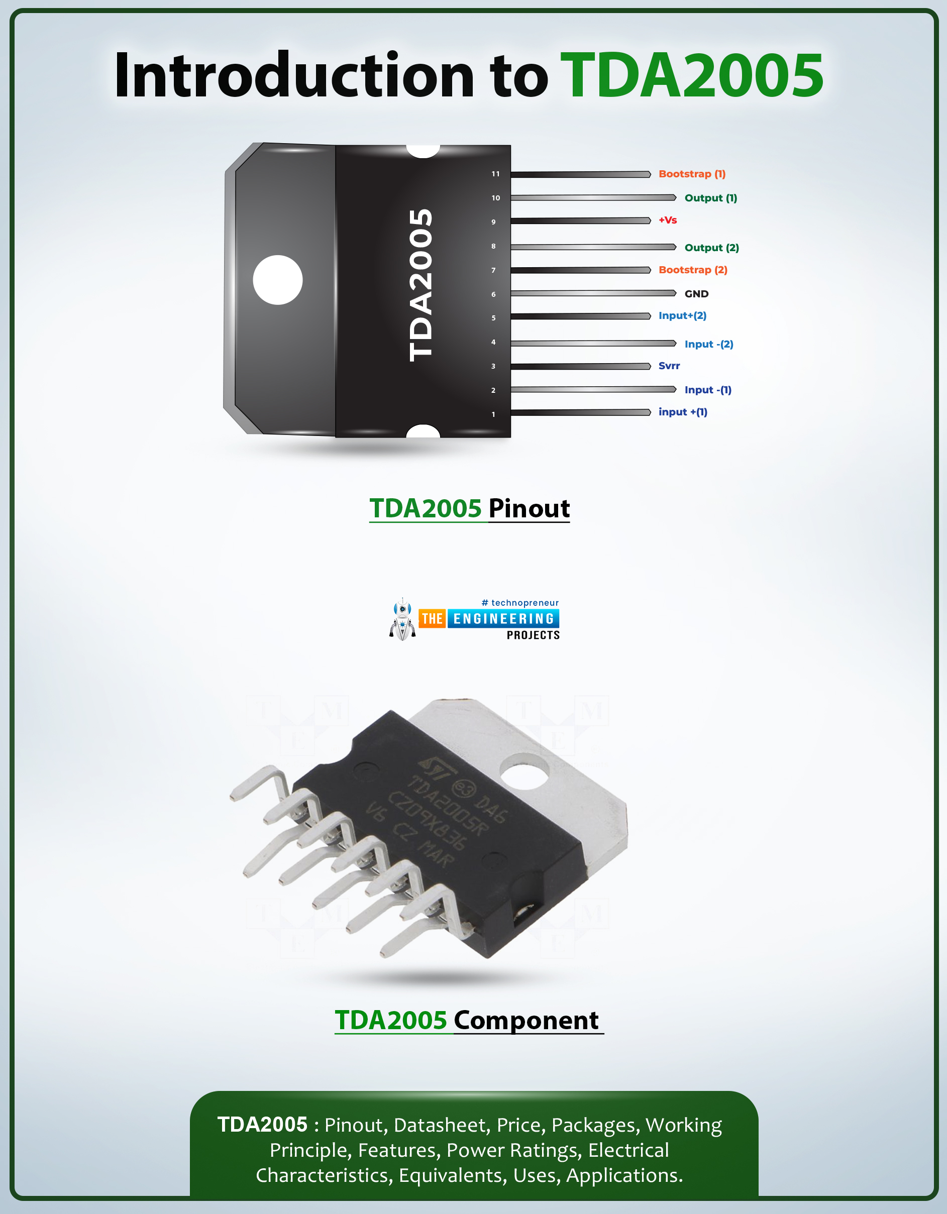
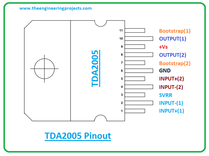
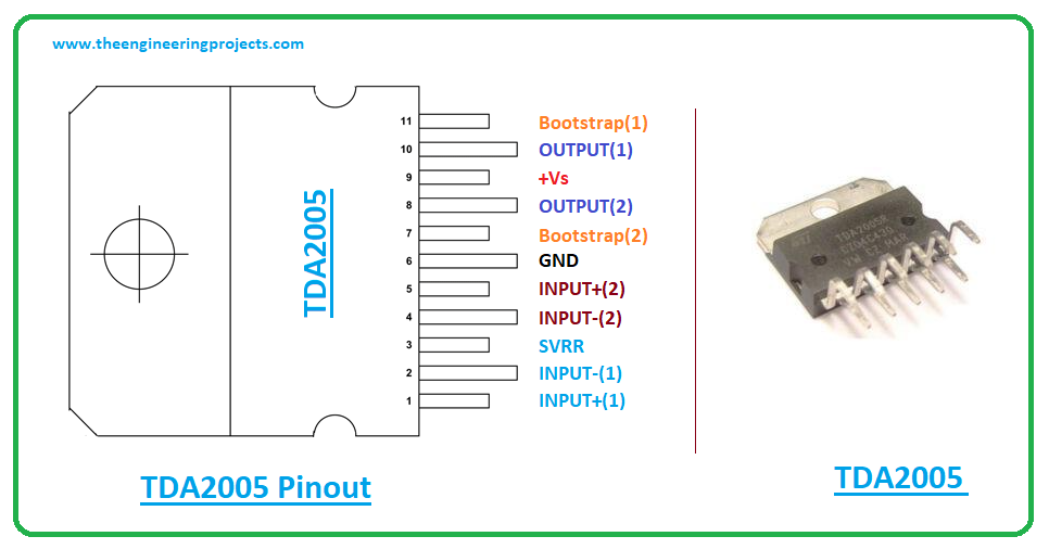
The TDA2005 is an 11-pin device. The following figure represents the pinout diagram of TDA2005.
| Pin Description of TDA2005 | ||||
|---|---|---|---|---|
| Pin No. | Pin Description | Pin Name | ||
| 1 | Non-Inverting Input of amplifier 1 | INPUT+(1) | ||
| 2 | Inverting Input of amplifier 1 | INPUT-(1) | ||
| 3 | Supply Voltage Rejection Ratio | SVRR | ||
| 4 | Inverting Input of amplifier 2 | INPUT-(2) | ||
| 5 | Non-Inverting Input of amplifier 2 | INPUT+(2) | ||
| 6 | The ground is connected to this pin | GND | ||
| 7 | Amplifier 2 bootstrap capacitor | BOOTSTRAP(2) | ||
| 8 | The output of amplifier 2 | OUTPUT(2) | ||
| 9 | Positive Power Supply | +VS | ||
| 10 | The output of amplifier 1 | OUTPUT(1) | ||
| 11 | Amplifier 1 bootstrap capacitor | BOOTSTRAP(1) | ||
TDA2005 Features
- Overheat protection and output short circuit protection
- A few components required to put the amplifier in working condition
- Operating voltage range = +8 to +18V
- High output power - Po=10 + 10 W @ RL = 2 ?, Po = 20 W @ RL = 4 ?
- Programmable gain and bandwidth
- Peak supply voltage = +40V for 50ms
- Loudspeaker protection against short circuit
- Incorporated with protection against load dump voltage surge
- Supply voltage Max. = +28V
- Comes with protection against fortuitous open ground
- Total power dissipation = 30W
- Comes with Bridge or Stereo setup
- Repetitive current through each output = 3.5A
- The non-repetitive peak current through each output Max. = 4.5A
- Storage temperature range = -40°C to 150°C
- Operating temperature range = -23°C to 130°C
TDA2005 Applications
The TDA2005 is used in the following applications.- Employed in Car radio
- Used in Microphone amplifiers
- Used in audio power amplifiers
- Incorporated in Woofer amplifiers
- Used in Music players
That’s all for today. Hope you found this article helpful. If you have any questions, you can pop your comment in the section below. I’d love to help you the best way I can. Feel free to share your valuable suggestions around the content we share so we keep creating quality content customized to your exact needs and requirements. Thank you for reading the article.


Dekuji mnohokrat! Budte zdravi. Reply