Bonjour trainees!!! Welcome to the Engineering projects, We hope you are doing great. In our previous lecture, we discussed the first type of clippers in detail i.e. Series Clippers. Today, we are going to discuss the next two types of Clippers i.e. Shunt Clippers and Dual Clippers. Here are the types of Clippers from the last lecture:
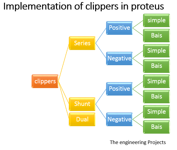
So, today, we are going to cover the below concepts:
- what is a Shunt Clipper?
- Types of Shunt Clippers
- Implementation of shunt Clippers in Proteus ISIS.
- Dual Clippers basics.
- Implementation of Dual Clippers in Proteus ISIS.
So, let's get started:
What is a Shunt Clipper?
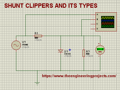
- In Shunt Clippers(Parallel Clippers), the diode is connected in Shunt(Parallel) to the input signal source & the load resistance, as shown in the below figure:
As the diode is in parallel with the load & source, so during the positive half cycle, the diode will be in the forward-biased state(short circuit) and thus no current will flow to the load resistance. While during the negative half cycle, the diode will be in a reverse-biased state(open circuit) and the load resistance will get all the current flow.
Now, let's have a look at the types of Shunt Clipper:
Types of Shunt Clippers
Shunt clippers are Classified into four main types, named:
- Positive
- Positive with bias
- Negative
- Negative with bias
Let's implement these Clipper types in the Proteus:
Implementation of Shunt Clippers in Proteus
So, open your Proteus software and add these components:
Components Required
- Vsine
- Diode
- Resistor
- Ground terminal
- Oscilloscope
- We can get the first three components from the "Pick library" by searching for the required component.
- We can get the Ground Terminal by left-clicking on the screen and then go to Place>Terminal>Ground.
- Get the Oscilloscope from the "Virtual Instrument" in the leftmost bar.
Now let's design the first type of Shunt Clipper:
Positive Shunt Clipper:
Now place the above components in the Proteus workspace and design the circuit, as shown in the below figure:
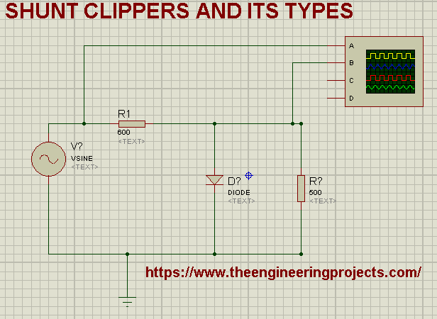
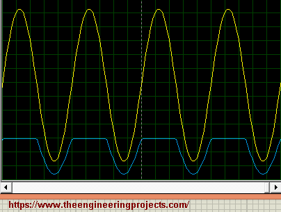
As you can see in the above figure, the diode is placed parallel to the load resistance. The arrowhead of the diode points opposite to the input source. As we discussed above, the load resistance will get voltage only if the diode is in a reverse-biased state. In the current arrangement, during the negative cycle of the AC signal, the diode will be reverse-biased, and the load will get complete power. The positive cycle of the input will be clipped off, as the diode will be in a forward-biased state, not allowing any current to flow through the load.
Change the values of components according to the below table:
| Components | Value |
| Resistor R1 | 600 ohm |
| Resistor R2 | 500 ohm |
| Vsine | Amplitude =110V,Frequency= 1000Hz |
| Oscilloscope | Time= 0.2m-1,Voltage 20V |
- Now run the simulation and you will definitely acquire the required output:
Positive with bias:
If you recall from our previous lecture on Series Clippers, we have added a battery in the bias clippers. Here, we are going to do the same, as shown in the below figure:
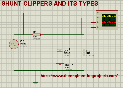
As we can see in the above figure, a battery of 5V is added in series with the diode. By adding the battery in the circuit of positive shunt clippers, we can easily control the amount of signal to be clipped. This arrangement is called Positive Shunt Clippers with bias or Biased Positive Shunt Clippers.
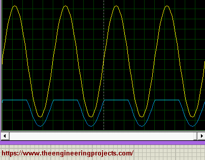
In the above circuit, we placed the battery just after the diode and the Positive Terminal of the battery connects with the diode's arrowhead and the negative terminal is connected to the Vsine source.Here's the output of Positive Bias Shunt Clipper:
Negative Shunt Clippers:
In negative Shunt Clippers, the diode polarity is reversed i.e.the positive end of the diode is connected to the negative terminal of the battery and the negative end of the diode is connected to the positive terminal of the battery, as shown in the below figure:
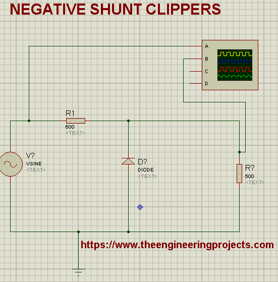
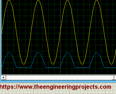
In this arrangement, the diode is forward-biased during the negative half cycle, so no current will pass to the load. We can say, the negative cycle is clipped off. While in the positive cycle, the diode is reversed bias(open circuit) and thus current is flowing through the load resistor.
We will get the following waveform on the oscilloscope:
Biased Negative Shunt Clippers:
By now, you must have understood that an extra battery is added in series with the diode to create a Bias Clipper. As it's a negative bias, so the polarity of the battery is reversed i.e. the negative terminal of the battery is connected to the diode and the positive terminal of the battery is connected to the Vsine Source. The output is shown in the below figure:

So, that was all about the Shunt Clippers. Now let's have a look at the third tye of clippers i.e. Dual Clippers. Let's get started:
What is a Dual Clipper?
As the name depicts, the Dual Clipper is a combination of two types of Shunt Clippers i.e.
- Biased Shunt Positive Clipper.
- Biased Shunt Negative Clipper.
Now, let's move towards its simulation:
Dual Clipper Proteus Simulation
We have studied both Positive & Negative Bias Shunt Clippers in the previous section, so now we need to add both clippers in a single circuit, as shown in the below figure:

As you can see in the above figure, the circuit has four parallel branches, let's discuss them one by one:
- The First branch has an AC input source.
- The second branch has a Biased Shunt Positive Clipper i.e. Diode and a battery.
- The third branch has a Biased Shunt Negative Clipper i.e. Diode and a battery, but here the polarity is reversed.
- In the fourth branch, we have the load.
- Pop the Play button, and have a look at the output:
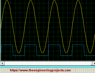
One can see that we got a square wave that conducts the current in both directions but in clipped form. We need Dual clippers in the place where we need to clip some part of both sides of the sinusoidal wave.
So, that's all for today. In this article, we discussed what are Shunt Clippers? what are their types? and How to simulate in Proteus? We also discussed Dual Clippers along with their implementation in Proteus ISIS. Take care!!!


