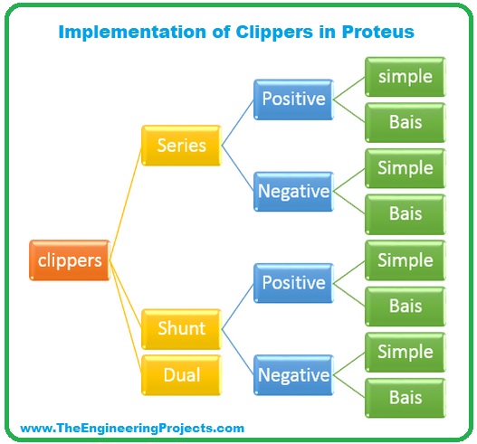
Hello friends, I hope you all are having fun. In today's tutorial, we will have a look at Series Clippers & their types in detail, we will also implement the simulations of Series Clippers in Proteus software. In the next article, we will discuss the next two types of Clippers i.e. Shunt Clippers & Dual Clippers. Today, We are going to learn:
- What is a Clipper?
- What are the types of Clippers?
- Series Clippers Simulations in Proteus.
What is a Clipper???
- Clipper (also known as Limiter) is an electronic circuit, which clips or limits the amplitude(positive, negative or both) of an AC source wave.
- Diodes are normally used for designing Clippers and such circuits are normally referred as Diode Clipping Circuits (Diode Limiting Circuits).
- Here's an example of a Diode Clipping Circuit, where we are clipping the positive amplitude of the AC pulse:
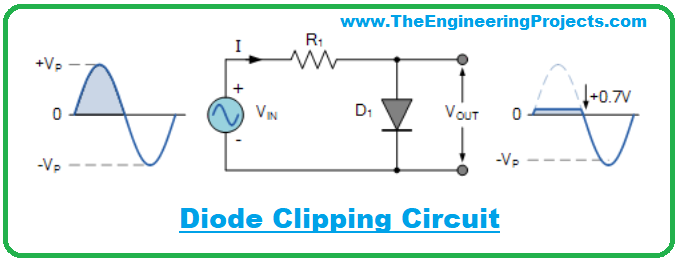
- As you can see in the above figure, we are clipping the positive side but if we want to clip the negative side, we just need to reverse the diode polarity.
- Clippers are normally used for protection purposes i.e. if there are some voltage spikes then clip it to secure home appliances.
- Half wave Rectifier is also a type of clipper as it clips one side of the AC pulse to 0V.
Now, let's have a look at different types of clippers:
Types of Clippers

In the previous section, we have had a complete understanding of what is clipper. Now let's have a look at three different types of Clippers:
- Series Clippers.
- Positive.
- Positive with bias.
- Negative.
- Negative with bias.
- Shunt Clippers.
- Positive.
- Positive with bias.
- Negative.
- Negative with bias.
- Dual (Combination) Clippers.
Series Clippers Simulation in Proteus
- First of all, we need to open the Proteus ISIS software to design our circuit.
- Select the following components from the "Pick Components" section:
- Diode
- Resistor
- Vsine source
- Battery
- So, first of all, let's place our AC source Vsine and GND in the proteus workspace.
- Double-click on the Vsine source and change the value of amplitude and frequency to 11V and 1000Hz respectively.
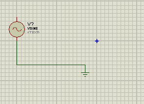
Our power source is ready, now let's design different types of Series Clippers in proteus:
1. Positive Series Clippers in Proteus ISIS
- In Positive Series Clipper, the positive half cycle of the wave is clipped(removed).
- In the positive clipper circuit, the arrowhead of the diode points towards the input source.
- So, let's design the circuit as shown in the below figure:
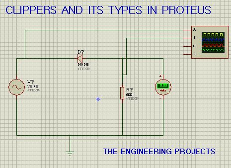
- As we can see in the above figure, diode D is connected in series with the load
resistor and is pointing towards the AC source.
- Double-click at the resistor and change its value from 10k ohm to 500 ohms.
- We'll also add the DC voltmeter to show the difference between biased and unbiased circuit
- We've connected terminal A of the oscilloscope with the AC Source(Vsine) and terminal B is placed after the diode.
- This is the time to pop the play button and set values of the oscilloscope according to the below table:
| Components | Values |
| Channel A | 20V |
| Channel B | 20V |
| Time | 0.2ms-1 |
- If everything goes fine, we will get the required output as shown in the figure:
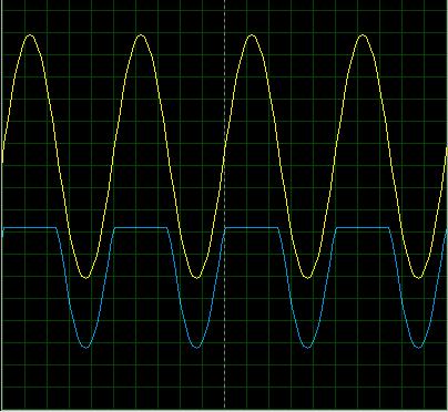
- In the above figure, the Yellow curve is showing the input voltage, while the blue line is the output voltage(after the diode) received by the load resistor.
- We can clearly see that the positive side of the AC source waveform is now clipped and that's why it's called Positive Series Clipper.
2. Positive with Negative Bias Series Clipper
The Positive Series Clipper removes the positive side of the curve completely but what if we want to clip only 25% of the positive side? In that case, we use positive with Negative Bias Series Clipper. It's circuit is shown in the below figure:
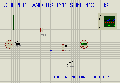
As we can see in the above figure, we have added an extra element called Battery.The rest of the circuit is same as that of the Positive Series Clipper i.e. the diode is pointing towards the current source and is in series with the resistor.
The volt meter is giving us -5V, where the 5V is coming from the added battery and the negative sign shows that the circuit is negative bias.
- The output for the circuit on the oscilloscope is shown below:
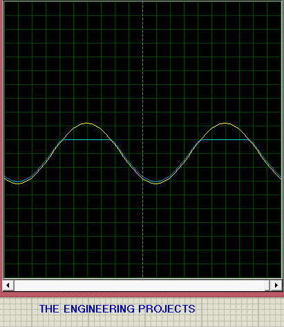
As you can see in the above figure, the output curve is slightly clipped at the top. If we reduce the battery voltage, the clipping of the curve increase and at 0V the complete positive part will be clipped out(same as Positive Series Clipper).
If you want a clipper with a positive bias, simply change the direction of the battery. Connect the negative terminal of the battery with the negative side of the diode. It's a task, post your results in the comments.
3. Negative Series Clipper in Proteus
- In a Negative Series Clipper, the negative half cycle of the wave is clipped(removed).
- In negative clipper circuits, the arrowhead of the diode points towards the load resistor.
- Here's the circuit diagram of the Negative Series Clipper:
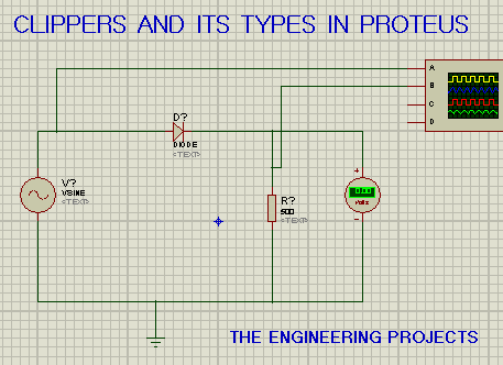
- The circuit is the same as that of the Positive Series Clipper with a slight difference in the direction of the diode.
- The output of the oscilloscope for the series circuit of negative clippers shows us that the negative side of the wave is clipped:
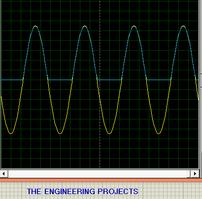
4. Negative with negative bias Series Clippers
As we discussed, the whole negative part of the signal gets clipped in the Negative Series Clipper. So, in order to clip a certain amount of negative side, we need to add a new battery source and this model is called Negative with Negative Bias Series Clipper. It's circuit diagram is shown in the below figure:
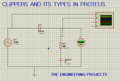
As we can see in the above figure, the diode is pointing towards the load resistor. We have connected the negative terminal of the battery with the positive side of the diode. Here are the results from the oscilloscope:
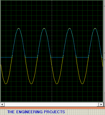
So, that was all for today. In this article, we studied the series clipper and its types, along with their simulations in Proteus software. I hope you have enjoyed today's lecture. Let me know your feedback/queries in the comments. Have fun!!!


